
 My Inquiry
 My Account


Skyworks Solutions Inc. SI5338N-B05554-GMR
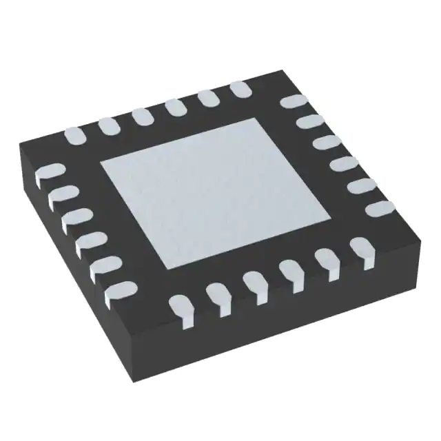
- Part No.:
- SI5338N-B05554-GMR
- Manufacturer:
- Skyworks Solutions Inc.
- Category:
- Application Specific Clock/Timing
- Package:
- 24-VFQFN Exposed Pad
- Datasheet:
-
 SI5338N-B05554-GMR.pdf
- Description:
- I2C CONTROL, 4-OUTPUT, ANY FREQU
- Quantity:
- Payment:

- Shipping:

Inventory:1,796
Please send an inquiry. Send us your inquiry, and we will respond immediately.
Product details
Overview
SI5338N-B05554-GMR from Skyworks Solutions is an I²C-programmable quad clock generator with four independently configurable differential or single-ended outputs, 0.7 ps RMS typical phase jitter, PCIe Gen 1–4 Common Clock and Gen 3 SRNS compliance, and operation across –40 to +85 °C in a 4 × 4 mm 24-QFN package. It replaces up to four crystal oscillators in Ethernet switch/router and FPGA clocking systems.
For engineers reviewing the SI5338N-B05554-GMR datasheet, SI5338N-B05554-GMR pinout, SI5338N-B05554-GMR application, or SI5338N-B05554-GMR equivalent, key selection criteria include its MultiSynth™-based any-frequency synthesis (0.16–710 MHz per output), independent output voltage support (1.5/1.8/2.5/3.3 V), spread-spectrum capability (0.5–5.0% down-spread), and I²C/SMBus programmability with ClockBuilder Pro software integration.
Technical Context
The SI5338N-B05554-GMR implements a two-stage PLL architecture: a high-performance integer-N PLL (Stage 1) locks to one of six input references (crystal, CMOS, SSTL/HSTL, or differential), followed by four independent MultiSynth™ fractional-N synthesis blocks (Stage 2) generating each output. Each MultiSynth supports frequency resolution down to 1 ppb and programmable phase offset (±45 ns) in <20 ps steps.
Its output stage provides per-driver configurability for LVPECL/LVDS/HCSL/CMOS/SSTL/HSTL formats, with independent VDDO supplies enabling mixed-voltage operation. The device supports external feedback for zero-delay mode, loss-of-lock and loss-of-signal alarms, and glitchless frequency adjustment via 1 ppm increment/decrement control.
Key Specifications
| Parameter | Value and Actual Design Meaning |
|---|---|
| Phase Jitter (RMS) | 0.7 ps - meets PCIe Gen 3 SRNS and GbE jitter requirements at 125 MHz output |
| Output Frequency Range | 0.16–710 MHz - covers PCIe 100 MHz, Ethernet 125/156.25 MHz, Fibre Channel 1.0625 GHz (via Fvco/4), and processor clocks |
| Input Reference Support | 8–30 MHz crystal, 5–200 MHz CMOS, 5–350 MHz SSTL/HSTL, 5–710 MHz differential - enables flexible system clock sourcing |
| Supply Voltages | VDD = 1.8/2.5/3.3 V; VDDOx = 1.4–3.63 V - allows mixed-signal domain interfacing without level shifters |
| Operating Temperature | –40 to +85 °C - qualified for industrial and telecom line card environments |
| Package | 24-pin QFN, 4 × 4 mm - space-constrained PCBs in 1U servers and embedded networking gear |
| Core Current (Typ) | 45 mA at 100 MHz on all outputs - enables low-power timing in fanless edge devices |
Pinout & Package
SI5338N-B05554-GMR is housed in a 24-lead, 4 × 4 mm QFN package with exposed thermal pad. Pin assignments follow the standard Si5338 top-view layout: IN1/IN2 (differential ref 1), IN3/IN4 (single-ended ref 2), IN5/IN6 (differential ref 3), CLK0A/CLK0B through CLK3A/CLK3B (four differential output pairs), VDDO0–VDDO3 (independent output supply pins), VDD (core supply), SCL/SDA (I²C interface), INTR (interrupt output), and RSVD_GND (reserved ground).
| Pin/Terminal | Circuit Role | Design Meaning |
|---|---|---|
| CLK0A / CLK0B | Differential Output Pair 0 | LVPECL/LVDS/HCSL-configurable clock output with independent VDDO0 supply and phase/frequency control |
| CLK1A / CLK1B | Differential Output Pair 1 | Independent synthesis path; supports same format/voltage as CLK0 but with separate MultiSynth divider settings |
| CLK2A / CLK2B | Differential Output Pair 2 | Capable of >350 MHz (Fvco/4 or Fvco/6) when other outputs are below 350 MHz - enables high-speed SerDes clocking |
| CLK3A / CLK3B | Differential Output Pair 3 | Full feature parity: spread spectrum, phase adjust, frequency increment/decrement, and loss-of-signal monitoring |
| SCL / SDA | I²C Serial Interface | Standard 100/400 kHz SMBus-compatible bus for configuration, status readback, and runtime reprogramming |
| INTR | Interrupt Output | Open-drain signal asserting on loss-of-lock, loss-of-signal, or register-access error - enables system-level fault detection |
| VDDO0–VDDO3 | Output Buffer Supplies | Each powers its associated output driver pair; allows simultaneous LVDS (2.5 V) and HCSL (1.8 V) outputs on same device |
| IN1/IN2, IN5/IN6 | Differential Input Pairs | Accept 5–710 MHz AC-coupled signals with internal 10 kΩ termination - eliminates external bias networks |
| IN3/IN4 | Single-Ended Inputs | Support 5–200 MHz CMOS-level clocks; VIH/VIL thresholds scale with VDD - simplifies connection to FPGA GPIO |
Key Features
| Feature | Design Value |
|---|---|
| MultiSynth™ Any-Frequency Synthesis | Four independent output clocks synthesized from single reference with true zero-ppm accuracy and 1 ppb resolution |
| PCIe Gen 1–4 Compliance | Meets Common Clock jitter specs (0.11–0.45 ps RMS) and Gen 3 SRNS requirements - validated per Intel Clock Jitter Tool v1.6.4 |
| Independent Output Voltage Control | VDDOx pins enable concurrent LVDS (2.5 V), HCSL (1.8 V), and CMOS (3.3 V) outputs without external regulators |
| Glitchless Frequency Adjustment | 1 ppm step size with <667 ns update time via PIN or I²C - enables dynamic rate adaptation in packet-switched systems |
| Programmable Spread Spectrum | Configurable 0.5–5.0% down-spread at 33–63 kHz modulation rate on any output - reduces EMI peak emissions by >10 dB |
| External Feedback Zero-Delay Mode | Supports synchronous clock distribution where output phase aligns precisely with input reference - critical for deterministic latency in telecom |
Applications
| Ethernet Switch/Routing Timing | PCIe Gen 1–4 Clocking |
|---|---|
Use Scenario: 10 GbE line cards requiring synchronized 156.25 MHz and 125 MHz clocks for MAC/PHY and SerDes interfaces. IC Role / Device Role / Timing Role: Quad clock generator providing four low-jitter outputs: two 156.25 MHz LVDS clocks for PHYs, one 125 MHz HCSL for CPU interconnect, and one 100 MHz CMOS for management controller. Use Value: Eliminates four discrete oscillators while maintaining sub-1 ps RMS jitter across all outputs - reduces BOM cost and board area by 65% versus discrete solution. | Use Scenario: Server motherboard with dual x16 PCIe Gen 4 slots, SATA controller, and BMC requiring compliant common-clock sources. IC Role / Device Role / Timing Role: Generates 100 MHz PCIe Common Clock (HCSL), 100 MHz SATA Refclk (LVDS), 25 MHz BMC clock (CMOS), and 100 MHz secondary PCIe clock (LVDS) - all from single 25 MHz crystal. Use Value: Meets PCIe Gen 4 Common Clock RMS jitter spec (≤0.45 ps) and supports SRNS mode for Gen 3 endpoints - enables full backward compatibility without redesign. |
| Broadcast Video/Audio Sync | FPGA & Processor Clocking |
Use Scenario: SMPTE 2110 IP video router needing precise 27 MHz, 74.25 MHz, and 148.5 MHz clocks for SDI-to-IP conversion and frame synchronization. IC Role / Device Role / Timing Role: Synthesizes three exact frequencies simultaneously: 27 MHz (SMPTE ST 259), 74.25 MHz (HD-SDI), and 148.5 MHz (3G-SDI), plus spare 100 MHz for control logic. Use Value: Achieves 0 ppm frequency accuracy on all outputs using MultiSynth™ - eliminates timing drift between video/audio streams and ensures lip-sync compliance. | Use Scenario: Xilinx Kintex Ultrascale+ FPGA-based test equipment requiring multiple domain clocks: 300 MHz transceiver refclk, 100 MHz AXI interface, 50 MHz ADC sampling, and 25 MHz debug UART. IC Role / Device Role / Timing Role: Provides four independent, phase-aligned clocks with programmable skew (±45 ns in <20 ps steps) to synchronize high-speed I/O and processing pipelines. Use Value: Enables deterministic setup/hold timing across FPGA domains - reduces timing closure effort by eliminating external delay lines and manual PCB trace tuning. |
Equivalent & Alternatives
The following parts are listed as comparable options for similar quad clock generator applications.
| Alternative Part | Technical Difference | Application Difference | Selection Advice |
|---|---|---|---|
| Si5338A-B05554-GM | Same silicon die and pinout; factory-programmed with pre-defined configuration stored in OTP NVM - no I²C programming required at power-up | Fixed-frequency use cases only; lacks runtime reconfiguration capability of SI5338N-B05554-GMR | Select when production volume justifies OTP customization and field updates are unnecessary |
| LMK04832ISQE/NOPB | Two-stage jitter cleaner with integrated LDOs; higher power (120 mA typ); supports JESD204B subclass 1 deterministic latency | Requires external 100 MHz VCXO for optimal jitter cleaning; not suitable for direct crystal drive or PCIe common clock | Select when ultra-low additive jitter (<0.1 ps RMS) and deterministic latency are mandatory, and power budget permits |
Compared with Si5338A-B05554-GM, SI5338N-B05554-GMR offers full I²C programmability for prototyping and multi-config systems; compared with LMK04832ISQE/NOPB, it delivers lower power and direct crystal support but lacks jitter cleaning and deterministic latency features.
Availability
SI5338N-B05554-GMR is available at Aetrix Electronics and suitable for Ethernet switch/router, PCIe Gen 1–4 server boards, broadcast video routers, and FPGA-based test equipment requiring stable component supply across extended product lifecycles.
Supply support for SI5338N-B05554-GMR includes scheduled delivery planning, volume procurement assistance, BOM continuity management, traceable sourcing, and lifecycle availability coordination for OEM customers, industrial embedded developers, connected-device designers, and electronics production programs.
Manufacturer
Skyworks Solutions is a global semiconductor company specializing in analog and mixed-signal connectivity solutions for infrastructure, automotive, and mobile markets.
The Si5338 product line was designed to replace multiple discrete oscillators with a single programmable clock generator for high-speed digital systems - targeting PCIe, Ethernet, broadcast, and FPGA applications demanding low jitter and flexible frequency synthesis.
FAQ
What is the primary function of the SI5338N-B05554-GMR in a timing architecture?
The SI5338N-B05554-GMR serves as an I²C-programmable quad clock generator that synthesizes four independent, low-jitter output clocks from a single reference source. Its core function is to replace up to four discrete crystal oscillators while delivering 0.7 ps RMS phase jitter, PCIe Gen 1–4 compliance, and support for mixed-signal voltage domains - making SI5338N-B05554-GMR ideal for space-constrained, high-performance timing applications in networking and computing hardware.
Does the SI5338N-B05554-GMR support direct connection to a crystal oscillator?
Yes, the SI5338N-B05554-GMR supports direct connection to an 8–30 MHz fundamental-mode crystal via its IN1/IN2 pins. The device integrates on-chip load capacitance (11–13 pF supported, 17–19 pF recommended) and automatic crystal drive-level control (max 100 µW), eliminating external capacitors and enabling robust start-up across temperature. This capability is confirmed in Tables 8–11 of the official Skyworks datasheet Rev. 1.6 for SI5338N-B05554-GMR.
Can the SI5338N-B05554-GMR generate frequencies above 350 MHz on multiple outputs simultaneously?
No. Per Table 6 and Section 3.3 of the Skyworks datasheet, the SI5338N-B05554-GMR can output frequencies above 350 MHz (up to 710 MHz) on only two unique outputs simultaneously - specifically Fvco/4 and Fvco/6 - while all other outputs must remain ≤350 MHz. This limitation arises from the shared VCO architecture and is explicitly documented for SI5338N-B05554-GMR in the "Synthesis Stages" functional description.
How does the SI5338N-B05554-GMR handle loss-of-signal detection?
The SI5338N-B05554-GMR provides dedicated loss-of-signal (LOS) detection on all six input pins (IN1–IN6) with programmable thresholds. Detection time is 2.6–5 µs (tLOS), and release time is 0.01–1 µs (tLOSRLS). When triggered, LOS status is reported via the INTR pin and readable in register 0x000C. This behavior is verified in Table 5 and Section 3.6 ("Status Indicators") of the SI5338N-B05554-GMR datasheet Rev. 1.6.
Is ClockBuilder Pro software required to configure the SI5338N-B05554-GMR?
No, ClockBuilder Pro is optional but strongly recommended. The SI5338N-B05554-GMR supports full I²C/SMBus configuration via standard register writes (address 0x70), enabling custom firmware implementation. However, ClockBuilder Pro automates complex MultiSynth™ calculations, validates PCIe/GbE jitter compliance, generates initialization code, and exports .cmm files - significantly reducing development time for SI5338N-B05554-GMR integration.
SI5338N-B05554-GMR Specifications
- Product attributes
- Attribute value
- Manufacturer:
- Skyworks Solutions Inc.
- Series:
- MultiSynth™
- Package/Case:
- 24-VFQFN Exposed Pad
- Packaging:
- Tape & Reel (TR)
- Product Status:
- Active
- Programmable:
- Not Verified
- PLL:
- -
- Main Purpose:
- -
- Input:
- -
- Output:
- -
- Number of Circuits:
- -
- Ratio - Input:Output:
- -
- Differential - Input:Output:
- -
- Frequency - Max:
- -
- Voltage - Supply:
- -
- Operating Temperature:
- -
- Mounting Type:
- Surface Mount
- Grade:
- -
- Qualification:
- -
- Supplier Device Package:
- 24-QFN (4x4)
SI5338N-B05554-GMR FAQ
1.How can I place an order for SI5338N-B05554-GMR through Aetrix?
Please submit a Request for Quotation (RFQ) for SI5338N-B05554-GMR on Aetrix. Our sales agent will provide a competitive quotation and guide you through the order confirmation once you accept the terms.
2.Are the price and stock information for SI5338N-B05554-GMR reliable?
The price and inventory of SI5338N-B05554-GMR are updated periodically and may fluctuate due to market conditions. Stock and pricing data are typically refreshed every 24 hours. Quotation validity for SI5338N-B05554-GMR is usually 5 days.
3.What payment methods are accepted for SI5338N-B05554-GMR?
We accept Wire Transfer, PayPal, Credit Card, Western Union, MoneyGram, and Escrow for SI5338N-B05554-GMR transactions.
Note: Certain payment methods may incur a processing fee.
4.How is shipping managed for SI5338N-B05554-GMR?
SI5338N-B05554-GMR orders can be shipped via leading logistics carriers, including DHL, UPS, FedEx, TNT, or Registered Mail.
Once your SI5338N-B05554-GMR order is processed, you will receive an email with the shipment details and tracking number.
Note: Tracking information may take up to 24 hours to appear. Express delivery typically takes 3–5 business days.
5.How can I obtain technical support or documentation for SI5338N-B05554-GMR?
For technical support, including SI5338N-B05554-GMR datasheets, pinout diagrams, or application guidance, please contact our engineering support team. They can provide detailed documentation and assistance for your SI5338N-B05554-GMR requirements.
6.How does Aetrix verify that SI5338N-B05554-GMR is sourced from the original manufacturer or authorized distributors?
All SI5338N-B05554-GMR products on Aetrix are procured from qualified distributors and authorized channels. Our dedicated quality assurance team conducts strict verification, including traceability checks and, if necessary, third-party testing. This ensures that SI5338N-B05554-GMR meets industry standards.
7.What is the process for return or replacement of SI5338N-B05554-GMR?
All SI5338N-B05554-GMR units undergo pre-shipment inspection (PSI). If there is an issue with SI5338N-B05554-GMR, returns or replacements are accepted under the following conditions:
1.Quantity discrepancies, incorrect items, or visible external defects (such as breakage or corrosion), acknowledged by Aetrix.
2.The issue is reported within 90 days of delivery.
3.The SI5338N-B05554-GMR part is unused and in its original packaging.
Return procedure for SI5338N-B05554-GMR:
1.Submit a request within 90 days.
2.Obtain a Return Material Authorization (RMA) from Aetrix.
SI5338N-B05554-GMR Tags

-
LMK00334RTVRQ1
Texas Instruments
.jpg)
-
DSC557-0344FI0T
Microchip Technology

-
9FGV0241AKILFT
Renesas

-
9DBL0452CKILFT
Renesas
-
DSC557-0344FL1T
Microchip Technology

-
RC19008AGND#KB0
Renesas
-
RC19008AGND#BB0
Renesas

-
9DB403DGILFT
Renesas

-
9DB233AGILFT
Renesas

-
9DB803DGILFT
Renesas
-
9FGL0851DKILFT
Renesas

-
AB-557-03-HCHC-F-L-C-T
Abracon LLC
Tech Hub

Counterfeit components can hide behind convincing markings and passing basic function tests. This engineering reference covers source traceability, external inspection, X-ray, XRF, electrical testing, …

A practical engineering and sourcing framework covering lifecycle verification, lifetime-buy calculations, replacement qualification, supplier checks and counterfeit-risk controls.

TTL and CMOS logic families differ in thresholds, loading, output drive, power and timing. This engineering guide compares 74HC and 74HCT, calculates noise margins and checks 3.3 V/5 V compatibility.

A practical engineering guide to 3.3V and 5V logic compatibility, input thresholds, resistor dividers, translator ICs, MOSFET level shifting, I2C pull-ups, timing limits and power-sequencing risks.

The 74HC595 uses push-pull logic outputs, while the TPIC6B595 uses 50 V open-drain DMOS sinks for higher-power loads. This guide compares timing, current limits, 3.3 V interfacing, load wiring, thermal…

The 74HC595 converts serial data into eight stable parallel outputs. This guide covers pin functions, shift and storage timing, OE and MR behavior, drive-current limits, cascading, voltage compatibilit…

A technical comparison of level-sensitive latches and edge-triggered flip-flops, covering timing windows, setup and hold limits, master–slave operation, time borrowing, race-through, HDL inference and…

A D latch stores one bit while Enable controls when data can pass. This reference covers gate-level operation, truth tables, transparency, setup and hold timing, LE versus OE, common ICs and practical …

An SR latch stores one bit through cross-coupled feedback. This engineering reference covers NOR and NAND implementations, truth tables, forbidden-state recovery, gated operation, switch debouncing, fa…

Latch circuits retain one bit through feedback. This technical reference covers SR and D latches, truth tables, transparency, timing limits, latch-versus-flip-flop behavior, applications and common log…


