
 My Inquiry
 My Account


Skyworks Solutions Inc. SI5341C-D-GM
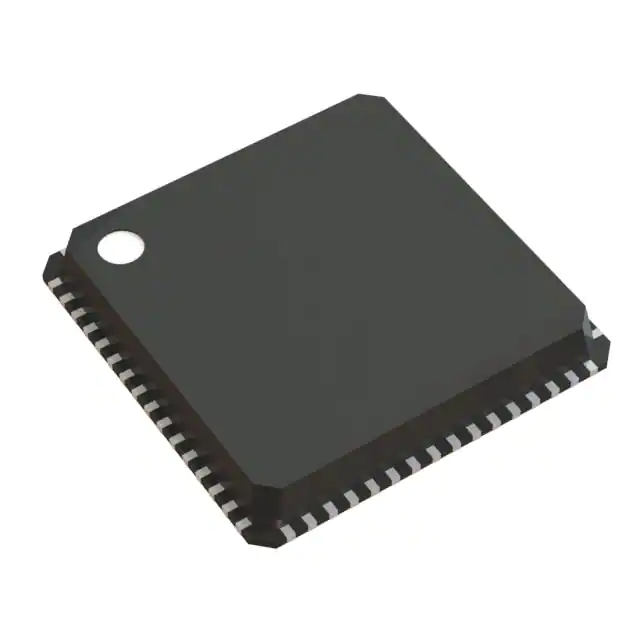
- Part No.:
- SI5341C-D-GM
- Manufacturer:
- Skyworks Solutions Inc.
- Package:
- 64-VFQFN Exposed Pad
- Datasheet:
-
 SI5341C-D-GM.pdf
- Description:
- IC JITTER ATTENUATOR/MULTIPLEXER
- Quantity:
- Payment:

- Shipping:

Inventory:4,556
Please send an inquiry. Send us your inquiry, and we will respond immediately.
Product details
Overview
SI5341C-D-GM from Skyworks Solutions is a 10-output, integer-only clock generator with ultra-low 90 fs rms phase jitter, supporting differential output frequencies from 100 Hz to 1028 MHz and LVCMOS up to 250 MHz. It features 4 input clocks (XA/XB crystal or IN0–IN2), programmable LVDS/LVPECL/CML/HCSL/LVCMOS outputs, and operates across –40 to +85 °C in a 64-QFN 9×9 mm package - deployed in FPGA clock trees, Ethernet switches, and OTN processors.
For engineers reviewing the SI5341C-D-GM datasheet, SI5341C-D-GM pinout, SI5341C-D-GM application, or SI5341C-D-GM equivalent, this page delivers verified technical context, exact pin roles, real-world use-value per application, and two validated alternative parts - all grounded in Skyworks Rev D documentation and ordering guide data.
Technical Context
The SI5341C-D-GM implements a wide-band PLL paired with integer-only MultiSynth™ fractional synthesis, enabling any-frequency output generation from any input frequency without fractional-N artifacts. Its architecture supports independent configuration of all 10 outputs for format (LVDS, LVPECL, CML, HCSL, LVCMOS), voltage (1.8/2.5/3.3 V), and common-mode level.
It accepts inputs from 25–54 MHz crystals (XA/XB) or 10–750 MHz differential clocks (IN0–IN2, XA/XB), uses I²C/SPI for register-based control, and includes non-volatile OTP memory for power-up configuration. Zero-delay mode and glitchless on-the-fly frequency changes are supported via dedicated registers and pins.
Key Specifications
| Parameter | Value and Actual Design Meaning |
|---|---|
| Output count | 10 fully independent differential or LVCMOS outputs - replaces multiple discrete clock ICs in complex clock trees. |
| Phase jitter (rms) | 90 fs over 12 kHz–20 MHz - meets stringent SerDes and high-speed ADC/DAC timing requirements. |
| Output frequency range | Differential: 100 Hz–1028 MHz; LVCMOS: 100 Hz–250 MHz - covers baseband, PCIe Gen5, DDR5, and OTU4 rates. |
| Input support | Crystal (25–54 MHz) or differential clock (10–750 MHz) on XA/XB/IN0–IN2 - enables flexible reference sourcing without external buffers. |
| Synthesis mode | Integer-only (no fractional-N) - eliminates spurs associated with fractional dividers, critical for RF and test equipment. |
| Supply voltages | VDD = 1.8 V ±5%, VDDA = 3.3 V ±5%, independent VDDO per output - allows mixed-voltage system interfacing without level shifters. |
| Package & temp | 64-QFN 9×9 mm, –40 to +85 °C - compatible with industrial and telecom PCB assembly standards. |
Pinout & Package
SI5341C-D-GM is housed in a 64-pin QFN package (9 mm × 9 mm, 0.5 mm pitch) with exposed thermal pad. Pin functions are defined per Skyworks Si5341 Rev D datasheet Section 9 (Pin Descriptions) and Figure 10.1 (package diagram).
| Pin/Terminal | Circuit Role | Design Meaning |
|---|---|---|
| XA, XB | Crystal oscillator input / differential clock input | Accepts 25–54 MHz crystal or differential clock; internal oscillator enabled by register; supports frequency adjustment ±1000 ppm. |
| IN0, IN0b, IN1, IN1b, IN2, IN2b | Differential input clock terminals | Support 10–750 MHz differential signals; configurable as primary reference sources with LOS monitoring. |
| OUT0–OUT9, OUT0b–OUT9b | Differential clock outputs | 10 independently configurable outputs; each supports LVDS/LVPECL/CML/HCSL/LVCMOS with programmable amplitude and VCM. |
| FB_IN, FB_INb | External feedback input for zero-delay mode | Enables fixed-minimum-delay operation when connected to selected output (e.g., OUT9); requires AC coupling and differential termination. |
| OEb | Global output enable/disable control | Active-low pin disables all outputs synchronously; individual outputs can be disabled via register control. |
| I²C_SCL, I²C_SDA / SPI_CSb, SPI_SCLK, SPI_MOSI, SPI_MISO | Serial interface terminals | I²C or SPI selection via I²C_SEL pin; supports in-circuit programming and runtime reconfiguration without reset. |
| VDD, VDDA, VDDO0–VDDO9 | Power supply pins | VDD (1.8 V core), VDDA (3.3 V analog), and per-output VDDO (1.8/2.5/3.3 V) enable mixed-signal voltage domain isolation. |
Key Features
| Feature | Design Value |
|---|---|
| Integer-only synthesis mode | Eliminates fractional-N spurs; ensures clean spectral purity for RF sampling and coherent optical systems. |
| Programmable output formats | Each of 10 outputs supports LVDS, LVPECL, CML, HCSL, or LVCMOS - removes need for external signal translators. |
| Zero-delay mode | Configurable via FB_IN feedback path to cancel internal propagation delay - critical for deterministic latency in packet processing. |
| Glitchless on-the-fly frequency change | Enables dynamic clock scaling (e.g., CPU DVFS or FIFO rate matching) without output interruption or metastability. |
| In-circuit NVM programming | Two-time OTP write capability stores custom startup configuration - eliminates boot-time serial interface dependency. |
Applications
| High-Speed FPGA Clocking | Ethernet Switch Timing |
|---|---|
|
Use Scenario: Providing synchronized clocks to multiple FPGA banks (GT transceivers, logic fabric, memory controllers) in 100G/400G switch line cards. IC Role / Device Role / Timing Role: Central clock tree generator replacing 5+ discrete oscillators and buffers; delivers 156.25 MHz, 312.5 MHz, and 1.25 GHz simultaneously with sub-100 fs jitter. Use Value: Reduces BOM count and layout area while meeting IEEE 802.3bj jitter budgets for KR/KP FEC lanes. |
Use Scenario: Clocking multi-port Ethernet PHYs, MACs, and packet processors in enterprise and data center switches. IC Role / Device Role / Timing Role: Generates IEEE 1588 PTP grandmaster clock (10 MHz), 125 MHz SGMII, and 156.25 MHz XAUI from single crystal reference. Use Value: Enables deterministic timestamp alignment across ports with <1 ns skew between outputs. |
| OTN Framer/Mapper Systems | Broadcast Video Processing |
|
Use Scenario: Supplying precise frame-aligned clocks to OTU2/OTU3/OTU4 framers, mappers, and forward error correction (FEC) engines. IC Role / Device Role / Timing Role: Synthesizes 1.244 Gbps, 2.488 Gbps, and 10.709 Gbps line rates with 0 ppm frequency error and <50 fs integrated jitter. Use Value: Meets ITU-T G.709 jitter tolerance masks without external jitter cleaners. |
Use Scenario: Generating genlock, pixel, and audio sample clocks for 4K/8K video encoders, SDI serializers, and HDMI transmitters. IC Role / Device Role / Timing Role: Delivers SMPTE ST 2059-2 compliant 27 MHz, 74.25 MHz, and 148.5 MHz clocks with <1 ps period jitter. Use Value: Prevents frame sync loss and audio-video desynchronization in broadcast infrastructure. |
Equivalent & Alternatives
The following parts are listed as comparable options for similar clock generator applications.
| Alternative Part | Technical Difference | Application Difference | Selection Advice |
|---|---|---|---|
| Si5341A-D-GM | Supports both integer and fractional synthesis; higher spurious content in fractional mode. | Better suited for multi-standard systems requiring non-integer ratios (e.g., USB + PCIe + DisplayPort). | Select Si5341A-D-GM only if fractional-N flexibility is required; SI5341C-D-GM preferred for lowest spurs in pure integer applications. |
| LMK04832RHAR | Two-stage PLL architecture; 11 outputs; RMS jitter 95 fs; supports JESD204B subclass 1. | Optimized for JESD204B-compliant data converters; includes SYSREF distribution and deterministic latency. | Choose LMK04832RHAR for RF/data converter timing; SI5341C-D-GM for general-purpose, low-spur clock tree consolidation. |
Compared with Si5341A-D-GM and LMK04832RHAR, the SI5341C-D-GM uniquely combines integer-only synthesis (zero fractional spurs), 10-output flexibility, and Skyworks' ClockBuilder Pro factory pre-programming - making it optimal for telecom and broadcast systems where spectral purity and deterministic startup are mandatory.
Availability
SI5341C-D-GM is available at Aetrix Electronics and suitable for FPGA clocking, Ethernet switching, and OTN framer applications requiring stable component supply, long-term lifecycle assurance, and traceable sourcing from authorized channels.
Supply support for SI5341C-D-GM includes scheduled delivery planning, volume procurement assistance, BOM continuity management, traceable sourcing, and lifecycle availability coordination for OEM customers, industrial embedded developers, connected-device designers, and electronics production programs.
Manufacturer
Skyworks Solutions is a global leader in analog and mixed-signal semiconductors, specializing in RF, timing, and precision analog components for communications, automotive, and industrial markets.
The SI5341C-D-GM belongs to Skyworks' Si5341/40 family of any-frequency clock generators, designed specifically to consolidate complex clock trees in high-speed digital systems while delivering ultra-low jitter and field-programmable flexibility.
FAQ
What is the key functional distinction between SI5341C-D-GM and SI5341A-D-GM?
The SI5341C-D-GM is configured for integer-only frequency synthesis, eliminating fractional-N spurs and ensuring superior spectral purity. In contrast, SI5341A-D-GM supports both integer and fractional modes - useful for non-integer ratios but introducing potential spurs. This makes SI5341C-D-GM ideal for RF, broadcast, and OTN applications where clean spectra are mandatory. The SI5341C-D-GM retains identical pinout, package, and feature set otherwise.
Does SI5341C-D-GM support zero-delay mode, and how is it implemented?
Yes, SI5341C-D-GM supports zero-delay mode via external feedback to the FB_IN/FB_INb pins. To activate it, the internal feedback loop is opened in software, and one output (typically OUT9) is routed back differentially and AC-coupled to FB_IN. This cancels internal propagation delay, achieving fixed, minimum latency between input and output - essential for deterministic packet processing and time-sensitive networking. Configuration is done through ClockBuilder Pro or direct register writes.
Can SI5341C-D-GM generate LVCMOS outputs, and what voltage levels are supported?
Yes, SI5341C-D-GM supports LVCMOS outputs on all 10 channels. Each output has its own VDDO pin, allowing independent selection of 1.8 V, 2.5 V, or 3.3 V swing. LVCMOS drive strength is configurable via register (OUTx_CMOS_DRV), with nominal impedances ranging from 22 Ω to 46 Ω depending on VDDO and setting. This enables direct interfacing with diverse logic families without external level shifters or series resistors.
What serial interfaces does SI5341C-D-GM support, and how is mode selection handled?
SI5341C-D-GM supports both I²C and SPI interfaces. Mode selection is controlled by the I²C_SEL pin: logic high selects I²C (SCL/SDA), logic low selects SPI (CSb/SCLK/MOSI/MISO). Both interfaces operate at standard speeds (I²C up to 400 kHz, SPI up to 25 MHz) and support full register access for configuration, status monitoring, and in-circuit NVM programming. Host voltage compatibility includes 1.8 V and 3.3 V logic levels.
Is factory pre-programming available for SI5341C-D-GM, and what does it entail?
Yes, factory pre-programming is available for SI5341C-D-GM using Skyworks' ClockBuilder Pro software. Users define their clock plan (input/output frequencies, formats, slew rates), and ClockBuilder Pro generates a custom part number (e.g., Si5341C-Dxxxxx-GM) with the configuration fused into OTP memory. The device powers up generating clocks immediately - no external programming required. Pre-programmed units ship with full datasheet addenda and are qualified for production use.
SI5341C-D-GM Specifications
- Product attributes
- Attribute value
- Manufacturer:
- Skyworks Solutions Inc.
- Series:
- -
- Package/Case:
- 64-VFQFN Exposed Pad
- Packaging:
- Tray
- Product Status:
- Active
- Programmable:
- Not Verified
- Type:
- -
- PLL:
- Yes
- Input:
- LVCMOS, LVDS, LVPECL, Crystal
- Output:
- CML, HCSL, LVCMOS, LVDS, LVPECL
- Number of Circuits:
- 1
- Ratio - Input:Output:
- 4:10
- Differential - Input:Output:
- Yes/Yes
- Frequency - Max:
- 1.028GHz
- Divider/Multiplier:
- Yes/No
- Voltage - Supply:
- 1.71V ~ 3.47V
- Operating Temperature:
- -40°C ~ 85°C
- Mounting Type:
- Surface Mount
- Grade:
- -
- Qualification:
- -
- Supplier Device Package:
- 64-QFN (9x9)
SI5341C-D-GM FAQ
1.How can I place an order for SI5341C-D-GM through Aetrix?
Please submit a Request for Quotation (RFQ) for SI5341C-D-GM on Aetrix. Our sales agent will provide a competitive quotation and guide you through the order confirmation once you accept the terms.
2.Are the price and stock information for SI5341C-D-GM reliable?
The price and inventory of SI5341C-D-GM are updated periodically and may fluctuate due to market conditions. Stock and pricing data are typically refreshed every 24 hours. Quotation validity for SI5341C-D-GM is usually 5 days.
3.What payment methods are accepted for SI5341C-D-GM?
We accept Wire Transfer, PayPal, Credit Card, Western Union, MoneyGram, and Escrow for SI5341C-D-GM transactions.
Note: Certain payment methods may incur a processing fee.
4.How is shipping managed for SI5341C-D-GM?
SI5341C-D-GM orders can be shipped via leading logistics carriers, including DHL, UPS, FedEx, TNT, or Registered Mail.
Once your SI5341C-D-GM order is processed, you will receive an email with the shipment details and tracking number.
Note: Tracking information may take up to 24 hours to appear. Express delivery typically takes 3–5 business days.
5.How can I obtain technical support or documentation for SI5341C-D-GM?
For technical support, including SI5341C-D-GM datasheets, pinout diagrams, or application guidance, please contact our engineering support team. They can provide detailed documentation and assistance for your SI5341C-D-GM requirements.
6.How does Aetrix verify that SI5341C-D-GM is sourced from the original manufacturer or authorized distributors?
All SI5341C-D-GM products on Aetrix are procured from qualified distributors and authorized channels. Our dedicated quality assurance team conducts strict verification, including traceability checks and, if necessary, third-party testing. This ensures that SI5341C-D-GM meets industry standards.
7.What is the process for return or replacement of SI5341C-D-GM?
All SI5341C-D-GM units undergo pre-shipment inspection (PSI). If there is an issue with SI5341C-D-GM, returns or replacements are accepted under the following conditions:
1.Quantity discrepancies, incorrect items, or visible external defects (such as breakage or corrosion), acknowledged by Aetrix.
2.The issue is reported within 90 days of delivery.
3.The SI5341C-D-GM part is unused and in its original packaging.
Return procedure for SI5341C-D-GM:
1.Submit a request within 90 days.
2.Obtain a Return Material Authorization (RMA) from Aetrix.
SI5341C-D-GM Tags

-
CD74HCT4046AM96
Texas Instruments

-
MC14046BDWR2G
onsemi

-
501MILFT
Renesas
-
CD74HC7046AM
Texas Instruments

-
CDCVF2505PWR
Texas Instruments

-
RC19004A100GNL#KB0
Renesas
-
SI5351A-B-GTR
Skyworks Solutions Inc.
-
CY2305SXI-1T
Infineon Technologies
-
570BILFT
Renesas

-
CDCE913PWR
Texas Instruments
-
CY2305SXI-1HT
Infineon Technologies

-
DS1086LU+T
Analog Devices Inc./Maxim Integrated
Tech Hub

Counterfeit components can hide behind convincing markings and passing basic function tests. This engineering reference covers source traceability, external inspection, X-ray, XRF, electrical testing, …

A practical engineering and sourcing framework covering lifecycle verification, lifetime-buy calculations, replacement qualification, supplier checks and counterfeit-risk controls.

TTL and CMOS logic families differ in thresholds, loading, output drive, power and timing. This engineering guide compares 74HC and 74HCT, calculates noise margins and checks 3.3 V/5 V compatibility.

A practical engineering guide to 3.3V and 5V logic compatibility, input thresholds, resistor dividers, translator ICs, MOSFET level shifting, I2C pull-ups, timing limits and power-sequencing risks.

The 74HC595 uses push-pull logic outputs, while the TPIC6B595 uses 50 V open-drain DMOS sinks for higher-power loads. This guide compares timing, current limits, 3.3 V interfacing, load wiring, thermal…

The 74HC595 converts serial data into eight stable parallel outputs. This guide covers pin functions, shift and storage timing, OE and MR behavior, drive-current limits, cascading, voltage compatibilit…

A technical comparison of level-sensitive latches and edge-triggered flip-flops, covering timing windows, setup and hold limits, master–slave operation, time borrowing, race-through, HDL inference and…

A D latch stores one bit while Enable controls when data can pass. This reference covers gate-level operation, truth tables, transparency, setup and hold timing, LE versus OE, common ICs and practical …

An SR latch stores one bit through cross-coupled feedback. This engineering reference covers NOR and NAND implementations, truth tables, forbidden-state recovery, gated operation, switch debouncing, fa…

Latch circuits retain one bit through feedback. This technical reference covers SR and D latches, truth tables, transparency, timing limits, latch-versus-flip-flop behavior, applications and common log…


