
 My Inquiry
 My Account


Skyworks Solutions Inc. SI5364-F-BC
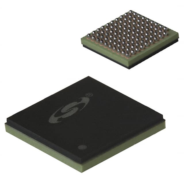
- Part No.:
- SI5364-F-BC
- Manufacturer:
- Skyworks Solutions Inc.
- Package:
- 99-BCBGA
- Datasheet:
-
 SI5364-F-BC.pdf
- Description:
- IC CLOCK GENERATOR 99CBGA
- Quantity:
- Payment:

- Shipping:

Inventory:1,491
Please send an inquiry. Send us your inquiry, and we will respond immediately.
Product details
Overview
SI5364-F-BC from Silicon Laboratories is a SONET/SDH precision port card clock IC that phase-locks to one of three 19.44 MHz reference inputs and generates four independent ultra-low-jitter clock outputs at 19.44, 155.52, or 622.08 MHz. It implements DSPLL™ technology with no external loop filter components, supports Stratum 3/3E and SMC-compliant hitless switching, and delivers 0.26 psRMS (50 kHz–80 MHz) jitter generation. It is deployed in OC-192/OC-48 line cards requiring telecom-grade timing integrity.
For engineers reviewing the SI5364-F-BC datasheet, SI5364-F-BC pinout, SI5364-F-BC application, or SI5364-F-BC equivalent, key selection considerations include its 4-output synchronous clock synthesis capability, selectable 800–6400 Hz PLL bandwidth, FEC rate scaling (255/238 or 238/255), digital hold mode with ±7 ppm initial accuracy, and compliance with Telcordia GR-1244-CORE phase transient limits.
Technical Context
The SI5364-F-BC integrates a digitally controlled DSPLL with programmable loop bandwidth (800/1600/3200/6400 Hz via BWSEL[1:0]), enabling precise trade-offs between jitter attenuation and generation. Its input monitoring circuitry provides loss-of-signal (LOS) and frequency offset (FOS) alarms for each of three differential clock inputs (CLKIN_A, CLKIN_B, REF/CLKIN_F), supporting automatic revertive/non-revertive switching with sub-200 ps phase step magnitude.
Each of the four differential clock outputs (CLKOUT_1 to CLKOUT_4) is independently configured via FRQSEL_[1:0] pins for 1×, 8×, or 32× multiplication of the selected input clock, with optional FEC scaling applied globally via FEC[1:0]. The device includes an 8 kHz frame sync output (FSYNC), SYNCIN alignment input, and digital hold functionality activated on input loss, maintaining output frequency within ±30 ppm/°C drift.
Key Specifications
| Parameter | Value and Actual Design Meaning |
|---|---|
| Supply Voltage | 3.3 V ±5% - single-rail operation eliminates need for dual supplies or LDOs in telecom line cards. |
| Output Jitter (RMS) | 0.26 ps (50 kHz–80 MHz) - meets OC-192/SDH STM-64 jitter generation requirements per ITU-T G.823. |
| Input Frequency Range | 18.14–22.60 MHz - supports non-FEC (19.44 MHz), forward FEC (18.14 MHz), and reverse FEC (20.82 MHz) references. |
| Phase Step (Switching) | ±200 ps max - ensures MTIE compliance during hitless clock rearrangement per Telcordia GR-1244-CORE. |
| Digital Hold Accuracy | ±7 ppm initial, ±16.2 ppm/°C drift - sustains Stratum 3E timing stability during extended input loss events. |
| Package | 11 × 11 mm CBGA - compact footprint compatible with high-density port card layouts and thermal management at 20 °C/W θJA. |
Pinout & Package
The SI5364-F-BC is housed in an 11 × 11 mm, 64-pin CBGA package with exposed thermal pad. Pin assignments follow the bottom-view layout defined in Silicon Labs Rev. 2.2 datasheet Section 3 and Figure 7.
| Pin/Terminal | Circuit Role | Design Meaning |
|---|---|---|
| CLKIN_A+, CLKIN_A− | Differential clock input A | Accepts 19.44 MHz reference; supports ac-coupled single-ended drive with unused pin grounded. |
| CLKIN_B+, CLKIN_B− | Differential clock input B | Redundant 19.44 MHz input; monitored for LOS/FOS relative to REF/CLKIN_F for automatic switching. |
| REF/CLKIN_F+, REF/CLKIN_F− | Reference/fallback clock input | Serves as third clock source and frequency reference for FOS comparison; enables SMC/Stratum 3E compliance. |
| CLKOUT_1+ to CLKOUT_4− | Four differential clock outputs | Each pair independently configurable for 19.44/155.52/622.08 MHz; 100 Ω load, 816–1100 mVPP swing. |
| BWSEL[1:0] | PLL loop bandwidth select | Sets jitter transfer cutoff at 800/1600/3200/6400 Hz - critical for optimizing system-level jitter budget allocation. |
| FEC[1:0] | FEC scaling control | Selects 1/1, 255/238, or 238/255 clock scaling - required for interoperability with FEC-aware SONET/SDH systems. |
| RSTN/CAL | Reset and calibration trigger | Active-low asynchronous reset; initiates internal DSPLL self-calibration sequence upon rising edge. |
| FSYNC | 8 kHz frame sync output | Provides synchronous timing marker aligned to output clocks - used for frame boundary alignment in SDH mapping. |
Key Features
| Feature | Design Value |
|---|---|
| No external loop filter components | DSPLL™ eliminates analog RC networks, reducing BOM count, board area, and sensitivity to layout parasitics. |
| Hitless clock switching | Automatic/manual input selection with <400 ps output phase skew - prevents packet loss during reference switchover. |
| Programmable PLL bandwidth | Four discrete BWSEL settings allow tuning jitter attenuation vs. generation for specific network layer requirements. |
| FEC rate compatibility | 255/238 and 238/255 scaling modes enable seamless integration into forward-error-corrected transport systems. |
| Digital hold mode | Maintains output frequency within ±7 ppm for first 100 ms after input loss - satisfies Stratum 3E holdover stability mandates. |
Applications
| SONET/SDH Line Cards | Terabit Core Routers |
|---|---|
Use Scenario: Generating synchronized 19.44 MHz, 155.52 MHz, and 622.08 MHz clocks for OC-192/STM-64 framer, mapper, and SERDES interfaces on a single port card. IC Role / Device Role / Timing Role: Precision clock generator and switch providing Stratum 3E-compliant timing with hitless failover between redundant references. Use Value: Enables single-chip timing solution meeting GR-1244-CORE MTIE and jitter transfer requirements without external filters or calibration circuitry. | Use Scenario: Distributing low-jitter clocks across multiple line cards and switch fabric ASICs in carrier-grade routers handling >1 Tbps throughput. IC Role / Device Role / Timing Role: Centralized clock synthesizer delivering four phase-aligned outputs with <400 ps inter-output skew. Use Value: Reduces system-level jitter accumulation across cascaded clock domains, improving BER in 10G/40G/100G Ethernet and OTU interfaces. |
| Digital Cross-Connect Systems | Core Switches |
Use Scenario: Providing timing for TDM switching matrices and channelized interface modules requiring strict wander and jitter control per G.783. IC Role / Device Role / Timing Role: Stratum 3/3E-compliant clock source with digital hold and frequency offset alarm support for network synchronization integrity. Use Value: Ensures continuity of service during reference failures by maintaining holdover accuracy within ±30 ppm over temperature and supply variation. | Use Scenario: Clocking high-speed SerDes lanes and packet buffer controllers in modular chassis-based switches with hot-swappable line cards. IC Role / Device Role / Timing Role: Multi-output clock generator supporting both FEC and non-FEC rates for mixed-interface backplanes. Use Value: Eliminates need for separate clock ICs for different rate families, simplifying BOM and enabling dynamic rate reconfiguration via pin strapping. |
Equivalent & Alternatives
The following parts are listed as comparable options for similar precision clock generation applications.
| Alternative Part | Technical Difference | Application Difference | Selection Advice |
|---|---|---|---|
| Si5362-F-BC | 2-output version; identical DSPLL core, same jitter performance, but lacks two CLKOUT pairs and FSYNC output. | Targeted at cost-sensitive or space-constrained OC-48/STM-16 cards where only two clock domains are needed. | Select when four outputs and frame sync are not required - reduces PCB area and power by ~30%. |
| LMK04832ISQE/NOPB | Two-stage jitter cleaner with integrated VCO; higher power (350 mA), larger 9×9 mm QFN, and requires external loop filter for second stage. | Used in RF and instrumentation where ultra-low additive jitter (<0.15 psRMS) and programmable delay are prioritized over telecom compliance. | Choose for applications demanding sub-0.2 psRMS jitter and fine-grained output phase adjustment - not drop-in compatible. |
Compared with Si5362-F-BC, the SI5364-F-BC adds two clock outputs and FSYNC for full OC-192 port card coverage; compared with LMK04832ISQE/NOPB, it offers lower power, smaller footprint, and built-in telecom alarm logic but less flexible phase control.
Availability
SI5364-F-BC is available at Aetrix Electronics and suitable for SONET/SDH line cards, terabit routers, digital cross-connect systems, and core switches requiring stable component supply with full traceability and long-term lifecycle support.
Supply support for SI5364-F-BC includes scheduled delivery planning, volume procurement assistance, BOM continuity management, traceable sourcing, and lifecycle availability coordination for OEM customers, industrial embedded developers, connected-device designers, and electronics production programs.
Manufacturer
Silicon Laboratories is a fabless semiconductor company specializing in timing, wireless, and sensor solutions for communications, industrial, and consumer markets.
The SI5364-F-BC belongs to Silicon Labs' DSPLL™ precision clock IC product line, engineered specifically for telecom infrastructure applications requiring Stratum-grade timing, hitless switching, and FEC-aware clock synthesis.
FAQ
What is the primary function of the SI5364-F-BC in telecom systems?
The SI5364-F-BC serves as a precision clock generator and switch for SONET/SDH port cards, accepting up to three 19.44 MHz references and producing four independent, ultra-low-jitter outputs at 19.44/155.52/622.08 MHz. Its DSPLL™ architecture enables Stratum 3E-compliant timing with hitless switching, digital hold, and FEC scaling - all critical for OC-192/STM-64 line card reliability. The SI5364-F-BC replaces multi-chip timing solutions with a single, fully integrated IC.
Does the SI5364-F-BC require external loop filter components?
No, the SI5364-F-BC does not require external loop filter components. Its DSPLL™ technology replaces the analog loop filter with a digital signal processing algorithm that controls the VCO, eliminating sensitive analog nodes and reducing design complexity. This allows the SI5364-F-BC to achieve 0.26 psRMS jitter generation (50 kHz–80 MHz) while simplifying PCB layout and improving immunity to board-level noise - a key advantage over traditional analog PLLs.
How does the SI5364-F-BC support FEC rate compatibility?
The SI5364-F-BC supports FEC rate compatibility through its FEC[1:0] control inputs, which apply global 255/238 or 238/255 scaling to all active clock outputs. For example, a 622.08 MHz non-FEC output becomes 666.51 MHz (255/238 × 622.08) when FEC[1:0] = 01, or a 20.83 MHz FEC input yields 622.08 MHz when FEC[1:0] = 10. This ensures interoperability with forward-error-corrected transport layers without requiring external dividers or multipliers - a core capability of the SI5364-F-BC.
What is the significance of the BWSEL[1:0] pins on the SI5364-F-BC?
The BWSEL[1:0] pins on the SI5364-F-BC select one of four discrete PLL loop bandwidths: 800 Hz, 1600 Hz, 3200 Hz, or 6400 Hz. This setting directly governs jitter transfer attenuation, phase transient slope, and jitter generation trade-offs. A lower bandwidth (e.g., 800 Hz) strongly attenuates incoming jitter but increases generated jitter; a higher bandwidth (e.g., 6400 Hz) improves tracking but reduces filtering. Engineers configure BWSEL[1:0] to match system-level jitter budgets - a defining feature of the SI5364-F-BC's adaptability.
Can the SI5364-F-BC maintain timing during loss of all reference clocks?
Yes, the SI5364-F-BC enters digital hold mode upon loss of all valid clock inputs, sustaining output frequency with ±7 ppm initial accuracy (first 100 ms) and ±16.2 ppm/°C drift over temperature. Its internal calibration and DSPLL architecture ensure holdover stability meets Stratum 3E requirements for telecom infrastructure. This capability is integral to the SI5364-F-BC's role in mission-critical systems where uninterrupted timing is mandatory during reference failures.
SI5364-F-BC Specifications
- Product attributes
- Attribute value
- Manufacturer:
- Skyworks Solutions Inc.
- Series:
- DSPLL®
- Package/Case:
- 99-BCBGA
- Packaging:
- Tray
- Product Status:
- Obsolete
- Programmable:
- Not Verified
- Type:
- Clock Generator
- PLL:
- Yes
- Input:
- Clock
- Output:
- CML
- Number of Circuits:
- 1
- Ratio - Input:Output:
- 3:4
- Differential - Input:Output:
- Yes/Yes
- Frequency - Max:
- 675MHz
- Divider/Multiplier:
- No/Yes
- Voltage - Supply:
- 3.135V ~ 3.465V
- Operating Temperature:
- -20°C ~ 85°C
- Mounting Type:
- Surface Mount
- Grade:
- -
- Qualification:
- -
- Supplier Device Package:
- 99-CBGA (11x11)
SI5364-F-BC FAQ
1.How can I place an order for SI5364-F-BC through Aetrix?
Please submit a Request for Quotation (RFQ) for SI5364-F-BC on Aetrix. Our sales agent will provide a competitive quotation and guide you through the order confirmation once you accept the terms.
2.Are the price and stock information for SI5364-F-BC reliable?
The price and inventory of SI5364-F-BC are updated periodically and may fluctuate due to market conditions. Stock and pricing data are typically refreshed every 24 hours. Quotation validity for SI5364-F-BC is usually 5 days.
3.What payment methods are accepted for SI5364-F-BC?
We accept Wire Transfer, PayPal, Credit Card, Western Union, MoneyGram, and Escrow for SI5364-F-BC transactions.
Note: Certain payment methods may incur a processing fee.
4.How is shipping managed for SI5364-F-BC?
SI5364-F-BC orders can be shipped via leading logistics carriers, including DHL, UPS, FedEx, TNT, or Registered Mail.
Once your SI5364-F-BC order is processed, you will receive an email with the shipment details and tracking number.
Note: Tracking information may take up to 24 hours to appear. Express delivery typically takes 3–5 business days.
5.How can I obtain technical support or documentation for SI5364-F-BC?
For technical support, including SI5364-F-BC datasheets, pinout diagrams, or application guidance, please contact our engineering support team. They can provide detailed documentation and assistance for your SI5364-F-BC requirements.
6.How does Aetrix verify that SI5364-F-BC is sourced from the original manufacturer or authorized distributors?
All SI5364-F-BC products on Aetrix are procured from qualified distributors and authorized channels. Our dedicated quality assurance team conducts strict verification, including traceability checks and, if necessary, third-party testing. This ensures that SI5364-F-BC meets industry standards.
7.What is the process for return or replacement of SI5364-F-BC?
All SI5364-F-BC units undergo pre-shipment inspection (PSI). If there is an issue with SI5364-F-BC, returns or replacements are accepted under the following conditions:
1.Quantity discrepancies, incorrect items, or visible external defects (such as breakage or corrosion), acknowledged by Aetrix.
2.The issue is reported within 90 days of delivery.
3.The SI5364-F-BC part is unused and in its original packaging.
Return procedure for SI5364-F-BC:
1.Submit a request within 90 days.
2.Obtain a Return Material Authorization (RMA) from Aetrix.
SI5364-F-BC Tags

-
CD74HCT4046AM96
Texas Instruments

-
MC14046BDWR2G
onsemi

-
501MILFT
Renesas
-
CD74HC7046AM
Texas Instruments

-
CDCVF2505PWR
Texas Instruments

-
RC19004A100GNL#KB0
Renesas
-
SI5351A-B-GTR
Skyworks Solutions Inc.
-
CY2305SXI-1T
Infineon Technologies
-
570BILFT
Renesas

-
CDCE913PWR
Texas Instruments
-
CY2305SXI-1HT
Infineon Technologies

-
DS1086LU+T
Analog Devices Inc./Maxim Integrated
Tech Hub

Counterfeit components can hide behind convincing markings and passing basic function tests. This engineering reference covers source traceability, external inspection, X-ray, XRF, electrical testing, …

A practical engineering and sourcing framework covering lifecycle verification, lifetime-buy calculations, replacement qualification, supplier checks and counterfeit-risk controls.

TTL and CMOS logic families differ in thresholds, loading, output drive, power and timing. This engineering guide compares 74HC and 74HCT, calculates noise margins and checks 3.3 V/5 V compatibility.

A practical engineering guide to 3.3V and 5V logic compatibility, input thresholds, resistor dividers, translator ICs, MOSFET level shifting, I2C pull-ups, timing limits and power-sequencing risks.

The 74HC595 uses push-pull logic outputs, while the TPIC6B595 uses 50 V open-drain DMOS sinks for higher-power loads. This guide compares timing, current limits, 3.3 V interfacing, load wiring, thermal…

The 74HC595 converts serial data into eight stable parallel outputs. This guide covers pin functions, shift and storage timing, OE and MR behavior, drive-current limits, cascading, voltage compatibilit…

A technical comparison of level-sensitive latches and edge-triggered flip-flops, covering timing windows, setup and hold limits, master–slave operation, time borrowing, race-through, HDL inference and…

A D latch stores one bit while Enable controls when data can pass. This reference covers gate-level operation, truth tables, transparency, setup and hold timing, LE versus OE, common ICs and practical …

An SR latch stores one bit through cross-coupled feedback. This engineering reference covers NOR and NAND implementations, truth tables, forbidden-state recovery, gated operation, switch debouncing, fa…

Latch circuits retain one bit through feedback. This technical reference covers SR and D latches, truth tables, transparency, timing limits, latch-versus-flip-flop behavior, applications and common log…


