
 My Inquiry
 My Account


NXP Semiconductors SJA1000T/N1,112
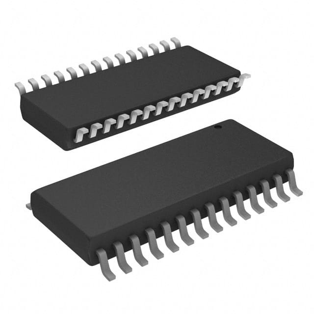
- Part No.:
- SJA1000T/N1,112
- Manufacturer:
- NXP Semiconductors
- Category:
- Controllers
- Package:
- 28-SOIC (0.295", 7.50mm Width)
- Datasheet:
-
 SJA1000T/N1,112.pdf
- Description:
- IC STAND-ALONE CAN CTRLR 28-SOIC
- Quantity:
- Payment:

- Shipping:

Inventory:3,029
Please send an inquiry. Send us your inquiry, and we will respond immediately.
Product details
Overview
SJA1000T/N1,112 from NXP Semiconductors (formerly Philips) is a stand-alone CAN 2.0B controller IC supporting both BasicCAN and PeliCAN modes, with 64-byte RX FIFO, 1 Mbit/s bit rate, 24 MHz clock input, and −40 to +125 °C operating temperature - used in automotive body control modules for robust vehicle network communication.
For engineers reviewing the SJA1000T/N1,112 datasheet, SJA1000T/N1,112 pinout, SJA1000T/N1,112 application, or SJA1000T/N1,112 equivalent, key selection considerations include CAN 2.0B protocol support, dual-mode register compatibility, programmable bus timing, open-drain INT output, and SO28 package suitability for space-constrained industrial CAN nodes.
Technical Context
The SJA1000T/N1,112 implements two distinct operational modes: BasicCAN (PCA82C200-compatible, default on reset) for legacy 11-bit identifier support, and PeliCAN mode enabling full CAN 2.0B compliance including 29-bit identifiers, error counters with read/write access, and arbitration lost capture with bit-position detail.
Its architecture integrates Interface Management Logic (IML), Bit Stream Processor (BSP), Bit Timing Logic (BTL) with programmable synchronization jump width and time segments, and Error Management Logic (EML) - all synchronized to a 24 MHz crystal oscillator and configurable via BTR0/BTR1 registers for precise bit timing calibration across varying bus lengths and node counts.
Key Specifications
| Parameter | Value and Actual Design Meaning |
|---|---|
| CAN Protocol | CAN 2.0B compliant: supports both standard (11-bit) and extended (29-bit) frame formats in PeliCAN mode; tolerates extended frames passively in BasicCAN mode |
| Max Bit Rate | 1 Mbit/s: enables high-speed diagnostics and real-time control messaging on short-to-medium automotive/industrial CAN buses |
| Receive Buffer | 64-byte RX FIFO: allows CPU to process one message while up to 64 bytes of subsequent messages are buffered, reducing overrun risk in burst-traffic scenarios |
| Operating Temp | −40 to +125 °C: qualified for under-hood automotive ECUs and industrial motor drives requiring extended thermal resilience |
| Interface Mode | Configurable Intel/Motorola bus interface: MODE pin selects addressing/control signal behavior to match host MCU architecture without external logic |
| Interrupt Output | Open-drain INT (active LOW): supports wired-OR connection with multiple CAN controllers or peripherals for consolidated interrupt handling |
| Crystal Input | 24 MHz XTAL1/XTAL2: provides stable clock source for internal oscillator; supports external clock injection when XTAL2 is left open |
Pinout & Package
Package: SO28 (plastic small outline, 28 leads, 7.5 mm body width, SOT136-1).
| Pin/Terminal | Circuit Role | Design Meaning |
|---|---|---|
| AD7–AD0 | Multiplexed address/data bus | 8-bit bidirectional bus shared between address and data transfers; requires external latch (e.g., 74HC373) in Intel mode |
| ALE/AS | Address latch enable / Address strobe | Demultiplexes AD[7:0] in Intel mode (ALE pulse); serves as address strobe in Motorola mode |
| CS | Chip select | Active LOW enables register access; must be asserted during all read/write cycles to SJA1000T/N1,112 |
| RD/E, WR | Read/Enable or Write control | RD/E is read strobe (Intel) or E-enable (Motorola); WR is write strobe (Intel) or RD/WR (Motorola) |
| INT | Interrupt output | Open-drain, active LOW interrupt signal; requires external pull-up; wakes CPU on status change or error event |
| RST | Reset input | Active LOW hardware reset; supports automatic power-on reset via RC network (e.g., 1 µF + 50 kΩ) |
| TX0, TX1 | CAN output drivers | Differential outputs driving external CAN transceiver (e.g., TJA1050); configured via OCR register for dominant/recessive polarity |
| RX0, RX1 | CAN input comparators | Differential inputs from transceiver; bypassable via CBP bit in CDR register to reduce propagation delay when external comparator is used |
Key Features
| Feature | Design Value |
|---|---|
| PeliCAN mode extensions | Enables full CAN 2.0B functionality: 29-bit ID support, error counters with read/write access, and arbitration lost capture with bit-level position reporting |
| Programmable output driver | OCR register configures TX0/TX1 transistor types (P/N), polarity, and output mode - allowing optimization for different transceiver topologies |
| Hot-plug bit rate detection | Software-driven auto-detection of bus bit rate during runtime, enabling dynamic reconfiguration without bus interruption |
| Listen-only mode | Disables ACK transmission and active error flags, permitting non-intrusive bus monitoring for diagnostic or logging applications |
| Single-shot transmission | Prevents automatic retransmission after arbitration loss or error - essential for time-triggered or safety-critical message scheduling |
Applications
| Automotive Body Control Unit | Industrial PLC CAN Gateway |
|---|---|
Use Scenario: Centralized control of door locks, lighting, wipers, and HVAC in modern vehicles using distributed CAN nodes. IC Role / Device Role / Timing Role: Stand-alone CAN controller managing message arbitration, filtering, and error handling between microcontroller and physical layer transceiver. Use Value: Enables deterministic 1 Mbit/s communication with −40 to +125 °C operation, meeting AEC-Q100 stress requirements for under-dash mounting locations. | Use Scenario: Bridging Modbus RTU field devices to higher-level SCADA systems via CANopen or custom CAN protocols in factory automation. IC Role / Device Role / Timing Role: Protocol translation engine interfacing ARM-based PLC CPU with CAN physical layer, handling frame assembly/disassembly and acceptance filtering. Use Value: 64-byte RX FIFO prevents message loss during high-throughput I/O scanning; PeliCAN mode supports extended IDs for device addressing in large networks. |
| Medical Equipment Diagnostic Port | Off-Highway Vehicle Telematics |
Use Scenario: Real-time diagnostics and firmware updates over service CAN port in imaging systems and infusion pumps. IC Role / Device Role / Timing Role: Isolated CAN interface controller ensuring reliable command/response exchange between host PC and embedded subsystems. Use Value: Listen-only mode allows passive logging of bus traffic without affecting system operation; hot-plug detection supports plug-and-play service tools. | Use Scenario: Telematics unit collecting engine, hydraulics, and GPS data from multiple CAN subnets on construction or agricultural machinery. IC Role / Device Role / Timing Role: Multi-channel CAN controller (with external multiplexer) aggregating data from J1939, ISO 11783, and proprietary vehicle networks. Use Value: Extended temperature range ensures reliability in unconditioned cab environments; single-shot transmission guarantees priority message delivery in safety-critical alerts. |
Equivalent & Alternatives
The following parts are listed as comparable options for similar CAN controller applications.
| Alternative Part | Technical Difference | Application Difference | Selection Advice |
|---|---|---|---|
| MCP2515-I/SO | SPI interface only; no parallel bus; requires external crystal (up to 25 MHz); no listen-only or hot-plug modes | Best suited for low-pin-count MCUs with SPI but no parallel bus; lacks PeliCAN-specific registers and error counter visibility | Select when board layout favors SPI connectivity and cost-sensitive designs tolerate reduced diagnostic visibility |
| TJA1050T/CM | Physical layer transceiver only - not a controller; requires external CAN controller (e.g., SJA1000T/N1,112) for protocol handling | Used downstream of SJA1000T/N1,112 to drive differential CAN_H/CAN_L lines; not functionally substitutable | Select as companion transceiver, not as controller alternative; verify voltage level and fault protection match system requirements |
Compared with MCP2515-I/SO and TJA1050T/CM, the SJA1000T/N1,112 uniquely delivers parallel-microprocessor integration, dual-mode CAN 2.0B compliance, and hardware-level error diagnostics - making it irreplaceable in legacy automotive and industrial designs requiring direct memory-mapped register access and deterministic interrupt latency.
Availability
SJA1000T/N1,112 is available at Aetrix Electronics and suitable for automotive body control units, industrial PLC gateways, medical diagnostic ports, and off-highway telematics systems requiring stable component supply across extended product lifecycles.
Supply support for SJA1000T/N1,112 includes scheduled delivery planning, volume procurement assistance, BOM continuity management, traceable sourcing, and lifecycle availability coordination for OEM customers, industrial embedded developers, connected-device designers, and electronics production programs.
Manufacturer
NXP Semiconductors is a global semiconductor leader focused on secure connectivity solutions for automotive, industrial, and IoT applications, with deep heritage in CAN technology dating to Philips' original PCA82C200.
The SJA1000T/N1,112 belongs to NXP's legacy CAN controller product line, designed specifically for robust, pin-compatible migration from PCA82C200 in automotive and industrial control systems requiring long-term availability and proven field reliability.
FAQ
What is the primary function of the SJA1000T/N1,112 in a CAN network?
The SJA1000T/N1,112 serves as a stand-alone CAN protocol controller that handles message framing, arbitration, error detection, and filtering - interfacing between a host microcontroller and an external CAN transceiver. It implements both BasicCAN and PeliCAN modes, enabling compatibility with legacy systems and full CAN 2.0B functionality. The SJA1000T/N1,112 does not include physical layer drivers; those require a separate transceiver such as TJA1050.
Does the SJA1000T/N1,112 support 29-bit extended CAN identifiers?
Yes, the SJA1000T/N1,112 supports 29-bit extended identifiers exclusively in PeliCAN mode. In BasicCAN mode (default on reset), it operates with 11-bit standard identifiers only and passively acknowledges extended frames without generating receive interrupts. To use extended IDs, software must configure the CAN-mode bit in the Clock Divider Register (CDR) to enter PeliCAN mode and initialize the corresponding acceptance filter registers.
What is the maximum bit rate supported by the SJA1000T/N1,112?
The SJA1000T/N1,112 supports a maximum bit rate of 1 Mbit/s, achievable with appropriate bus timing configuration using BTR0 and BTR1 registers and a 24 MHz crystal. Actual achievable bit rate depends on bus length, node count, and termination; for example, 500 kbit/s is typical for 100 m bus lengths, while 1 Mbit/s is validated for ≤40 m with proper impedance matching and stub minimization.
How does the SJA1000T/N1,112 handle power management and wake-up events?
The SJA1000T/N1,112 supports sleep mode via the Go-To-Sleep (GTS) command in the Command Register. It wakes automatically on bus activity (dominant level detected on RX0/RX1), INT pin assertion, or external RST deassertion. During wake-up, the oscillator restarts and a wake-up interrupt is generated. The SJA1000T/N1,112 maintains CLKOUT for ≥15 bit times after GTS activation to allow synchronized MCU standby entry.
Can the SJA1000T/N1,112 operate without an external crystal?
No, the SJA1000T/N1,112 requires an external 24 MHz crystal connected between XTAL1 and XTAL2 (with 15 pF load capacitors to VSS1), or an external 24 MHz clock signal applied to XTAL1 while leaving XTAL2 open. The internal oscillator cannot function without this timing source, and no internal RC oscillator is provided. Omitting the crystal or clock signal results in complete functional failure of the CAN controller logic.
SJA1000T/N1,112 Specifications
- Product attributes
- Attribute value
- Manufacturer:
- NXP Semiconductors
- Package/Case:
- 28-SOIC (0.295", 7.50mm Width)
- Programmable:
- Not Verified
- Protocol:
- CANbus
- Function:
- Controller
- Interface:
- Parallel
- Standards:
- CAN 2.0
- Voltage - Supply:
- 4.5V ~ 5.5V
- Current - Supply:
- 15mA
- Operating Temperature:
- -40°C ~ 125°C
- Supplier Device Package:
- 28-SO
- Grade:
- -
- Qualification:
- -
SJA1000T/N1,112 FAQ
1.How can I place an order for SJA1000T/N1,112 through Aetrix?
Please submit a Request for Quotation (RFQ) for SJA1000T/N1,112 on Aetrix. Our sales agent will provide a competitive quotation and guide you through the order confirmation once you accept the terms.
2.Are the price and stock information for SJA1000T/N1,112 reliable?
The price and inventory of SJA1000T/N1,112 are updated periodically and may fluctuate due to market conditions. Stock and pricing data are typically refreshed every 24 hours. Quotation validity for SJA1000T/N1,112 is usually 5 days.
3.What payment methods are accepted for SJA1000T/N1,112?
We accept Wire Transfer, PayPal, Credit Card, Western Union, MoneyGram, and Escrow for SJA1000T/N1,112 transactions.
Note: Certain payment methods may incur a processing fee.
4.How is shipping managed for SJA1000T/N1,112?
SJA1000T/N1,112 orders can be shipped via leading logistics carriers, including DHL, UPS, FedEx, TNT, or Registered Mail.
Once your SJA1000T/N1,112 order is processed, you will receive an email with the shipment details and tracking number.
Note: Tracking information may take up to 24 hours to appear. Express delivery typically takes 3–5 business days.
5.How can I obtain technical support or documentation for SJA1000T/N1,112?
For technical support, including SJA1000T/N1,112 datasheets, pinout diagrams, or application guidance, please contact our engineering support team. They can provide detailed documentation and assistance for your SJA1000T/N1,112 requirements.
6.How does Aetrix verify that SJA1000T/N1,112 is sourced from the original manufacturer or authorized distributors?
All SJA1000T/N1,112 products on Aetrix are procured from qualified distributors and authorized channels. Our dedicated quality assurance team conducts strict verification, including traceability checks and, if necessary, third-party testing. This ensures that SJA1000T/N1,112 meets industry standards.
7.What is the process for return or replacement of SJA1000T/N1,112?
All SJA1000T/N1,112 units undergo pre-shipment inspection (PSI). If there is an issue with SJA1000T/N1,112, returns or replacements are accepted under the following conditions:
1.Quantity discrepancies, incorrect items, or visible external defects (such as breakage or corrosion), acknowledged by Aetrix.
2.The issue is reported within 90 days of delivery.
3.The SJA1000T/N1,112 part is unused and in its original packaging.
Return procedure for SJA1000T/N1,112:
1.Submit a request within 90 days.
2.Obtain a Return Material Authorization (RMA) from Aetrix.
SJA1000T/N1,112 Tags

-
PTN5150AHXMP
NXP Semiconductors

-
USB3740B-AI9-TR
Microchip Technology

-
USB3740B-AI2-TR
Microchip Technology

-
USB3300-EZK-TR
Microchip Technology
-
USB3300-EZK
Microchip Technology

-
FUSB340TMX
onsemi

-
FUSB302BMPX
onsemi

-
DP83826IRHBR
Texas Instruments

-
MCP2518FDT-E/QBB
Microchip Technology
-
FUSB302MPX
onsemi

-
MCP2518FDT-E/SL
Microchip Technology

-
FT260Q-R
FTDI, Future Technology Devices International Ltd
Tech Hub

A practical engineering guide to 3.3V and 5V logic compatibility, input thresholds, resistor dividers, translator ICs, MOSFET level shifting, I2C pull-ups, timing limits and power-sequencing risks.

The 74HC595 uses push-pull logic outputs, while the TPIC6B595 uses 50 V open-drain DMOS sinks for higher-power loads. This guide compares timing, current limits, 3.3 V interfacing, load wiring, thermal…

The 74HC595 converts serial data into eight stable parallel outputs. This guide covers pin functions, shift and storage timing, OE and MR behavior, drive-current limits, cascading, voltage compatibilit…

A technical comparison of level-sensitive latches and edge-triggered flip-flops, covering timing windows, setup and hold limits, master–slave operation, time borrowing, race-through, HDL inference and…

A D latch stores one bit while Enable controls when data can pass. This reference covers gate-level operation, truth tables, transparency, setup and hold timing, LE versus OE, common ICs and practical …

An SR latch stores one bit through cross-coupled feedback. This engineering reference covers NOR and NAND implementations, truth tables, forbidden-state recovery, gated operation, switch debouncing, fa…

Latch circuits retain one bit through feedback. This technical reference covers SR and D latches, truth tables, transparency, timing limits, latch-versus-flip-flop behavior, applications and common log…

An engineering guide to LED driver operation, constant-current and constant-voltage outputs, linear and switching topologies, dimming, IC selection, calculations, replacement compatibility, and fault c…

Operational amplifier guide covering op amp basics, feedback, ideal vs real op amps, common configurations, buffer circuits, offset, bias current, gain-bandwidth, slew rate, rail-to-rail limits and sel…

Jumper cables guide covering safe connection order, red and black clamp placement, final ground connection, cable gauge, length, clamp quality, copper vs CCA cables, jump starter comparison and battery…


