
 My Inquiry
 My Account


Skyworks Solutions Inc. SL2309SI-1T
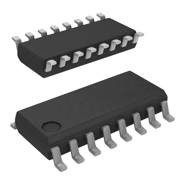
- Part No.:
- SL2309SI-1T
- Manufacturer:
- Skyworks Solutions Inc.
- Package:
- 16-SOIC (0.154", 3.90mm Width)
- Datasheet:
-
 SL2309SI-1T.pdf
- Description:
- IC BUFFER 140MHZ 9CH 3.3V 16SOIC
- Quantity:
- Payment:

- Shipping:

Inventory:2,252
Please send an inquiry. Send us your inquiry, and we will respond immediately.
Product details
Overview
SL2309SI-1T from Silicon Laboratories is a low-skew, low-jitter zero-delay buffer (ZDB) IC designed for high-speed clock distribution. It accepts one reference input clock (CLKIN) and delivers up to nine synchronized outputs (4+4+1), with 10–100 MHz operation at 3.3 V, 150 ps max output-to-output skew, and 140 ps max cycle-to-cycle jitter - deployed in industrial-grade digital copiers and network routers.
For engineers reviewing the SL2309SI-1T datasheet, SL2309SI-1T pinout, SL2309SI-1T application, or SL2309SI-1T equivalent, key selection criteria include its industrial temperature range (–40°C to +85°C), SOIC-16 package, PLL bypass mode (S2=1/S1=0), and compatibility with spread-spectrum clocking via SpreadThru™ architecture.
Technical Context
The SL2309SI-1T integrates an on-chip PLL that locks to CLKIN and uses internal feedback from CLKOUT to achieve zero input-to-output delay. Its dual-bank architecture (Bank A: CLKA1–CLKA4; Bank B: CLKB1–CLKB4) enables independent tri-state control via S1 and S2 pins, allowing dynamic power reduction by disabling unused banks.
In PLL bypass mode (S2=1, S1=0), the device operates as a non-zero-delay fanout buffer with DC-to-100 MHz support and disables input frequency detection. The -1 variant (standard drive) supports ≤100 MHz at 15 pF load and ≤66 MHz at 30 pF load, with 32 Ω typical output impedance and 26 mA max supply current at 66 MHz.
Key Specifications
| Parameter | Value and Actual Design Meaning |
|---|---|
| Operating Frequency | 10–100 MHz (standard drive, 15 pF load); supports DC input in bypass mode |
| Cycle-to-Cycle Jitter | 75–150 ps (66 MHz, 15 pF, standard drive) - directly impacts timing margin in synchronous systems |
| Output-to-Output Skew | ≤150 ps (all outputs equally loaded) - critical for parallel bus synchronization |
| Supply Voltage | 3.3 V ±10% - regulated internally to 1.8 V for stable PLL performance |
| Power Supply Current | 26 mA max at 66 MHz (all outputs active) - enables thermal management in dense PCB layouts |
| Temperature Range | –40°C to +85°C (industrial grade) - validated for embedded networking and office equipment |
| Package | 16-pin SOIC - compatible with standard reflow profiles and automated assembly |
Pinout & Package
SL2309SI-1T is housed in a 16-pin SOIC package (150-mil width), with exposed pad not present and RoHS-compliant finish. Pin layout supports standard PCB routing and decoupling capacitor placement adjacent to VDD pins (4 and 13).
| Pin/Terminal | Circuit Role | Design Meaning |
|---|---|---|
| 1 (CLKIN) | Reference clock input | Weak 250 kΩ pull-down; drives PLL and bypass path - must be terminated to avoid floating-induced shutdown |
| 2–3,14–15 (CLKA1–CLKA4) | Bank A clock outputs | Standard-drive outputs; tri-stated when S1=0/S2=0 - reduces jitter and power in partial-use configurations |
| 6–7,10–11 (CLKB1–CLKB4) | Bank B clock outputs | Identical drive strength to Bank A; independently controllable via S1/S2 - enables flexible clock domain partitioning |
| 4,13 (VDD) | 3.3 V power supply | Dual VDD pins reduce IR drop and improve noise immunity - requires 0.1 µF ceramic decoupling per pin |
| 5,12 (GND) | Power ground | Dual GND pins provide low-impedance return paths - essential for maintaining <150 ps skew across all outputs |
| 8 (S2), 9 (S1) | Mode select inputs | Weak 250 kΩ pull-up to VDD - define PLL enable, bypass, or full tri-state states per Table 2 in datasheet |
| 16 (CLKOUT) | PLL feedback output | Internally connected to PLL; external load matching Bank A/B determines zero-delay tuning - 2 pF inherent offset must be compensated |
Key Features
| Feature | Design Value |
|---|---|
| SpreadThru™ PLL architecture | Passes spread-spectrum modulation (SSCG) from CLKIN to all outputs without degradation - meets EMI compliance in DTV and PC platforms |
| Dual-bank output control | S1/S2 pins enable selective tri-state of Bank A, Bank B, or both - cuts dynamic power by >50% when only four clocks are needed |
| Input frequency detection | Shuts down PLL and forces all outputs to Hi-Z if CLKIN is DC or floating - draws <25 µA in power-down state |
| Zero-delay tuning | Adjustable via CLKOUT load vs. Bank A/B loads - enables fine-tuning of input-to-output phase alignment for DDR or PCI Express clock trees |
| Industrial-grade reliability | Specified for –40°C to +85°C with 400 ps max product-to-product skew - ensures timing consistency across production batches |
Applications
| Printers and MFPs | Digital Copiers |
|---|---|
Use Scenario: Synchronizing image sensor readout, print engine timing, and USB/Ethernet interface clocks in multi-function peripherals. IC Role / Device Role / Timing Role: Zero-delay buffer distributing a single master clock to multiple subsystems while maintaining sub-150 ps skew. Use Value: Eliminates inter-subsystem timing misalignment that causes image artifacts or data corruption during high-speed scanning/printing. |
Use Scenario: Coordinating document feeder, scanner, laser driver, and network controller clocks in industrial-grade digital copiers. IC Role / Device Role / Timing Role: Industrial-temperature clock distributor enabling deterministic real-time response across mechanical and digital domains. Use Value: Ensures consistent page throughput and avoids buffer underruns/overruns under thermal stress (-40°C to +85°C ambient). |
| PCs and Workstations | Routers and Switches |
Use Scenario: Driving memory controller, PCIe root complex, and SATA PHY clocks from a common 100 MHz reference in desktop motherboards. IC Role / Device Role / Timing Role: Low-jitter fanout buffer supporting simultaneous high-speed interfaces with shared clock domain. Use Value: Maintains <140 ps cycle-to-cycle jitter to meet PCIe Gen2 setup/hold requirements and prevent link training failures. |
Use Scenario: Distributing system clock to CPU, switch fabric ASIC, and multiple Gigabit Ethernet PHYs in Layer 3 enterprise routers. IC Role / Device Role / Timing Role: Clock repeater with PLL bypass capability for legacy backplane timing and SSCG-compatible front-panel interfaces. Use Value: Enables EMI reduction via spread-spectrum clocking on PHY links while preserving deterministic latency for control-plane processors. |
Equivalent & Alternatives
The following parts are listed as comparable options for similar zero-delay clock distribution applications.
| Alternative Part | Technical Difference | Application Difference | Selection Advice |
|---|---|---|---|
| SL23EP09 | Supports 10–220 MHz and 2.5–3.3 V operation; extended frequency range and wider voltage tolerance | Required for designs needing >100 MHz outputs or mixed-voltage systems (e.g., 2.5 V I/O domains) | Select SL23EP09 when upgrading from SL2309SI-1T for higher-frequency or lower-voltage clock trees. |
| ICS85310AGI-01LFT | 10-output LVDS zero-delay buffer; 3.3 V only; 1.2 GHz max input frequency but no SpreadThru™ SSC pass-through | Used in RF test equipment requiring differential signaling and ultra-low additive jitter (<50 ps) | Choose ICS85310AGI-01LFT only for LVDS-based systems where differential signaling and sub-100 ps jitter outweigh SSC compatibility needs. |
Compared with SL2309SI-1T, SL23EP09 extends operational frequency and voltage flexibility for next-gen designs, while ICS85310AGI-01LFT trades SSC support for LVDS outputs and tighter jitter - neither is pin-compatible, requiring layout revision and signal integrity revalidation.
Availability
SL2309SI-1T is available at Aetrix Electronics and suitable for industrial embedded systems, network infrastructure equipment, and office automation devices requiring stable component supply across extended temperature ranges and long production lifecycles.
Supply support for SL2309SI-1T includes scheduled delivery planning, volume procurement assistance, BOM continuity management, traceable sourcing, and lifecycle availability coordination for OEM customers, industrial embedded developers, connected-device designers, and electronics production programs.
Manufacturer
Silicon Laboratories Inc. is a U.S.-based semiconductor company specializing in timing, MCU, and wireless solutions, with design centers in Austin, TX and global manufacturing partnerships.
The SL2309 product line targets high-reliability clock distribution in cost-sensitive industrial and consumer electronics, emphasizing low power, low jitter, and flexible configuration for legacy and mixed-signal systems.
FAQ
What is the maximum operating frequency of SL2309SI-1T under standard drive conditions?
The SL2309SI-1T supports up to 100 MHz with a 15 pF load and up to 66 MHz with a 30 pF load under standard drive (-1) conditions at 3.3 V. These limits are defined in Table 1 of the datasheet and apply to both PLL-enabled and PLL-bypass modes. Exceeding these frequencies risks increased jitter and skew beyond specification.
Does SL2309SI-1T support spread-spectrum clocking (SSC)?
Yes, SL2309SI-1T implements SpreadThru™ technology that passes spread-spectrum modulation from CLKIN to all nine outputs without altering spread percentage, profile, or modulation frequency. This feature is active only when the PLL is enabled and is confirmed in the General Description section of the datasheet.
How does the S1 and S2 pin configuration affect SL2309SI-1T operation?
S1 (Pin 9) and S2 (Pin 8) control SL2309SI-1T's functional mode per Table 2: S2=0/S1=0 tri-states both banks; S2=0/S1=1 enables Bank A only; S2=1/S1=0 bypasses the PLL; S2=1/S1=1 enables full PLL operation. Both pins have internal 250 kΩ pull-ups, simplifying interface logic design.
What is the power consumption of SL2309SI-1T in shutdown mode?
In shutdown mode - triggered when CLKIN is DC or floating - SL2309SI-1T draws ≤25 µA (industrial grade) as specified in the DC Electrical Specifications table. This state forces all outputs to Hi-Z and disables the PLL, making it suitable for low-power standby in battery-backed systems.
Is SL2309SI-1T pin-compatible with other variants in the SL2309 family?
Yes, all SL2309 variants including SL2309SI-1T use identical 16-pin SOIC or TSSOP footprints and share the same pinout. However, drive strength (-1 vs. -1H), frequency limits, and temperature grading differ - substituting variants requires validation of load, frequency, and thermal requirements for the target application.
SL2309SI-1T Specifications
- Product attributes
- Attribute value
- Manufacturer:
- Skyworks Solutions Inc.
- Series:
- -
- Package/Case:
- 16-SOIC (0.154", 3.90mm Width)
- Packaging:
- Tape & Reel (TR)
- Product Status:
- Obsolete
- Programmable:
- Not Verified
- Type:
- -
- PLL:
- Yes with Bypass
- Input:
- Clock
- Output:
- LVCMOS
- Number of Circuits:
- 1
- Ratio - Input:Output:
- 1:9
- Differential - Input:Output:
- No/No
- Frequency - Max:
- 140MHz
- Divider/Multiplier:
- No/No
- Voltage - Supply:
- 3V ~ 3.6V
- Operating Temperature:
- -40°C ~ 85°C
- Mounting Type:
- Surface Mount
- Grade:
- -
- Qualification:
- -
- Supplier Device Package:
- 16-SOIC
SL2309SI-1T FAQ
1.How can I place an order for SL2309SI-1T through Aetrix?
Please submit a Request for Quotation (RFQ) for SL2309SI-1T on Aetrix. Our sales agent will provide a competitive quotation and guide you through the order confirmation once you accept the terms.
2.Are the price and stock information for SL2309SI-1T reliable?
The price and inventory of SL2309SI-1T are updated periodically and may fluctuate due to market conditions. Stock and pricing data are typically refreshed every 24 hours. Quotation validity for SL2309SI-1T is usually 5 days.
3.What payment methods are accepted for SL2309SI-1T?
We accept Wire Transfer, PayPal, Credit Card, Western Union, MoneyGram, and Escrow for SL2309SI-1T transactions.
Note: Certain payment methods may incur a processing fee.
4.How is shipping managed for SL2309SI-1T?
SL2309SI-1T orders can be shipped via leading logistics carriers, including DHL, UPS, FedEx, TNT, or Registered Mail.
Once your SL2309SI-1T order is processed, you will receive an email with the shipment details and tracking number.
Note: Tracking information may take up to 24 hours to appear. Express delivery typically takes 3–5 business days.
5.How can I obtain technical support or documentation for SL2309SI-1T?
For technical support, including SL2309SI-1T datasheets, pinout diagrams, or application guidance, please contact our engineering support team. They can provide detailed documentation and assistance for your SL2309SI-1T requirements.
6.How does Aetrix verify that SL2309SI-1T is sourced from the original manufacturer or authorized distributors?
All SL2309SI-1T products on Aetrix are procured from qualified distributors and authorized channels. Our dedicated quality assurance team conducts strict verification, including traceability checks and, if necessary, third-party testing. This ensures that SL2309SI-1T meets industry standards.
7.What is the process for return or replacement of SL2309SI-1T?
All SL2309SI-1T units undergo pre-shipment inspection (PSI). If there is an issue with SL2309SI-1T, returns or replacements are accepted under the following conditions:
1.Quantity discrepancies, incorrect items, or visible external defects (such as breakage or corrosion), acknowledged by Aetrix.
2.The issue is reported within 90 days of delivery.
3.The SL2309SI-1T part is unused and in its original packaging.
Return procedure for SL2309SI-1T:
1.Submit a request within 90 days.
2.Obtain a Return Material Authorization (RMA) from Aetrix.
SL2309SI-1T Tags

-
CD74HCT4046AM96
Texas Instruments

-
MC14046BDWR2G
onsemi

-
501MILFT
Renesas
-
CD74HC7046AM
Texas Instruments

-
CDCVF2505PWR
Texas Instruments

-
RC19004A100GNL#KB0
Renesas
-
SI5351A-B-GTR
Skyworks Solutions Inc.
-
CY2305SXI-1T
Infineon Technologies
-
570BILFT
Renesas

-
CDCE913PWR
Texas Instruments
-
CY2305SXI-1HT
Infineon Technologies

-
DS1086LU+T
Analog Devices Inc./Maxim Integrated
Tech Hub

Counterfeit components can hide behind convincing markings and passing basic function tests. This engineering reference covers source traceability, external inspection, X-ray, XRF, electrical testing, …

A practical engineering and sourcing framework covering lifecycle verification, lifetime-buy calculations, replacement qualification, supplier checks and counterfeit-risk controls.

TTL and CMOS logic families differ in thresholds, loading, output drive, power and timing. This engineering guide compares 74HC and 74HCT, calculates noise margins and checks 3.3 V/5 V compatibility.

A practical engineering guide to 3.3V and 5V logic compatibility, input thresholds, resistor dividers, translator ICs, MOSFET level shifting, I2C pull-ups, timing limits and power-sequencing risks.

The 74HC595 uses push-pull logic outputs, while the TPIC6B595 uses 50 V open-drain DMOS sinks for higher-power loads. This guide compares timing, current limits, 3.3 V interfacing, load wiring, thermal…

The 74HC595 converts serial data into eight stable parallel outputs. This guide covers pin functions, shift and storage timing, OE and MR behavior, drive-current limits, cascading, voltage compatibilit…

A technical comparison of level-sensitive latches and edge-triggered flip-flops, covering timing windows, setup and hold limits, master–slave operation, time borrowing, race-through, HDL inference and…

A D latch stores one bit while Enable controls when data can pass. This reference covers gate-level operation, truth tables, transparency, setup and hold timing, LE versus OE, common ICs and practical …

An SR latch stores one bit through cross-coupled feedback. This engineering reference covers NOR and NAND implementations, truth tables, forbidden-state recovery, gated operation, switch debouncing, fa…

Latch circuits retain one bit through feedback. This technical reference covers SR and D latches, truth tables, transparency, timing limits, latch-versus-flip-flop behavior, applications and common log…


