
 My Inquiry
 My Account


Texas Instruments SN65LV1224BRHBR
- Part No.:
- SN65LV1224BRHBR
- Manufacturer:
- Texas Instruments
- Category:
- Serializers, Deserializers
- Package:
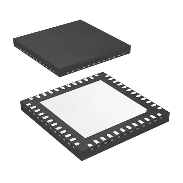
- 32-VFQFN Exposed Pad
- Datasheet:
-
 SN65LV1224BRHBR.pdf
- Description:
- IC SERIAL/DESERIAL 10:1 32-VQFN
- Quantity:
- Payment:

- Shipping:

Inventory:1,226
Please send an inquiry. Send us your inquiry, and we will respond immediately.
Product details
Overview
SN65LV1224BRHBR from Texas Instruments is a 10-bit LVDS deserializer IC designed for high-speed backplane and UTP interconnects. It recovers parallel data (10-bit LVTTL) from a 12-bit LVDS serial stream at 10–66 MHz system clock rates, delivering up to 660 Mbps payload bandwidth. Key confirmed parameters: 50 mV differential input threshold, ±100 ppm clock tolerance, 850×REFCLK-period PLL lock time from power-down, industrial −40°C to +85°C operation, and 5×5 mm QFN (RHB) package.
For engineers reviewing the SN65LV1224BRHBR datasheet, SN65LV1224BRHBR pinout, SN65LV1224BRHBR application, or SN65LV1224BRHBR equivalent, this page delivers verified electrical specs, functional timing behavior, fail-safe biasing details, and real-world synchronization mode trade-offs - all grounded in TI's SLLS621E revision December 2009 documentation.
Technical Context
The SN65LV1224BRHBR implements embedded-clock recovery using a PLL locked to the 12-bit serial frame (10 data + start/stop bits), with deterministic lock via SYNC patterns or random-data acquisition. Its dual-mode synchronization supports both rapid initialization (1026-cycle SYNC pattern) and hot-insertion into live backplanes.
It features on-chip fail-safe biasing that drives LOCK high and serial inputs inactive when unconnected, preventing false lock from noise. The deserializer outputs ROUT0–ROUT9 and RCLK only when LOCK is low, with RCLK edge polarity selectable via RCLK_R/F and output drive capability rated for ≤3 CMOS loads (15 pF total) at 66 MHz.
Key Specifications
| Parameter | Value and Actual Design Meaning |
|---|---|
| Function | 10-bit LVDS deserializer with embedded clock recovery and fail-safe input biasing |
| Data Rate Range | 120–792 Mbps serial (100–660 Mbps payload) at 10–66 MHz REFCLK |
| Differential Threshold | ±50 mV - enables higher noise margin but requires fail-safe circuitry to prevent false lock |
| PLL Lock Time | 850 × tRFCP from PWRDN (e.g., ~12.9 μs at 66 MHz); <2 μs from SYNC pattern |
| Supply Voltage | 3.0–3.6 V for both DVCC and AVCC - internally isolated rails support clean analog PLL operation |
| Operating Temp | −40°C to +85°C - qualified for industrial backplane and wireless infrastructure environments |
| Package | 28-pin QFN (5 mm × 5 mm, RHB) with exposed thermal pad - optimized for signal integrity and thermal dissipation |
Pinout & Package
SN65LV1224BRHBR uses a 28-pin QFN package (RHB) with 0.5 mm pitch and exposed thermal pad. Pin numbering follows TI's top-view convention (pin 1 marked by dot). Analog and digital supplies are separated (AVCC/DVCC) and grounds are partitioned (AGND/DGND) to minimize coupling between PLL and logic sections.
| Pin/Terminal | Circuit Role | Design Meaning |
|---|---|---|
| RI+, RI− | LVDS differential serial input | Accepts 12-bit framed LVDS stream; ±50 mV threshold with internal fail-safe bias |
| ROUT0–ROUT9 | LVTTL parallel data outputs | 10-bit recovered data; high-impedance when REN = low or LOCK = high |
| RCLK | LVTTL recovered clock output | Strobes ROUTx; edge polarity set by RCLK_R/F; valid only when LOCK = low |
| LOCK | Open-drain status indicator | Active-low signal confirms PLL lock to embedded clock; drives high during loss-of-lock |
| REFCLK | LVTTL reference clock input | 10–66 MHz local clock for PLL frequency reference; required for deterministic lock |
| PWRDN | Power-down control input | Low disables PLL and forces outputs to high-Z; exit requires reinitialization |
| REN | Output enable input | Low places ROUTx and RCLK in high-Z while preserving PLL lock state |
| AGND, DGND | Analog/digital ground terminals | Separate return paths prevent noise coupling between sensitive PLL and switching logic |
| AVCC, DVCC | Analog/digital supply terminals | Internally isolated 3.0–3.6 V rails; AVCC powers PLL, DVCC powers logic and I/O |
Key Features
| Feature | Design Value |
|---|---|
| Failsafe input biasing | On-chip circuitry pulls RI± and LOCK high when inputs float - prevents false lock during cable disconnect |
| Synchronization mode selection | Supports both deterministic SYNC-pattern lock (≤12.9 μs at 66 MHz) and open-loop random-data lock for hot insertion |
| Programmable RCLK edge | RCLK_R/F pin selects rising/falling edge strobe for ROUTx - enables timing alignment with downstream logic |
| High-noise-margin receiver | ±50 mV differential threshold improves immunity to crosstalk and EMI on backplanes and UTP cables |
| Low-power states | PWRDN reduces ICCR to ≤1 mA; REN maintains PLL lock while disabling outputs - ideal for burst-mode systems |
Applications
| Wireless Base Station Backhaul | DSLAM Line Card Interconnect |
|---|---|
|
Use Scenario: Transmitting 10-bit control/status data between FPGA-based radio processing units and remote RF modules over 1-meter UTP cables. IC Role / Device Role / Timing Role: Deserializes LVDS streams carrying CPRI-like framing; recovers clock and data without external PLL components. Use Value: Eliminates need for separate clock distribution; ±50 mV threshold tolerates >150 mV common-mode noise on outdoor cable runs. |
Use Scenario: Connecting line card ASICs to shelf controller across 3U backplane with 5 cm trace lengths and multiple vias. IC Role / Device Role / Timing Role: Converts high-speed serial links to parallel bus for register access; uses RCLK_R/F to align with controller setup/hold windows. Use Value: Flow-through pinout simplifies layer routing; 850×tRFCP lock time meets <15 μs resync requirement after hot-swap events. |
| Industrial Vision System Camera Link | Medical Imaging Data Aggregation |
|
Use Scenario: Receiving pixel data from high-resolution CMOS sensors over shielded twisted-pair cables in factory-floor cameras. IC Role / Device Role / Timing Role: Recovers 10-bit parallel video words synchronized to sensor pixel clock; LOCK signal feeds FPGA error-handling logic. Use Value: Fail-safe biasing prevents spurious frame errors during cable flexing; −40°C to +85°C rating ensures reliability in unconditioned enclosures. |
Use Scenario: Consolidating analog-to-digital converter outputs from multiple ultrasound transducer channels onto a central processing board. IC Role / Device Role / Timing Role: Deserializes time-aligned ADC samples from distributed front-end modules; REN enables per-channel power gating. Use Value: Low 1 mA power-down current extends system standby life; 15 pF load drive matches medical-grade FPGA I/O specs. |
Equivalent & Alternatives
The following parts are listed as comparable options for similar LVDS deserializer applications.
| Alternative Part | Technical Difference | Application Difference | Selection Advice |
|---|---|---|---|
| SN65LV1224BDB | Same die, 28-pin SSOP package (DB); 1.27 W max power vs. RHB's 2.85 W; no exposed thermal pad | Less suitable for high-density PCBs or thermally constrained enclosures; longer trace routing needed for flow-through layout | Choose DB for legacy SSOP footprints or cost-sensitive non-thermal designs; RHB preferred for new high-speed layouts. |
| DS92LV1224MTD | National Semiconductor (TI-acquired) pin-compatible variant; identical 10:1 deserialization, but lacks on-chip fail-safe biasing | Requires external bias resistors for floating-input robustness; lock time spec differs (no 850×tRFCP guarantee) | Select DS92LV1224MTD only if external biasing is acceptable and legacy design reuse is critical; SN65LV1224BRHBR offers superior noise immunity. |
Compared with SN65LV1224BDB and DS92LV1224MTD, SN65LV1224BRHBR delivers superior thermal performance via its QFN thermal pad, integrated fail-safe operation eliminating external components, and tighter lock-time specification - making it optimal for new industrial and telecom designs demanding reliability and layout efficiency.
Availability
SN65LV1224BRHBR is available at Aetrix Electronics and suitable for wireless base station backhaul, DSLAM line card interconnect, and industrial vision system applications requiring stable component supply across extended temperature ranges and long production lifecycles.
Supply support for SN65LV1224BRHBR includes scheduled delivery planning, volume procurement assistance, BOM continuity management, traceable sourcing, and lifecycle availability coordination for OEM customers, industrial embedded developers, connected-device designers, and electronics production programs.
Manufacturer
Texas Instruments is a global semiconductor leader specializing in analog, embedded processing, and connectivity technologies, with decades of expertise in high-speed interface solutions.
The SN65LV1224BRHBR belongs to TI's LVDS serializer/deserializer chipset family, engineered specifically for robust, low-jitter data transmission across noisy backplanes and unshielded cables in telecom and industrial infrastructure.
FAQ
What is the minimum and maximum REFCLK frequency supported by the SN65LV1224BRHBR?
The SN65LV1224BRHBR supports REFCLK frequencies from 10 MHz to 66 MHz, as specified in the recommended operating conditions. Operation outside this range is not guaranteed - below 10 MHz, PLL lock may fail; above 66 MHz, timing margins degrade and jitter increases beyond specification limits. The SN65LV1224BRHBR must receive a stable, low-jitter REFCLK within this band to maintain deterministic lock behavior and valid ROUTx output timing.
Does the SN65LV1224BRHBR require external components for PLL operation?
No, the SN65LV1224BRHBR requires no external components for PLL operation. Its PLL is fully integrated and self-contained, relying solely on the applied REFCLK signal and internal circuitry. This eliminates the need for external loop filters, capacitors, or inductors - reducing BOM count, board area, and tuning complexity. The SN65LV1224BRHBR achieves lock using only the REFCLK input and incoming LVDS data stream.
How does the fail-safe biasing function in the SN65LV1224BRHBR improve system reliability?
The SN65LV1224BRHBR's on-chip fail-safe circuit actively drives the RI+ and RI− inputs high and asserts LOCK high when the LVDS input is disconnected or floating. This prevents false lock caused by noise-induced transitions, ensuring the deserializer remains in a known, safe state. As a result, the SN65LV1224BRHBR avoids spurious data output or metastability during cable removal - critical for hot-pluggable telecom and industrial systems.
Can the SN65LV1224BRHBR synchronize to random data without SYNC patterns?
Yes, the SN65LV1224BRHBR supports random-data lock mode, enabling synchronization to arbitrary LVDS streams without transmitting dedicated SYNC patterns. In this mode, the deserializer detects data boundaries and locks to the embedded clock, supporting hot insertion into live backplanes. However, lock time becomes data-dependent and less deterministic than SYNC-pattern mode - the SN65LV1224BRHBR may take longer to achieve lock depending on input pattern characteristics.
What is the purpose of the RCLK_R/F pin on the SN65LV1224BRHBR?
The RCLK_R/F pin on the SN65LV1224BRHBR selects the active edge of the recovered RCLK output used to strobe the ROUT0–ROUT9 parallel data. When RCLK_R/F is high, RCLK rising edge latches data; when low, the falling edge is used. This flexibility allows precise timing alignment with downstream logic (e.g., FPGA registers), accommodating varying setup/hold requirements without external delay elements - a key feature of the SN65LV1224BRHBR's system-level integration.
SN65LV1224BRHBR Specifications
- Product attributes
- Attribute value
- Manufacturer:
- Texas Instruments
- Series:
- -
- Package/Case:
- 32-VFQFN Exposed Pad
- Packaging:
- Tape & Reel (TR)
- Product Status:
- Active
- Function:
- Deserializer
- Data Rate:
- 660Mbps
- Input Type:
- LVDS
- Output Type:
- LVTTL
- Number of Inputs:
- 1
- Number of Outputs:
- 10
- Voltage - Supply:
- 3V ~ 3.6V
- Operating Temperature:
- -40°C ~ 85°C (TA)
- Grade:
- -
- Qualification:
- -
- Mounting Type:
- Surface Mount
- Supplier Device Package:
- 32-VQFN (5x5)
SN65LV1224BRHBR FAQ
1.How can I place an order for SN65LV1224BRHBR through Aetrix?
Please submit a Request for Quotation (RFQ) for SN65LV1224BRHBR on Aetrix. Our sales agent will provide a competitive quotation and guide you through the order confirmation once you accept the terms.
2.Are the price and stock information for SN65LV1224BRHBR reliable?
The price and inventory of SN65LV1224BRHBR are updated periodically and may fluctuate due to market conditions. Stock and pricing data are typically refreshed every 24 hours. Quotation validity for SN65LV1224BRHBR is usually 5 days.
3.What payment methods are accepted for SN65LV1224BRHBR?
We accept Wire Transfer, PayPal, Credit Card, Western Union, MoneyGram, and Escrow for SN65LV1224BRHBR transactions.
Note: Certain payment methods may incur a processing fee.
4.How is shipping managed for SN65LV1224BRHBR?
SN65LV1224BRHBR orders can be shipped via leading logistics carriers, including DHL, UPS, FedEx, TNT, or Registered Mail.
Once your SN65LV1224BRHBR order is processed, you will receive an email with the shipment details and tracking number.
Note: Tracking information may take up to 24 hours to appear. Express delivery typically takes 3–5 business days.
5.How can I obtain technical support or documentation for SN65LV1224BRHBR?
For technical support, including SN65LV1224BRHBR datasheets, pinout diagrams, or application guidance, please contact our engineering support team. They can provide detailed documentation and assistance for your SN65LV1224BRHBR requirements.
6.How does Aetrix verify that SN65LV1224BRHBR is sourced from the original manufacturer or authorized distributors?
All SN65LV1224BRHBR products on Aetrix are procured from qualified distributors and authorized channels. Our dedicated quality assurance team conducts strict verification, including traceability checks and, if necessary, third-party testing. This ensures that SN65LV1224BRHBR meets industry standards.
7.What is the process for return or replacement of SN65LV1224BRHBR?
All SN65LV1224BRHBR units undergo pre-shipment inspection (PSI). If there is an issue with SN65LV1224BRHBR, returns or replacements are accepted under the following conditions:
1.Quantity discrepancies, incorrect items, or visible external defects (such as breakage or corrosion), acknowledged by Aetrix.
2.The issue is reported within 90 days of delivery.
3.The SN65LV1224BRHBR part is unused and in its original packaging.
Return procedure for SN65LV1224BRHBR:
1.Submit a request within 90 days.
2.Obtain a Return Material Authorization (RMA) from Aetrix.
SN65LV1224BRHBR Tags

-
SN65HVS880PWPR
Texas Instruments
-
SN65HVS882PWPR
Texas Instruments

-
FIN3386MTDX
onsemi
-
FIN3385MTDX
onsemi

-
SN65LV1023ARHBR
Texas Instruments
-
SN65LV1023ADBR
Texas Instruments
-
SN65LV1224BDBR
Texas Instruments

-
SN65LVDS93ADGGR
Texas Instruments
-
SN65LVDS93DGGR
Texas Instruments

-
TDES954RGZT
Texas Instruments
-
SN65LV1224BRHBT
Texas Instruments
-
DS90UB914QSQE/NOPB
Texas Instruments
Tech Hub

A practical engineering guide to 3.3V and 5V logic compatibility, input thresholds, resistor dividers, translator ICs, MOSFET level shifting, I2C pull-ups, timing limits and power-sequencing risks.

The 74HC595 uses push-pull logic outputs, while the TPIC6B595 uses 50 V open-drain DMOS sinks for higher-power loads. This guide compares timing, current limits, 3.3 V interfacing, load wiring, thermal…

The 74HC595 converts serial data into eight stable parallel outputs. This guide covers pin functions, shift and storage timing, OE and MR behavior, drive-current limits, cascading, voltage compatibilit…

A technical comparison of level-sensitive latches and edge-triggered flip-flops, covering timing windows, setup and hold limits, master–slave operation, time borrowing, race-through, HDL inference and…

A D latch stores one bit while Enable controls when data can pass. This reference covers gate-level operation, truth tables, transparency, setup and hold timing, LE versus OE, common ICs and practical …

An SR latch stores one bit through cross-coupled feedback. This engineering reference covers NOR and NAND implementations, truth tables, forbidden-state recovery, gated operation, switch debouncing, fa…

Latch circuits retain one bit through feedback. This technical reference covers SR and D latches, truth tables, transparency, timing limits, latch-versus-flip-flop behavior, applications and common log…

An engineering guide to LED driver operation, constant-current and constant-voltage outputs, linear and switching topologies, dimming, IC selection, calculations, replacement compatibility, and fault c…

Operational amplifier guide covering op amp basics, feedback, ideal vs real op amps, common configurations, buffer circuits, offset, bias current, gain-bandwidth, slew rate, rail-to-rail limits and sel…

Jumper cables guide covering safe connection order, red and black clamp placement, final ground connection, cable gauge, length, clamp quality, copper vs CCA cables, jump starter comparison and battery…


