
 My Inquiry
 My Account


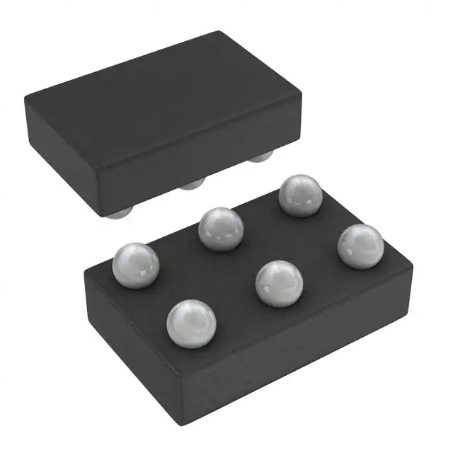
Texas Instruments SN74AUP1G97YEPR
- Part No.:
- SN74AUP1G97YEPR
- Manufacturer:
- Texas Instruments
- Package:
- 6-XFBGA, DSBGA
- Datasheet:
-
 SN74AUP1G97YEPR.pdf
- Description:
- IC GATE MULT-FUNC CONFIG 6-DSBGA
- Quantity:
- Payment:

- Shipping:

Inventory:1,125
Please send an inquiry. Send us your inquiry, and we will respond immediately.
Product details
Overview
SN74AUP1G97YEPR from Texas Instruments is a low-power configurable multiple-function logic gate in a 6-pin YFP (DSBGA) package. It implements eight logic functions-including MUX, AND, OR, NAND, NOR, inverter, and noninverter-via three input pins (A, B, C), with Schmitt-trigger inputs for noise immunity and slow-edge tolerance. Operates across 0.8 V to 3.6 V, delivers 5.6 ns max propagation delay at 3.3 V, and supports partial-power-down via Ioff.
For engineers reviewing the SN74AUP1G97YEPR datasheet, SN74AUP1G97YEPR pinout, SN74AUP1G97YEPR application, or SN74AUP1G97YEPR equivalent, this device is selected for ultra-low-power signal routing in battery-powered portable electronics, level-shifting interfaces, and point-to-point logic conditioning where supply voltage flexibility and input hysteresis are critical.
Technical Context
The SN74AUP1G97YEPR uses a single-gate architecture with three configurable inputs (A, B, C) and one output (Y), where function selection is determined by the 3-bit truth table. Its Schmitt-trigger inputs provide 0.79 V typical hysteresis at 3 V, enabling robust operation with slow-rising signals and high noise margin.
It features Ioff circuitry that disables outputs during partial power-down, preventing backflow current when VCC = 0 V. Input tolerance up to 3.6 V allows mixed-mode signaling with higher-voltage controllers while powered from sub-1 V rails.
Key Specifications
| Parameter | Value and Actual Design Meaning |
|---|---|
| VCC Range | 0.8 V to 3.6 V - enables direct interface with 0.9 V, 1.2 V, 1.8 V, 2.5 V, and 3.3 V logic domains without level shifters. |
| tpd Max | 5.6 ns at 3.3 V, CL = 5 pF - supports >100 MHz toggle rates in point-to-point configurations. |
| ICC Max | 0.9 mA at 3.6 V - ensures <1 µW static power at 0.8 V, extending battery life in always-on sensor nodes. |
| Input Hysteresis ΔVT | 0.79 V at VCC = 3 V - rejects noise spikes up to 26% of rail and accommodates RC-filtered or slow GPIO edges. |
| Ioff Leakage | 0.6 µA max at 0 V - blocks damaging current flow during hot-insertion or multi-rail sequencing. |
| CI Typ | 1.5 pF - minimizes capacitive loading on driving sources, preserving signal integrity in high-impedance paths. |
Pinout & Package
SN74AUP1G97YEPR is packaged in a 6-ball NanoStar™ DSBGA (YFP) with 0.5 mm max height, 0.23 mm solder bumps, and Pb-free SnAgCu finish. Pin 1 is identified by a solder-bump composition marker (● = Pb-free).
| Pin/Terminal | Circuit Role | Design Meaning |
|---|---|---|
| A | Data input 1 / Function select bit 0 | Primary logic input; used as data path in MUX mode or operand in AND/OR/NAND/NOR modes. |
| B | Data input 2 / Function select bit 1 | Secondary logic input; determines output state jointly with A and C per truth table. |
| C | Function select / Control input | Selects among eight logic functions; low = pass B, high = pass A in MUX configuration. |
| Y | Configurable logic output | Single-ended CMOS output capable of driving 4 mA at 3 V; compatible with 5 pF–30 pF loads. |
| VCC | Power supply | Supplies internal logic and output stage; must be decoupled locally due to low-impedance switching. |
| GND | Ground reference | Return path for all currents; requires low-inductance connection to minimize ground bounce. |
Key Features
| Feature | Design Value |
|---|---|
| Configurable logic function | Eight selectable functions (MUX, AND, OR, NAND, NOR, inverter, buffer) via 3-pin control-reduces BOM count and PCB footprint vs. discrete gates. |
| Schmitt-trigger inputs | 0.79 V hysteresis at 3 V enables reliable switching with slow or noisy signals, eliminating external RC filtering in sensor interfacing. |
| Ioff partial-power-down | 0.6 µA max leakage at 0 V VCC prevents back-current damage during power sequencing or hot-swap events. |
| 3.6-V I/O tolerant | Inputs accept up to 3.6 V regardless of VCC setting-supports mixed-voltage systems without external translators. |
| NanoStar™ DSBGA package | 0.5 mm max height, 1.02 mm × 1.52 mm body-enables ultra-thin wearable and IoT designs with minimal board area usage. |
Applications
| Wearable Sensor Hub | USB-C Power Delivery Controller Interface |
|---|---|
|
Use Scenario: Signal conditioning between ultra-low-power MEMS sensors (0.9 V IO) and a 1.8 V microcontroller. IC Role / Device Role / Timing Role: Configured as noninverting buffer to level-shift and clean slow-rising analog comparator outputs. Use Value: Eliminates need for discrete level shifter + Schmitt trigger; 1.5 pF input capacitance avoids loading sensitive sensor outputs. |
Use Scenario: Glue logic between USB-C PD controller (3.3 V) and system PMIC (1.2 V) for fault flag inversion and status multiplexing. IC Role / Device Role / Timing Role: Configured as inverter or 2-to-1 MUX to route overvoltage/overcurrent alerts based on port role negotiation. Use Value: 3.6-V tolerant inputs accept PD controller outputs directly; Ioff prevents backfeed during PMIC reset sequences. |
| Industrial Wireless Node | Medical Patch Monitor |
|
Use Scenario: Logic arbitration between BLE SoC wake-up signal and hardware watchdog timeout in a battery-operated edge node. IC Role / Device Role / Timing Role: Configured as OR gate to combine two independent reset sources into a single system reset line. Use Value: 0.9 mA max ICC at 3.6 V adds negligible load to coin-cell supply; Schmitt inputs reject EMI-induced glitches on long PCB traces. |
Use Scenario: Enabling/disabling analog front-end biasing based on electrode contact detection in a disposable ECG patch. IC Role / Device Role / Timing Role: Configured as AND gate with contact-detect input and MCU enable signal to gate power to op-amp stages. Use Value: 0.8 V minimum VCC allows operation directly from harvested energy storage; 0.23 mm bump pitch supports fine-pitch flex PCB assembly. |
Equivalent & Alternatives
The following parts are listed as comparable options for similar configurable logic gate applications.
| Alternative Part | Technical Difference | Application Difference | Selection Advice |
|---|---|---|---|
| SN74LVC1G97DBVR | Wider VCC range (1.65 V–5.5 V); no Schmitt inputs; higher ICC (10 µA typ); 5.5 ns tpd at 3.3 V. | Lacks hysteresis-requires external filtering for noisy environments; not suitable for sub-1 V operation. | Choose when interfacing with 5 V logic and Schmitt functionality is unnecessary. |
| SN74AUP1G57DBVR | Same AUP family; identical VCC range, Ioff, and Schmitt inputs; supports only 6 functions (no noninverter). | Missing noninverting buffer mode limits use in simple level-shift-only paths. | Choose when footprint compatibility is required and full 8-function set is not needed. |
Compared with SN74LVC1G97DBVR, SN74AUP1G97YEPR enables true sub-1 V operation and noise-immune sensing; compared with SN74AUP1G57DBVR, it adds the noninverting buffer function-critical for zero-delay signal pass-through in power-constrained medical monitors.
Availability
SN74AUP1G97YEPR is available at Aetrix Electronics and suitable for wearable sensor hubs, USB-C power delivery interfaces, industrial wireless nodes, and medical patch monitors requiring stable component supply across extended temperature ranges and long production lifecycles.
Supply support for SN74AUP1G97YEPR includes scheduled delivery planning, volume procurement assistance, BOM continuity management, traceable sourcing, and lifecycle availability coordination for OEM customers, industrial embedded developers, connected-device designers, and electronics production programs.
Manufacturer
Texas Instruments is a global semiconductor leader specializing in analog, embedded processing, and high-reliability ICs for industrial, automotive, and personal electronics markets.
The AUP (Advanced Ultra-Low-Power) product line delivers industry-leading static and dynamic power efficiency for battery-powered portable devices, with optimized performance from 0.8 V to 3.6 V.
FAQ
What logic functions does the SN74AUP1G97YEPR support?
The SN74AUP1G97YEPR supports eight configurable logic functions: 2-to-1 data selector (MUX), 2-input AND, 2-input OR with one inverted input, 2-input NAND with one inverted input, 2-input AND with one inverted input, 2-input NOR with one inverted input, 2-input OR, inverter, and noninverted buffer. These are selected using the three input pins A, B, and C according to the truth table in the datasheet. The SN74AUP1G97YEPR implements all functions within a single gate, eliminating the need for multiple discrete logic devices.
Does the SN74AUP1G97YEPR support partial power-down operation?
Yes, the SN74AUP1G97YEPR includes Ioff circuitry that disables outputs when VCC = 0 V, limiting off-state current to 0.6 µA max. This prevents damaging current backflow through the device during power sequencing or hot-swap events. The SN74AUP1G97YEPR maintains Ioff compliance across its full –40°C to 85°C operating range and is qualified for partial-power-down applications per JESD 78 Class II latch-up standards.
What is the significance of Schmitt-trigger inputs in the SN74AUP1G97YEPR?
The Schmitt-trigger inputs in the SN74AUP1G97YEPR provide hysteresis-0.79 V typical at 3 V-to reject noise and accommodate slow input transitions. This eliminates false triggering from EMI or RC-filtered signals, making the SN74AUP1G97YEPR ideal for interfacing with mechanical switches, analog comparators, or long PCB traces in industrial and medical applications without external debouncing components.
Can the SN74AUP1G97YEPR operate below 1 V?
Yes, the SN74AUP1G97YEPR is fully specified from 0.8 V to 3.6 V, including propagation delay, output drive strength, and Ioff behavior. At 0.8 V, it delivers 23.1 ns max tpd (CL = 5 pF) and 0.5 µA max ICC, enabling direct integration with sub-1 V processors and energy-harvesting systems. The SN74AUP1G97YEPR maintains functional correctness and timing predictability across the entire range without derating.
Which package type is used for the SN74AUP1G97YEPR?
The SN74AUP1G97YEPR uses the YFP package: a 6-ball NanoStar™ DSBGA with 0.23 mm solder bumps, 0.5 mm maximum height, and Pb-free SnAgCu finish. It measures 1.02 mm × 1.52 mm and complies with JEDEC MO-275. The SN74AUP1G97YEPR's pin 1 is identified by a Pb-free solder-bump marker (●), and the package supports reflow per IPC/JEDEC J-STD-020 Level-1 conditions.
SN74AUP1G97YEPR Specifications
- Product attributes
- Attribute value
- Manufacturer:
- Texas Instruments
- Series:
- 74AUP
- Package/Case:
- 6-XFBGA, DSBGA
- Packaging:
- Tape & Reel (TR)
- Product Status:
- Obsolete
- Logic Type:
- Configurable Multiple Function
- Number of Circuits:
- 1
- Number of Inputs:
- 3
- Schmitt Trigger Input:
- Yes
- Output Type:
- Single-Ended
- Current - Output High, Low:
- 4mA, 4mA
- Voltage - Supply:
- 0.8V ~ 3.6V
- Operating Temperature:
- -40°C ~ 85°C
- Grade:
- -
- Qualification:
- -
- Mounting Type:
- Surface Mount
- Supplier Device Package:
- 6-DSBGA
SN74AUP1G97YEPR FAQ
1.How can I place an order for SN74AUP1G97YEPR through Aetrix?
Please submit a Request for Quotation (RFQ) for SN74AUP1G97YEPR on Aetrix. Our sales agent will provide a competitive quotation and guide you through the order confirmation once you accept the terms.
2.Are the price and stock information for SN74AUP1G97YEPR reliable?
The price and inventory of SN74AUP1G97YEPR are updated periodically and may fluctuate due to market conditions. Stock and pricing data are typically refreshed every 24 hours. Quotation validity for SN74AUP1G97YEPR is usually 5 days.
3.What payment methods are accepted for SN74AUP1G97YEPR?
We accept Wire Transfer, PayPal, Credit Card, Western Union, MoneyGram, and Escrow for SN74AUP1G97YEPR transactions.
Note: Certain payment methods may incur a processing fee.
4.How is shipping managed for SN74AUP1G97YEPR?
SN74AUP1G97YEPR orders can be shipped via leading logistics carriers, including DHL, UPS, FedEx, TNT, or Registered Mail.
Once your SN74AUP1G97YEPR order is processed, you will receive an email with the shipment details and tracking number.
Note: Tracking information may take up to 24 hours to appear. Express delivery typically takes 3–5 business days.
5.How can I obtain technical support or documentation for SN74AUP1G97YEPR?
For technical support, including SN74AUP1G97YEPR datasheets, pinout diagrams, or application guidance, please contact our engineering support team. They can provide detailed documentation and assistance for your SN74AUP1G97YEPR requirements.
6.How does Aetrix verify that SN74AUP1G97YEPR is sourced from the original manufacturer or authorized distributors?
All SN74AUP1G97YEPR products on Aetrix are procured from qualified distributors and authorized channels. Our dedicated quality assurance team conducts strict verification, including traceability checks and, if necessary, third-party testing. This ensures that SN74AUP1G97YEPR meets industry standards.
7.What is the process for return or replacement of SN74AUP1G97YEPR?
All SN74AUP1G97YEPR units undergo pre-shipment inspection (PSI). If there is an issue with SN74AUP1G97YEPR, returns or replacements are accepted under the following conditions:
1.Quantity discrepancies, incorrect items, or visible external defects (such as breakage or corrosion), acknowledged by Aetrix.
2.The issue is reported within 90 days of delivery.
3.The SN74AUP1G97YEPR part is unused and in its original packaging.
Return procedure for SN74AUP1G97YEPR:
1.Submit a request within 90 days.
2.Obtain a Return Material Authorization (RMA) from Aetrix.
SN74AUP1G97YEPR Tags

-
SN74LVC1G97DCKR
Texas Instruments
-
SN74LVC1G97DRLR
Texas Instruments

-
SN74LVC1G97DBVR
Texas Instruments
-
NC7SZ57P6X
onsemi
-
SN74LVC1G97DCKT
Texas Instruments

-
MC100EP05DTR2G
onsemi
-
MC100EP08DTR2G
onsemi
-
NB7L86AMNHTBG
onsemi
-
HMC722LP3E
Analog Devices Inc.
-
74LVC1G97GW,125
Nexperia USA Inc.
-
74LVC1G57GW,125
Nexperia USA Inc.
-
74LVC1G97GV,125
Nexperia USA Inc.
Tech Hub

A practical engineering guide to 3.3V and 5V logic compatibility, input thresholds, resistor dividers, translator ICs, MOSFET level shifting, I2C pull-ups, timing limits and power-sequencing risks.

The 74HC595 uses push-pull logic outputs, while the TPIC6B595 uses 50 V open-drain DMOS sinks for higher-power loads. This guide compares timing, current limits, 3.3 V interfacing, load wiring, thermal…

The 74HC595 converts serial data into eight stable parallel outputs. This guide covers pin functions, shift and storage timing, OE and MR behavior, drive-current limits, cascading, voltage compatibilit…

A technical comparison of level-sensitive latches and edge-triggered flip-flops, covering timing windows, setup and hold limits, master–slave operation, time borrowing, race-through, HDL inference and…

A D latch stores one bit while Enable controls when data can pass. This reference covers gate-level operation, truth tables, transparency, setup and hold timing, LE versus OE, common ICs and practical …

An SR latch stores one bit through cross-coupled feedback. This engineering reference covers NOR and NAND implementations, truth tables, forbidden-state recovery, gated operation, switch debouncing, fa…

Latch circuits retain one bit through feedback. This technical reference covers SR and D latches, truth tables, transparency, timing limits, latch-versus-flip-flop behavior, applications and common log…

An engineering guide to LED driver operation, constant-current and constant-voltage outputs, linear and switching topologies, dimming, IC selection, calculations, replacement compatibility, and fault c…

Operational amplifier guide covering op amp basics, feedback, ideal vs real op amps, common configurations, buffer circuits, offset, bias current, gain-bandwidth, slew rate, rail-to-rail limits and sel…

Jumper cables guide covering safe connection order, red and black clamp placement, final ground connection, cable gauge, length, clamp quality, copper vs CCA cables, jump starter comparison and battery…


