
 My Inquiry
 My Account


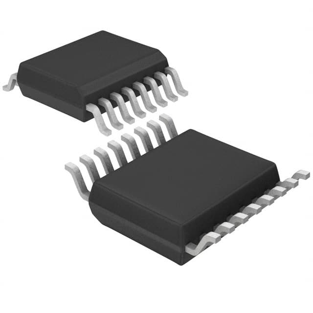
Texas Instruments SN74CBT3253DBQRG4
- Part No.:
- SN74CBT3253DBQRG4
- Manufacturer:
- Texas Instruments
- Category:
- Signal Switches, Multiplexers, Decoders
- Package:
- 16-SSOP (0.154", 3.90mm Width)
- Datasheet:
-
 SN74CBT3253DBQRG4.pdf
- Description:
- IC MUX/DEMUX 2 X 4:1 16SSOP
- Quantity:
- Payment:

- Shipping:

Inventory:4,062
Please send an inquiry. Send us your inquiry, and we will respond immediately.
Product details
Overview
SN74CBT3253DBQRG4 from Texas Instruments is a dual 1-of-4 high-speed FET multiplexer/demultiplexer with TTL-compatible inputs, 5 Ω typical on-state resistance at 4.5 V, <0.25 ns propagation delay (VCC = 5 V), and operation across −40°C to 85°C - used for bidirectional signal routing in bus-switching and level-translating applications within digital logic subsystems.
For engineers reviewing the SN74CBT3253DBQRG4 datasheet, SN74CBT3253DBQRG4 pinout, SN74CBT3253DBQRG4 application, or SN74CBT3253DBQRG4 equivalent, key selection criteria include on-resistance matching between channels, OE-controlled channel isolation, TTL-level control compatibility, and SSOP-16 thermal performance (θJA = 82°C/W).
Technical Context
This device integrates two independent 1:4 analog/digital switches sharing common select (S0/S1) and output-enable (1OE/2OE) controls. Each switch features low-capacitance FET architecture enabling bidirectional signal flow with minimal distortion and no DC bias requirement.
Control logic follows positive-true decoding: when both 1OE and 2OE are low, S1/S0 select one of four B-port terminals per A-port (1A→1B1–1B4, 2A→2B1–2B4); high OE disables the respective path. Input voltage range extends to −0.5 V to 7 V, supporting mixed-voltage domain interfacing.
Key Specifications
| Parameter | Value and Actual Design Meaning |
|---|---|
| Supply Voltage (VCC) | 4 V to 5.5 V - ensures compatibility with 5 V TTL and 4.5 V industrial rails without level-shifting circuitry. |
| On-State Resistance (ron) | 5 Ω typical (VCC = 4.5 V, VI = 0 V) - minimizes voltage drop and power loss during signal pass-through, critical for low-noise data paths. |
| Propagation Delay (tpd) | 0.25 ns max (VCC = 5 V, CL = 50 pF) - enables use in high-speed parallel buses up to ~1 GHz effective bandwidth. |
| Channel Isolation (Cio(OFF)) | 4 pF (OE = VCC) - reduces crosstalk between inactive channels in dense PCB layouts. |
| Input Capacitance (Ci) | 3.5 pF - limits loading on driving logic, preserving rise/fall times in fan-out-sensitive nodes. |
| Operating Temperature | −40°C to +85°C - validated for industrial-grade embedded systems and communications equipment. |
| ESD Rating | ±2 kV HBM - provides baseline robustness against handling-induced discharge without external protection. |
Pinout & Package
SN74CBT3253DBQRG4 is housed in a 16-pin SSOP (Shrink Small-Outline Package) with 0.65 mm lead pitch, 5.9 mm × 4.4 mm body size, and 1.75 mm maximum height - optimized for space-constrained industrial PCBs requiring moderate thermal dissipation (θJA = 82°C/W).
| Pin/Terminal | Circuit Role | Design Meaning |
|---|---|---|
| 1OE, 2OE | Output Enable (active-low) | Individually disables 1A/1B or 2A/2B switching paths; high state forces high-impedance isolation. |
| S0, S1 | Binary Select Inputs | Decode 1-of-4 channel selection for both A ports simultaneously (L/L → B1, L/H → B2, H/L → B3, H/H → B4). |
| 1A, 2A | Common Input/Output Terminals | Bidirectional signal ports - connect to shared bus or microcontroller data lines. |
| 1B1–1B4, 2B1–2B4 | Channel Output/Inputs | Four dedicated I/O terminals per A port; support multiplexed access to peripherals or memory banks. |
| VCC, GND | Power Supply | Single 5 V supply with decoupling required near pin 16 (VCC) and pin 8 (GND) to suppress switching noise. |
Key Features
| Feature | Design Value |
|---|---|
| TTL-Compatible Control Inputs | VIH = 2 V min, VIL = 0.8 V max - directly interfaces with legacy 5 V CMOS/TTL logic without pull-up resistors or translators. |
| Bidirectional Signal Routing | No inherent directionality - supports data flow from A-to-B or B-to-A with identical electrical characteristics. |
| Low On-Capacitance Switches | Cio(OFF) = 4 pF, Ci = 3.5 pF - preserves signal integrity in high-frequency digital buses and test equipment signal paths. |
| Break-Before-Make Operation | Guaranteed non-overlapping channel activation via S0/S1 sequencing - prevents short-circuits during reconfiguration. |
| High Channel Isolation | Typical off-isolation >60 dB at 10 MHz - suppresses interference between active and idle channels in multi-drop systems. |
Applications
| PCI Express Lane Multiplexing | Industrial I²C Bus Expansion |
|---|---|
Use Scenario: Dynamically rerouting PCIe Gen1/Gen2 lanes between two host controllers and multiple endpoint devices in modular compute platforms. IC Role / Device Role / Timing Role: Dual 1-of-4 analog switch providing low-latency, bidirectional lane selection with sub-nanosecond timing skew. Use Value: Enables hardware-reconfigurable topology without FPGA logic overhead or clock-domain crossing penalties. |
Use Scenario: Expanding a single microcontroller I²C bus to drive eight peripheral sensors across two isolated mechanical zones in factory automation PLCs. IC Role / Device Role / Timing Role: Level-agnostic bus switch isolating segments while maintaining SCL/SDA timing integrity under 400 kHz operation. Use Value: Eliminates need for discrete MOSFET-based bus extenders and reduces BOM count by consolidating dual-channel expansion. |
| Test Equipment Signal Path Switching | Legacy Microcontroller Port Sharing |
Use Scenario: Automated test systems routing calibrated reference signals between DUT interfaces and measurement instruments using relayless architecture. IC Role / Device Role / Timing Role: Low-Ron, low-Ci FET multiplexer ensuring minimal amplitude error (<0.5%) and phase shift (<1°) at 10 MHz. Use Value: Improves measurement repeatability and eliminates relay wear-out failure modes in high-cycle production testers. |
Use Scenario: Sharing limited GPIO pins on an 8-bit MCU between UART debug interface and SPI flash programming circuitry in field-deployable edge nodes. IC Role / Device Role / Timing Role: Bidirectional signal gate enabling time-multiplexed access to shared physical pins without software bit-banging delays. Use Value: Reduces PCB layer count by eliminating duplicate header connectors and simplifies firmware pin management logic. |
Equivalent & Alternatives
The following parts are listed as comparable options for similar dual 1-of-4 analog switch applications.
| Alternative Part | Technical Difference | Application Difference | Selection Advice |
|---|---|---|---|
| SN74CBT3253DBR | Same silicon die, identical electrical specs, SSOP-16 package with identical 0.65 mm pitch but different tape-and-reel packaging (2000 pcs/reel vs. 1000 pcs/reel for DBQRG4). | No functional difference; suitable for same PCB footprints and thermal environments. | Select SN74CBT3253DBR for higher-volume procurement where reel quantity aligns with SMT line planning. |
| SN74CBTD3253DBQR | Includes bus-hold circuitry on all I/Os (vs. none on SN74CBT3253DBQRG4), slightly higher ICC (10 μA vs. 3 μA), same ron/tpd. | Eliminates external pull-ups on floating bus lines but adds minor leakage current - preferred in systems with intermittent signal activity. | Choose SN74CBTD3253DBQR only if bus-hold functionality is explicitly required to prevent undefined states during power sequencing. |
Compared with SN74CBT3253DBQRG4, SN74CBT3253DBR offers identical performance in a functionally interchangeable package, while SN74CBTD3253DBQR trades zero bus-hold capability for enhanced input stability - making the original SN74CBT3253DBQRG4 optimal for low-power, high-speed deterministic routing where external biasing is already managed.
Availability
SN74CBT3253DBQRG4 is available at Aetrix Electronics and suitable for industrial automation, test instrumentation, and embedded communications systems requiring stable component supply, long-lifecycle support, and RoHS-compliant sourcing.
Supply support for SN74CBT3253DBQRG4 includes scheduled delivery planning, volume procurement assistance, BOM continuity management, traceable sourcing, and lifecycle availability coordination for OEM customers, industrial embedded developers, connected-device designers, and electronics production programs.
Manufacturer
Texas Instruments is a U.S.-based semiconductor company founded in 1930, specializing in analog and embedded processing technologies with global manufacturing, testing, and quality infrastructure.
The SN74CBT3253DBQRG4 belongs to TI's CBT (Crosspoint Bus Transceiver) family, engineered for high-speed, low-distortion signal routing in digital system interconnects - targeting applications where propagation delay, on-resistance matching, and channel isolation are design-critical.
FAQ
What is the maximum continuous current rating for each channel of the SN74CBT3253DBQRG4?
The SN74CBT3253DBQRG4 supports a continuous channel current of 128 mA per switch path. This rating applies under recommended operating conditions (VCC = 4 V to 5.5 V, TA = −40°C to 85°C) and assumes proper PCB thermal relief. Exceeding this current may increase on-resistance drift or accelerate electromigration in bond wires. Derating is advised above 70°C ambient.
Does the SN74CBT3253DBQRG4 support bidirectional signal flow without additional biasing?
Yes, the SN74CBT3253DBQRG4 supports fully bidirectional analog/digital signal routing between A and B ports without external DC bias or level-shifting components. Its FET-based architecture imposes no polarity constraints - signals propagate equally well from 1A to 1B1 or from 1B1 to 1A, provided VCC remains within 4 V–5.5 V and voltage differentials stay within −0.5 V to 7 V.
Can the SN74CBT3253DBQRG4 be used with 3.3 V logic control signals?
No - the SN74CBT3253DBQRG4 requires TTL-compatible control inputs: VIH must be ≥2 V and VIL ≤0.8 V. While 3.3 V outputs often exceed VIH, their VOL may rise above 0.8 V under load, risking incomplete turn-off. For reliable 3.3 V system integration, use a level translator such as the TXB0104 or ensure driver VOL ≤0.6 V at sink current.
What is the thermal resistance (θJA) of the SN74CBT3253DBQRG4 in its SSOP package?
The SN74CBT3253DBQRG4 in the DBQ package has a specified junction-to-ambient thermal resistance (θJA) of 90°C/W, measured per JESD 51-5. This value assumes standard JEDEC 2-layer board conditions (1-inch² copper pad, 2 oz Cu). Actual thermal performance improves with internal layer copper pours and thermal vias - typical board-level θJA ranges from 55°C/W to 70°C/W with optimized layout.
Is the SN74CBT3253DBQRG4 pin-compatible with other members of the SN74CBT3253 family?
Yes - all SN74CBT3253 variants (including D, DB, DBQ, PW, RGY packages) share identical 16-pin functional pinouts and logic behavior. The SN74CBT3253DBQRG4 matches the DBQ package pin map exactly: Pin 1 = 1OE, Pin 2 = S1, Pin 3 = 1B4, ..., Pin 16 = VCC. No PCB redesign is needed when migrating between DBQ-package versions.
SN74CBT3253DBQRG4 Specifications
- Product attributes
- Attribute value
- Manufacturer:
- Texas Instruments
- Series:
- 74CBT
- Package/Case:
- 16-SSOP (0.154", 3.90mm Width)
- Packaging:
- Tape & Reel (TR)
- Product Status:
- Obsolete
- Type:
- Multiplexer/Demultiplexer
- Circuit:
- 2 x 4:1
- Independent Circuits:
- 1
- Current - Output High, Low:
- -
- Voltage Supply Source:
- Single Supply
- Voltage - Supply:
- 4.5V ~ 5.5V
- Operating Temperature:
- -40°C ~ 85°C
- Grade:
- -
- Qualification:
- -
- Mounting Type:
- Surface Mount
- Supplier Device Package:
- 16-SSOP
SN74CBT3253DBQRG4 FAQ
1.How can I place an order for SN74CBT3253DBQRG4 through Aetrix?
Please submit a Request for Quotation (RFQ) for SN74CBT3253DBQRG4 on Aetrix. Our sales agent will provide a competitive quotation and guide you through the order confirmation once you accept the terms.
2.Are the price and stock information for SN74CBT3253DBQRG4 reliable?
The price and inventory of SN74CBT3253DBQRG4 are updated periodically and may fluctuate due to market conditions. Stock and pricing data are typically refreshed every 24 hours. Quotation validity for SN74CBT3253DBQRG4 is usually 5 days.
3.What payment methods are accepted for SN74CBT3253DBQRG4?
We accept Wire Transfer, PayPal, Credit Card, Western Union, MoneyGram, and Escrow for SN74CBT3253DBQRG4 transactions.
Note: Certain payment methods may incur a processing fee.
4.How is shipping managed for SN74CBT3253DBQRG4?
SN74CBT3253DBQRG4 orders can be shipped via leading logistics carriers, including DHL, UPS, FedEx, TNT, or Registered Mail.
Once your SN74CBT3253DBQRG4 order is processed, you will receive an email with the shipment details and tracking number.
Note: Tracking information may take up to 24 hours to appear. Express delivery typically takes 3–5 business days.
5.How can I obtain technical support or documentation for SN74CBT3253DBQRG4?
For technical support, including SN74CBT3253DBQRG4 datasheets, pinout diagrams, or application guidance, please contact our engineering support team. They can provide detailed documentation and assistance for your SN74CBT3253DBQRG4 requirements.
6.How does Aetrix verify that SN74CBT3253DBQRG4 is sourced from the original manufacturer or authorized distributors?
All SN74CBT3253DBQRG4 products on Aetrix are procured from qualified distributors and authorized channels. Our dedicated quality assurance team conducts strict verification, including traceability checks and, if necessary, third-party testing. This ensures that SN74CBT3253DBQRG4 meets industry standards.
7.What is the process for return or replacement of SN74CBT3253DBQRG4?
All SN74CBT3253DBQRG4 units undergo pre-shipment inspection (PSI). If there is an issue with SN74CBT3253DBQRG4, returns or replacements are accepted under the following conditions:
1.Quantity discrepancies, incorrect items, or visible external defects (such as breakage or corrosion), acknowledged by Aetrix.
2.The issue is reported within 90 days of delivery.
3.The SN74CBT3253DBQRG4 part is unused and in its original packaging.
Return procedure for SN74CBT3253DBQRG4:
1.Submit a request within 90 days.
2.Obtain a Return Material Authorization (RMA) from Aetrix.
SN74CBT3253DBQRG4 Tags

-
SN74HC138DR
Texas Instruments
-
TC7SB3157CFU,LF(CT
Toshiba Semiconductor and Storage
-
74CBTLV3257PW,118
Nexperia USA Inc.

-
SN74CBTLV3257PWR
Texas Instruments
-
74CBTLV3257GUX
Nexperia USA Inc.
-
74HC154BQ,118
Nexperia USA Inc.

-
P3S0200GMX
NXP USA Inc.

-
SN74CB3Q3245PWR
Texas Instruments
-
SN74CB3Q3257RGYR
Texas Instruments

-
TCA9543APWR
Texas Instruments
-
TCA9546APWR
Texas Instruments

-
SN74HC138N
Texas Instruments
Tech Hub

A practical engineering guide to 3.3V and 5V logic compatibility, input thresholds, resistor dividers, translator ICs, MOSFET level shifting, I2C pull-ups, timing limits and power-sequencing risks.

The 74HC595 uses push-pull logic outputs, while the TPIC6B595 uses 50 V open-drain DMOS sinks for higher-power loads. This guide compares timing, current limits, 3.3 V interfacing, load wiring, thermal…

The 74HC595 converts serial data into eight stable parallel outputs. This guide covers pin functions, shift and storage timing, OE and MR behavior, drive-current limits, cascading, voltage compatibilit…

A technical comparison of level-sensitive latches and edge-triggered flip-flops, covering timing windows, setup and hold limits, master–slave operation, time borrowing, race-through, HDL inference and…

A D latch stores one bit while Enable controls when data can pass. This reference covers gate-level operation, truth tables, transparency, setup and hold timing, LE versus OE, common ICs and practical …

An SR latch stores one bit through cross-coupled feedback. This engineering reference covers NOR and NAND implementations, truth tables, forbidden-state recovery, gated operation, switch debouncing, fa…

Latch circuits retain one bit through feedback. This technical reference covers SR and D latches, truth tables, transparency, timing limits, latch-versus-flip-flop behavior, applications and common log…

An engineering guide to LED driver operation, constant-current and constant-voltage outputs, linear and switching topologies, dimming, IC selection, calculations, replacement compatibility, and fault c…

Operational amplifier guide covering op amp basics, feedback, ideal vs real op amps, common configurations, buffer circuits, offset, bias current, gain-bandwidth, slew rate, rail-to-rail limits and sel…

Jumper cables guide covering safe connection order, red and black clamp placement, final ground connection, cable gauge, length, clamp quality, copper vs CCA cables, jump starter comparison and battery…


