
 My Inquiry
 My Account


Texas Instruments SN74V263-15GGM
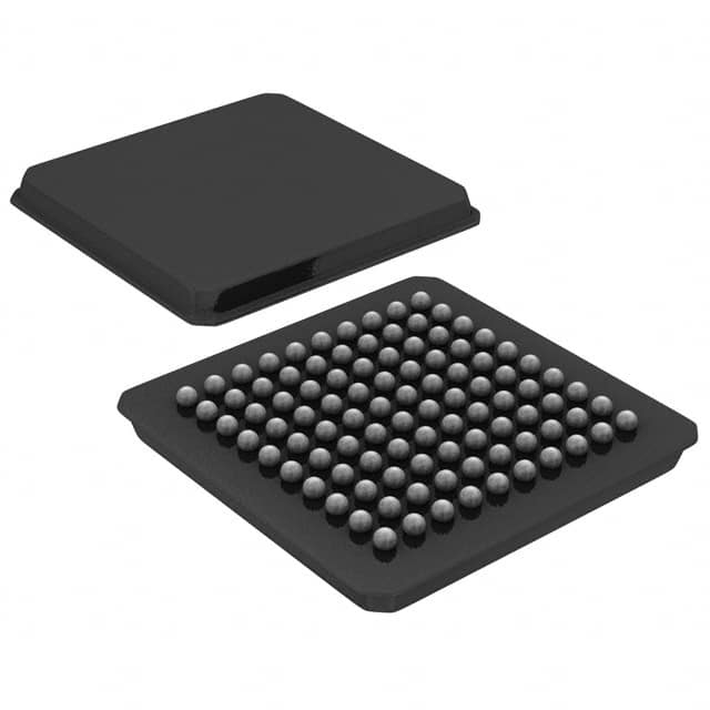
- Part No.:
- SN74V263-15GGM
- Manufacturer:
- Texas Instruments
- Category:
- FIFOs Memory
- Package:
- 100-LFBGA
- Datasheet:
-
 SN74V263-15GGM.pdf
- Description:
- IC FIFO SYNC 16KX9 10NS 100BGA
- Quantity:
- Payment:

- Shipping:

Inventory:2,689
Please send an inquiry. Send us your inquiry, and we will respond immediately.
Product details
Overview
SN74V263-15GGM from Texas Instruments is a 3.3-V CMOS first-in, first-out (FIFO) memory with 8192 × 18 or 16384 × 9 configurable depth/width, 166-MHz operation, 6-ns read/write cycle time, and user-selectable ×9/×18 bus sizing - deployed in high-speed data buffering for DSP interfacing and telecom line cards.
For engineers reviewing the SN74V263-15GGM datasheet, SN74V263-15GGM pinout, SN74V263-15GGM application, or SN74V263-15GGM equivalent, key selection criteria include FWFT vs. standard timing mode, programmable almost-empty/full flag offsets, independent RCLK/WCLK domains, big/little-endian byte ordering, and zero-latency retransmit capability.
Technical Context
This FIFO implements dual-clock asynchronous operation with fully independent read and write clock domains (RCLK/WCLK), supporting 0–166 MHz frequencies without inter-clock dependency. It integrates a flexible ×9/×18 bus-matching architecture controlled by IW/OW pins during master reset, enabling dynamic port width configuration.
The device features two selectable timing modes: First-Word Fall-Through (FWFT), where the first written word appears on Qn after three RCLK edges without REN assertion; and standard mode, requiring explicit REN + RCLK for all reads including the first word. Retransmit functionality supports zero-latency mode via RM pin configuration.
Key Specifications
| Parameter | Value and Actual Design Meaning |
|---|---|
| Memory Depth × Width | 8192 × 18 or 16384 × 9 - enables flexible data buffering for mismatched bus interfaces. |
| Max Clock Frequency | 166 MHz - supports high-throughput streaming in DSP and network applications. |
| Read/Write Cycle Time | 6 ns - guarantees deterministic latency for real-time data handoff between subsystems. |
| Bus Configuration | User-selectable ×9/×18 input/output via IW/OW pins - eliminates glue logic in heterogeneous system interconnects. |
| Timing Mode | FWFT or standard mode selected by FWFT/SI at master reset - determines first-word access behavior and flag semantics (OR/IR vs. EF/FF). |
| Retransmit Latency | Zero-latency or normal-latency mode set by RM pin - allows immediate reread of FIFO head without pipeline delay. |
| Flag Programmability | PAE/PAF offsets programmable serially or in parallel - supports precise buffer watermarking for flow control. |
Pinout & Package
SN74V263-15GGM is housed in a 100-pin Ball Grid Array (BGA) package designated GGM per TI SCAS669D datasheet. Pin functions are validated per official top-view pinout diagram and terminal description table.
| Pin/Terminal | Circuit Role | Design Meaning |
|---|---|---|
| MRS | Master Reset Input | Asynchronous initialization of read/write pointers, flags, and configuration registers; required before first write. |
| WCLK / RCLK | Independent Clock Inputs | Enable concurrent read/write operations at up to 166 MHz; no frequency or phase relationship required. |
| WEN / REN | Write/Read Enable Controls | Gate data transfer on respective clock edges; ignored when FIFO is full/empty. |
| OE | Output Enable | Places Q0–Q17 outputs in high-impedance state - supports shared bus architectures. |
| IW / OW | Input/Output Width Select | Configure ×9 or ×18 port widths during master reset - enables seamless bus-width translation. |
| BE | Big/Little Endian Select | Determines MSB/LSB order when converting between ×18 and ×9 formats - critical for data integrity in mixed-width transfers. |
| RT | Retransmit Trigger | On rising RCLK edge with RT low, resets read pointer to start address - enables repeat playback without host intervention. |
| PAE / PAF | Programmable Flags | Assert based on user-defined word counts - used for autonomous flow control in streaming pipelines. |
Key Features
| Feature | Design Value |
|---|---|
| Flexible Bus Matching | ×9/×18 input and output ports independently configurable - eliminates external multiplexers in DSP-to-peripheral bridging. |
| Zero-Latency Retransmit | First retransmitted word appears on Qn synchronized to same RCLK edge that asserts RT - enables glitch-free replay in video/audio buffers. |
| First-Word Fall-Through Mode | Initial data appears on outputs after three RCLK edges without REN - reduces latency in real-time capture paths. |
| Programmable Flag Offsets | PAE/PAF thresholds set via serial or parallel loading - supports adaptive backpressure signaling in variable-rate systems. |
| 5-V-Tolerant Inputs | All control and data inputs accept 5-V logic levels - simplifies interface with legacy 5-V controllers without level shifters. |
Applications
| Telecom Line Card Buffering | DSP External Memory Interface |
|---|---|
Use Scenario: Buffering high-speed TDM or packetized voice/data streams between framer ICs and line drivers in access equipment. IC Role / Device Role / Timing Role: Asynchronous FIFO decoupling clock domains between OC-3/STM-1 framer (125 MHz) and slower line driver (25 MHz). Use Value: Prevents data loss during clock domain crossing while supporting 166-MHz burst writes and sustained 62.5-MHz reads. | Use Scenario: Interfacing TI C6x DSPs via EMIF or XBus to offload real-time signal processing tasks requiring large intermediate data storage. IC Role / Device Role / Timing Role: High-bandwidth data staging buffer between DSP's external memory controller and custom peripherals or ADC/DAC chains. Use Value: Enables glueless connection per TI SPRA534/SPRA547 app notes; supports FWFT mode for minimal latency on first sample retrieval. |
| Video Frame Synchronization | Industrial Protocol Gateway |
Use Scenario: Aligning asynchronous video streams from multiple cameras operating at different frame rates before encoding. IC Role / Device Role / Timing Role: Dual-clock FIFO absorbing jitter and rate mismatches between camera sensor interfaces (MIPI CSI-2 bridge) and encoder ASIC clocks. Use Value: 8192 × 18 capacity holds >1.5 lines of 1080p YUV422 data; zero-latency retransmit supports frame retransmission on error detection. | Use Scenario: Bridging Modbus RTU (RS-485) and Ethernet/IP networks in factory automation controllers requiring protocol translation and buffering. IC Role / Device Role / Timing Role: Data staging element isolating slow serial protocol stack from high-speed Ethernet MAC layer. Use Value: Independent RCLK/WCLK domains allow simultaneous 115.2-kbps serial receive and 100-Mbps Ethernet transmit; PAE/PAF flags trigger DMA transfers at optimal fill levels. |
Equivalent & Alternatives
The following parts are listed as comparable options for similar FIFO memory applications.
| Alternative Part | Technical Difference | Application Difference | Selection Advice |
|---|---|---|---|
| IDT72V263 | Same 8192 × 18 organization, but rated for 133 MHz max; lacks zero-latency retransmit and FWFT mode. | Suitable for lower-speed legacy systems where first-word latency is not critical. | Select IDT72V263 only if 133-MHz operation suffices and FWFT/zero-latency features are unused. |
| SN74V265 | Pin-compatible upgrade with 166-MHz speed, identical pinout and feature set - adds JTAG boundary-scan support. | Drop-in replacement where enhanced testability and long-term availability are priorities. | Prefer SN74V265 for new designs requiring production test coverage and extended lifecycle support. |
Compared with IDT72V263, SN74V263-15GGM delivers 25% higher bandwidth and deterministic first-word latency; versus SN74V265, it offers identical core functionality at lower cost where JTAG is unnecessary.
Availability
SN74V263-15GGM is available at Aetrix Electronics and suitable for telecom infrastructure, DSP-based signal processing, and industrial protocol gateway applications requiring stable component supply across multi-year production cycles.
Supply support for SN74V263-15GGM includes scheduled delivery planning, volume procurement assistance, BOM continuity management, traceable sourcing, and lifecycle availability coordination for OEM customers, industrial embedded developers, connected-device designers, and electronics production programs.
Manufacturer
Texas Instruments is a global semiconductor leader specializing in analog, embedded processing, and logic solutions, with decades of experience in high-speed interface and memory products.
The SN74V263-15GGM belongs to TI's high-speed FIFO family designed specifically for clock-domain isolation and data rate matching in DSP, telecom, and video systems - emphasizing low-latency, configurability, and robust flag signaling.
FAQ
What memory organization does SN74V263-15GGM support?
SN74V263-15GGM supports two memory configurations: 8192 × 18 (147,456 bits) or 16384 × 9 (147,456 bits), selected via IW and OW pin states during master reset. Both configurations deliver identical total bit capacity but differ in data path width - enabling optimization for either wide-bus throughput or narrow-bus compatibility.
Does SN74V263-15GGM support 5-V logic inputs?
Yes, SN74V263-15GGM features 5-V-tolerant inputs on all control and data pins (D0–D17, WEN, REN, MRS, etc.), allowing direct interfacing with 5-V microcontrollers or FPGAs without external level-shifting circuitry - a key advantage in mixed-voltage system designs.
How does the FWFT mode affect first-word latency in SN74V263-15GGM?
In FWFT mode, the first word written to an empty SN74V263-15GGM appears on Q0–Q17 outputs after exactly three RCLK rising edges - with no REN assertion required. This fixed, low-latency path is essential for real-time capture applications where minimizing initial data access delay is critical.
Can SN74V263-15GGM be used in systems with asynchronous read and write clocks?
Yes, SN74V263-15GGM explicitly supports fully asynchronous operation: RCLK and WCLK may run at any frequency from 0 to 166 MHz, with no phase, frequency, or duty-cycle constraints between them. This makes SN74V263-15GGM ideal for bridging disparate clock domains in complex SoC or FPGA-based systems.
What is the purpose of the RM pin on SN74V263-15GGM?
The RM (Retransmit Latency Mode) pin configures SN74V263-15GGM's retransmit behavior during master reset: a low level selects zero-latency mode, where the first retransmitted word appears on Qn synchronized to the same RCLK edge that triggers RT; a high level selects normal-latency mode with one-cycle delay.
SN74V263-15GGM Specifications
- Product attributes
- Attribute value
- Manufacturer:
- Texas Instruments
- Series:
- 74V
- Package/Case:
- 100-LFBGA
- Packaging:
- Tray
- Product Status:
- Obsolete
- Programmable:
- Not Verified
- Memory Size:
- 144K (8K x 18)(16K x 9)
- Function:
- Synchronous
- Data Rate:
- 66.7MHz
- Access Time:
- 10ns
- Voltage - Supply:
- 3.15 V ~ 3.45 V
- Current - Supply (Max):
- 35mA
- Bus Directional:
- Uni-Directional
- Expansion Type:
- Depth, Width
- Programmable Flags Support:
- Yes
- Retransmit Capability:
- Yes
- FWFT Support:
- Yes
- Operating Temperature:
- 0°C ~ 70°C
- Mounting Type:
- Surface Mount
- Supplier Device Package:
- 100-BGA MICROSTAR (10x10)
SN74V263-15GGM FAQ
1.How can I place an order for SN74V263-15GGM through Aetrix?
Please submit a Request for Quotation (RFQ) for SN74V263-15GGM on Aetrix. Our sales agent will provide a competitive quotation and guide you through the order confirmation once you accept the terms.
2.Are the price and stock information for SN74V263-15GGM reliable?
The price and inventory of SN74V263-15GGM are updated periodically and may fluctuate due to market conditions. Stock and pricing data are typically refreshed every 24 hours. Quotation validity for SN74V263-15GGM is usually 5 days.
3.What payment methods are accepted for SN74V263-15GGM?
We accept Wire Transfer, PayPal, Credit Card, Western Union, MoneyGram, and Escrow for SN74V263-15GGM transactions.
Note: Certain payment methods may incur a processing fee.
4.How is shipping managed for SN74V263-15GGM?
SN74V263-15GGM orders can be shipped via leading logistics carriers, including DHL, UPS, FedEx, TNT, or Registered Mail.
Once your SN74V263-15GGM order is processed, you will receive an email with the shipment details and tracking number.
Note: Tracking information may take up to 24 hours to appear. Express delivery typically takes 3–5 business days.
5.How can I obtain technical support or documentation for SN74V263-15GGM?
For technical support, including SN74V263-15GGM datasheets, pinout diagrams, or application guidance, please contact our engineering support team. They can provide detailed documentation and assistance for your SN74V263-15GGM requirements.
6.How does Aetrix verify that SN74V263-15GGM is sourced from the original manufacturer or authorized distributors?
All SN74V263-15GGM products on Aetrix are procured from qualified distributors and authorized channels. Our dedicated quality assurance team conducts strict verification, including traceability checks and, if necessary, third-party testing. This ensures that SN74V263-15GGM meets industry standards.
7.What is the process for return or replacement of SN74V263-15GGM?
All SN74V263-15GGM units undergo pre-shipment inspection (PSI). If there is an issue with SN74V263-15GGM, returns or replacements are accepted under the following conditions:
1.Quantity discrepancies, incorrect items, or visible external defects (such as breakage or corrosion), acknowledged by Aetrix.
2.The issue is reported within 90 days of delivery.
3.The SN74V263-15GGM part is unused and in its original packaging.
Return procedure for SN74V263-15GGM:
1.Submit a request within 90 days.
2.Obtain a Return Material Authorization (RMA) from Aetrix.
SN74V263-15GGM Tags
-
7201LA15JGI
Renesas
-
7204L12JG
Renesas

-
72V82L15PAG8
Renesas

-
7205L15JGI
Renesas
-
7208L20JG
Renesas

-
72V2105L10PFG
Renesas
-
72V2111L15PFGI
Renesas

-
72V2113L6PFG
Renesas
-
72V36110L6PFG
Renesas

-
SN74ALVC7804-40DL
Texas Instruments
-
7202LA25JGI
Renesas
-
SN74V245-15PAG
Texas Instruments
Tech Hub

A practical engineering guide to 3.3V and 5V logic compatibility, input thresholds, resistor dividers, translator ICs, MOSFET level shifting, I2C pull-ups, timing limits and power-sequencing risks.

The 74HC595 uses push-pull logic outputs, while the TPIC6B595 uses 50 V open-drain DMOS sinks for higher-power loads. This guide compares timing, current limits, 3.3 V interfacing, load wiring, thermal…

The 74HC595 converts serial data into eight stable parallel outputs. This guide covers pin functions, shift and storage timing, OE and MR behavior, drive-current limits, cascading, voltage compatibilit…

A technical comparison of level-sensitive latches and edge-triggered flip-flops, covering timing windows, setup and hold limits, master–slave operation, time borrowing, race-through, HDL inference and…

A D latch stores one bit while Enable controls when data can pass. This reference covers gate-level operation, truth tables, transparency, setup and hold timing, LE versus OE, common ICs and practical …

An SR latch stores one bit through cross-coupled feedback. This engineering reference covers NOR and NAND implementations, truth tables, forbidden-state recovery, gated operation, switch debouncing, fa…

Latch circuits retain one bit through feedback. This technical reference covers SR and D latches, truth tables, transparency, timing limits, latch-versus-flip-flop behavior, applications and common log…

An engineering guide to LED driver operation, constant-current and constant-voltage outputs, linear and switching topologies, dimming, IC selection, calculations, replacement compatibility, and fault c…

Operational amplifier guide covering op amp basics, feedback, ideal vs real op amps, common configurations, buffer circuits, offset, bias current, gain-bandwidth, slew rate, rail-to-rail limits and sel…

Jumper cables guide covering safe connection order, red and black clamp placement, final ground connection, cable gauge, length, clamp quality, copper vs CCA cables, jump starter comparison and battery…


