
 My Inquiry
 My Account


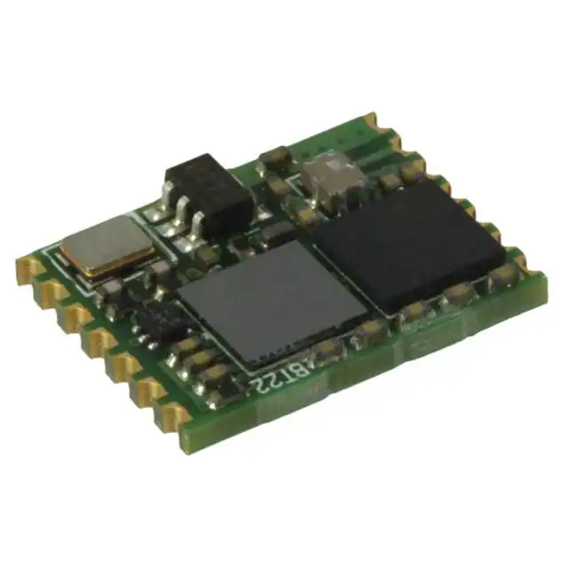
STMicroelectronics SPBT2532C2.AT
- Part No.:
- SPBT2532C2.AT
- Manufacturer:
- STMicroelectronics
- Category:
- RF Transceiver Modules and Modems
- Package:
- PCB Module
- Datasheet:
-
 SPBT2532C2.AT.pdf
- Description:
- RF TXRX MODULE BLUETOOTH SMD
- Quantity:
- Payment:

- Shipping:

Inventory:1,236
Please send an inquiry. Send us your inquiry, and we will respond immediately.
Product details
Overview
SPBT2532C2.AT from STMicroelectronics is a Bluetooth® 2.1 class-2 module integrating baseband, RF, antenna, Flash (256 KB), RAM (48 KB), and embedded AT firmware for Serial Port Profile (SPP). It delivers up to +2 dBm output power, supports EDR at 2 Mbps, and operates from a single 3.3 V supply with no external oscillator required. It is used in industrial serial cable replacement and sensor monitoring systems.
For engineers reviewing the SPBT2532C2.AT datasheet, SPBT2532C2.AT pinout, SPBT2532C2.AT application, or SPBT2532C2.AT equivalent, key selection factors include UART interface speed (up to 3.25 Mbit/s), integrated SPP firmware, class-2 RF output compliance, low-power deep-sleep mode (3.1 mA), and 4 GPIOs configurable via AT commands.
Technical Context
The module implements the full Bluetooth 2.1 stack-including LMP, L2CAP, RFCOMM, and SPP-within its embedded firmware. Its baseband processor runs at 32 MHz (or 16/8 MHz for reduced power), and RF performance is derived from the STLC2500D transceiver IC, supporting adaptive frequency hopping (AFH) and WLAN coexistence.
Communication is handled exclusively via a high-speed UART (default AT command interface), with all I/O pins 5 V tolerant except ADC inputs. The module requires no external clock source and uses an internal RC oscillator calibrated against the Bluetooth reference frequency.
Key Specifications
| Parameter | Value and Actual Design Meaning |
|---|---|
| Bluetooth Version | Compliant with Bluetooth specification v2.1 + EDR - enables 2 Mbps data rate and improved link robustness over v2.0. |
| Output Power Class | Class-2 (max +2 dBm) - supports up to 10 m range in typical indoor environments without regulatory re-certification. |
| UART Speed | Up to 3.25 Mbit/s - allows high-throughput transparent serial bridging with minimal latency for real-time control. |
| Memory | 256 KB Flash / 48 KB RAM - sufficient for dual-role SPP firmware, user AT configuration storage, and runtime stack execution. |
| Supply Voltage | 2.8–3.6 V (typ. 3.0 V) - compatible with standard 3.3 V logic rails and LDO-regulated embedded power domains. |
| Deep-Sleep Current | 3.1 mA during page/inquiry scan - enables battery-powered operation for months in periodic polling applications. |
| Operating Temp | –40 °C to +85 °C (at 8 MHz CPU) - suitable for industrial control cabinets and outdoor sensor enclosures. |
Pinout & Package
Package: 10.5 × 13.5 mm surface-mount module with castellated edge pads (16-pin layout, 1.0 mm pitch).
| Pin/Terminal | Circuit Role | Design Meaning |
|---|---|---|
| 1 (ADC) | Analog input | Non-5V-tolerant ADC input; used for optional voltage sensing (e.g., battery monitoring); not active in default AT mode. |
| 2 (GND) | Ground reference | Dedicated analog/digital ground return; must be low-impedance connection to PCB ground plane. |
| 3 (VCC) | Power supply | 3.3 V main supply input; bypass capacitor (1 µF + 100 nF) required within 5 mm of pin. |
| 4 (TXD) | UART transmit | CMOS output driving host MCU RX; 3.3 V logic level, 3.25 Mbit/s max; open-drain capable via firmware config. |
| 5 (RXD) | UART receive | CMOS input accepting 3.3 V logic; 5 V tolerant; requires pull-up if host drives open-drain. |
| 6 (GPIO1) | General-purpose I/O | Configurable digital I/O (input/output/pwm) via AT+GPIOCONFIG; default: input with internal 100 kΩ pull-up. |
| 7 (GPIO2) | General-purpose I/O | Same functionality as GPIO1; independent control; usable for status indication or hardware handshaking. |
| 8 (RESET#) | Active-low reset | Asynchronous hardware reset; driven low for ≥100 µs to restart firmware; 5 V tolerant with internal clamping. |
| 9 (CTS#) | UART clear-to-send | Flow control input; when asserted low, module pauses TXD transmission; supports RTS/CTS handshaking. |
| 10 (RTS#) | UART request-to-send | Flow control output; goes low when RX buffer has ≥16 bytes available; enables hardware flow control. |
Key Features
| Feature | Design Value |
|---|---|
| Embedded SPP Firmware | Fully implements RFCOMM and SPP in Flash - eliminates need for host-side Bluetooth stack integration. |
| AT Command Interface | Standardized ASCII command set (e.g., AT+DISC, AT+SPPCONNECT) - enables rapid prototyping and field configuration without custom firmware. |
| WLAN Coexistence Support | Hardware-assisted AFH with dynamic channel selection - reduces interference in 2.4 GHz ISM band with Wi-Fi 802.11b/g/n. |
| No External Oscillator | Internal RC oscillator calibrated to ±30 kHz carrier tolerance - reduces BOM count and board space vs. crystal-based modules. |
| RoHS & ECOPACK® Compliant | Meets EU RoHS Directive and ST's ECOPACK® environmental standards - qualified for industrial and medical end equipment. |
Applications
| Serial Cable Replacement | Industrial Control |
|---|---|
|
Use Scenario: Replacing RS-232/RS-485 wired links between PLCs and HMIs in factory automation cabinets. IC Role / Device Role / Timing Role: Wireless UART bridge implementing SPP to emulate physical serial cables with <100 ms connection latency. Use Value: Eliminates connector wear, simplifies machine reconfiguration, and avoids grounding loop issues in electrically noisy environments. |
Use Scenario: Connecting distributed I/O modules to central controllers in hazardous-area process control systems. IC Role / Device Role / Timing Role: Class-2 Bluetooth endpoint providing secure, short-range telemetry with adaptive frequency hopping for EMI resilience. Use Value: Enables maintenance-free wireless sensor networking where wiring is cost-prohibitive or mechanically impractical. |
| Data Acquisition Equipment | Sensor Monitoring |
|
Use Scenario: Portable handheld meters acquiring analog/digital sensor readings (temperature, pressure, humidity) in field service. IC Role / Device Role / Timing Role: Low-power Bluetooth modem with deep-sleep mode (3.1 mA) and fast wake-on-serial activity. Use Value: Extends battery life beyond 6 months on two AA cells while maintaining reliable 2 Mbps EDR throughput during burst transfers. |
Use Scenario: Battery-powered environmental sensors deployed in remote agricultural or infrastructure monitoring sites. IC Role / Device Role / Timing Role: Self-contained wireless node with onboard Flash for firmware updates and configuration persistence across power cycles. Use Value: Supports over-the-air parameter reconfiguration (e.g., sampling interval, alert thresholds) via AT commands without physical access. |
Equivalent & Alternatives
The following parts are listed as comparable options for similar Bluetooth serial modem applications.
| Alternative Part | Technical Difference | Application Difference | Selection Advice |
|---|---|---|---|
| BLUENRG-M2SP | Bluetooth 5.0 LE only; no BR/EDR support; 128 KB Flash; 20 KB RAM; lower peak current (12 mA active). | Not compatible with legacy SPP-based host software; requires BLE GATT-based protocol redesign. | Select only for new designs targeting BLE-only ecosystems and ultra-low-power (<15 µA standby) requirements. |
| BTM511 | Bluetooth 2.1 + EDR; same SPP firmware model; 3.3 V supply; but larger 17.5 × 13.5 mm footprint and no integrated antenna. | Requires external antenna matching network and RF layout expertise; higher integration effort. | Prefer when board-level RF tuning is acceptable and mechanical constraints allow larger module size. |
Compared with BLUENRG-M2SP and BTM511, the SPBT2532C2.AT uniquely balances legacy SPP compatibility, compact integrated-antenna form factor, and production-ready AT firmware - making it optimal for drop-in serial replacement in industrial OEM designs.
Availability
SPBT2532C2.AT is available at Aetrix Electronics and suitable for industrial control, sensor monitoring, and data acquisition equipment requiring stable component supply and long-term manufacturing continuity.
Supply support for SPBT2532C2.AT includes scheduled delivery planning, volume procurement assistance, BOM continuity management, traceable sourcing, and lifecycle availability coordination for OEM customers, industrial embedded developers, connected-device designers, and electronics production programs.
Manufacturer
STMicroelectronics is a global semiconductor leader headquartered in Geneva, Switzerland, designing and manufacturing microcontrollers, analog ICs, MEMS, and wireless solutions for industrial, automotive, and consumer markets.
The SPBT2532C2.AT belongs to ST's certified Bluetooth module product line, engineered specifically for seamless integration into resource-constrained embedded systems needing plug-and-play wireless serial connectivity.
FAQ
Does the SPBT2532C2.AT require an external crystal or oscillator?
No. The module uses an internal RC oscillator calibrated to meet Bluetooth 2.1 carrier frequency tolerance (±30 kHz typical). This eliminates the need for an external 26 MHz crystal, reducing bill-of-materials cost and PCB layout complexity while maintaining RF compliance.
Can the SPBT2532C2.AT operate in master and slave roles simultaneously?
No. The module supports dual-mode operation (master or slave) but not concurrent roles. It can initiate connections as master or accept them as slave, with role switching controlled via the AT+ROLESWITCH command - verified in Section D.23 of the official datasheet.
What is the maximum UART baud rate supported in AT command mode?
The SPBT2532C2.AT supports UART speeds up to 3.25 Mbit/s in AT command mode. Default is 115.2 Kbit/s, but higher rates (e.g., 921.6 Kbit/s, 2 Mbit/s) are enabled using AT+CHANGEBAUD, confirmed in Appendix D.5 of the datasheet.
Is the onboard antenna optimized for PCB mounting, and can it be replaced?
Yes. The module integrates a matched 50 Ω chip antenna designed for direct PCB mounting on FR-4 with defined keep-out zones (Section 8.1). While external antennas can be connected via the RF pad (pin 16), doing so voids Bluetooth certification and requires full RF re-qualification per FCC/CE.
SPBT2532C2.AT Specifications
- Product attributes
- Attribute value
- Manufacturer:
- STMicroelectronics
- Series:
- -
- Package/Case:
- PCB Module
- Packaging:
- Tray
- Product Status:
- Obsolete
- Programmable:
- Not Verified
- RF Family/Standard:
- Bluetooth
- Protocol:
- Bluetooth v2.1 +EDR, Class 2
- Modulation:
- -
- Frequency:
- 2.4GHz
- Data Rate:
- 2Mbps
- Power - Output:
- 2dBm
- Sensitivity:
- -85dBm
- Serial Interfaces:
- I2C, I2S, SPI, UART
- Antenna Type:
- Antenna Not Included
- Utilized IC / Part:
- STLC2500D
- Memory Size:
- 256kB Flash, 48kB RAM
- Voltage - Supply:
- 3.3V
- Current - Receiving:
- -
- Current - Transmitting:
- -
- Mounting Type:
- Surface Mount
- Operating Temperature:
- -40°C ~ 85°C
SPBT2532C2.AT FAQ
1.How can I place an order for SPBT2532C2.AT through Aetrix?
Please submit a Request for Quotation (RFQ) for SPBT2532C2.AT on Aetrix. Our sales agent will provide a competitive quotation and guide you through the order confirmation once you accept the terms.
2.Are the price and stock information for SPBT2532C2.AT reliable?
The price and inventory of SPBT2532C2.AT are updated periodically and may fluctuate due to market conditions. Stock and pricing data are typically refreshed every 24 hours. Quotation validity for SPBT2532C2.AT is usually 5 days.
3.What payment methods are accepted for SPBT2532C2.AT?
We accept Wire Transfer, PayPal, Credit Card, Western Union, MoneyGram, and Escrow for SPBT2532C2.AT transactions.
Note: Certain payment methods may incur a processing fee.
4.How is shipping managed for SPBT2532C2.AT?
SPBT2532C2.AT orders can be shipped via leading logistics carriers, including DHL, UPS, FedEx, TNT, or Registered Mail.
Once your SPBT2532C2.AT order is processed, you will receive an email with the shipment details and tracking number.
Note: Tracking information may take up to 24 hours to appear. Express delivery typically takes 3–5 business days.
5.How can I obtain technical support or documentation for SPBT2532C2.AT?
For technical support, including SPBT2532C2.AT datasheets, pinout diagrams, or application guidance, please contact our engineering support team. They can provide detailed documentation and assistance for your SPBT2532C2.AT requirements.
6.How does Aetrix verify that SPBT2532C2.AT is sourced from the original manufacturer or authorized distributors?
All SPBT2532C2.AT products on Aetrix are procured from qualified distributors and authorized channels. Our dedicated quality assurance team conducts strict verification, including traceability checks and, if necessary, third-party testing. This ensures that SPBT2532C2.AT meets industry standards.
7.What is the process for return or replacement of SPBT2532C2.AT?
All SPBT2532C2.AT units undergo pre-shipment inspection (PSI). If there is an issue with SPBT2532C2.AT, returns or replacements are accepted under the following conditions:
1.Quantity discrepancies, incorrect items, or visible external defects (such as breakage or corrosion), acknowledged by Aetrix.
2.The issue is reported within 90 days of delivery.
3.The SPBT2532C2.AT part is unused and in its original packaging.
Return procedure for SPBT2532C2.AT:
1.Submit a request within 90 days.
2.Obtain a Return Material Authorization (RMA) from Aetrix.
SPBT2532C2.AT Tags

-
ESP32-C3FH4
Espressif Systems
-
ESP32-S2FH4
Espressif Systems
-
ESP32-S2FN4R2
Espressif Systems
-
ESP32-C3-MINI-1-N4
Espressif Systems
-
ESP32-C3-WROOM-02-N4
Espressif Systems
-
ESP32-C3-MINI-1U-N4
Espressif Systems
-
ESP32-C3-MINI-1U-H4
Espressif Systems
-
ESP32-C3-WROOM-02U-N4
Espressif Systems
-
ESP32-H2-MINI-1-N4
Espressif Systems
-
ESP32-H2-MINI-1-H4
Espressif Systems
_viewa.jpg)
-
ESP32-MINI-1-N4
Espressif Systems
-
ESP32-S2-MINI-2-N4R2
Espressif Systems
Tech Hub

An engineering guide to LED driver operation, constant-current and constant-voltage outputs, linear and switching topologies, dimming, IC selection, calculations, replacement compatibility, and fault c…

Operational amplifier guide covering op amp basics, feedback, ideal vs real op amps, common configurations, buffer circuits, offset, bias current, gain-bandwidth, slew rate, rail-to-rail limits and sel…

Jumper cables guide covering safe connection order, red and black clamp placement, final ground connection, cable gauge, length, clamp quality, copper vs CCA cables, jump starter comparison and battery…

LDO regulator guide covering low dropout voltage, power dissipation, thermal design, PSRR, output noise, capacitor stability, adjustable LDO circuits, LDO vs buck converter and datasheet selection chec…

Conditional Access Module guide covering CAM meaning, CI/CI+ interface, smart card authorization, DVB security workflow, TV and set-top box compatibility, internal electronics, ESD protection, connecto…

Guide to electronic component obsolescence covering EOL risk, PCN/PDN notices, last-time buy planning, replacement options, form-fit-function validation, counterfeit risk and BOM lifecycle management.

18650 battery guide covering lithium-ion cell basics, 3.6V/3.7V voltage, 4.2V charging, mAh and Wh capacity, protected cells, chargers, BMS, series-parallel packs, holders, welding and sourcing checks.…

Hall effect sensor guide covering working principle, linear and digital sensors, Arduino circuits, current sensing, speed detection, automotive applications, A3144 examples, signal filtering and datash…

Product Change Notification guide for electronic components, covering PCN meaning, PCN vs PDN/EOL, common change types, risk levels, form-fit-function review, engineering validation, BOM control, LTB/L…

A practical guide to blend door actuators, covering HVAC function, symptoms, location, AC and heater issues, reset and calibration, replacement cost, electrical diagnosis, compatibility checks, and rep…


