
 My Inquiry
 My Account


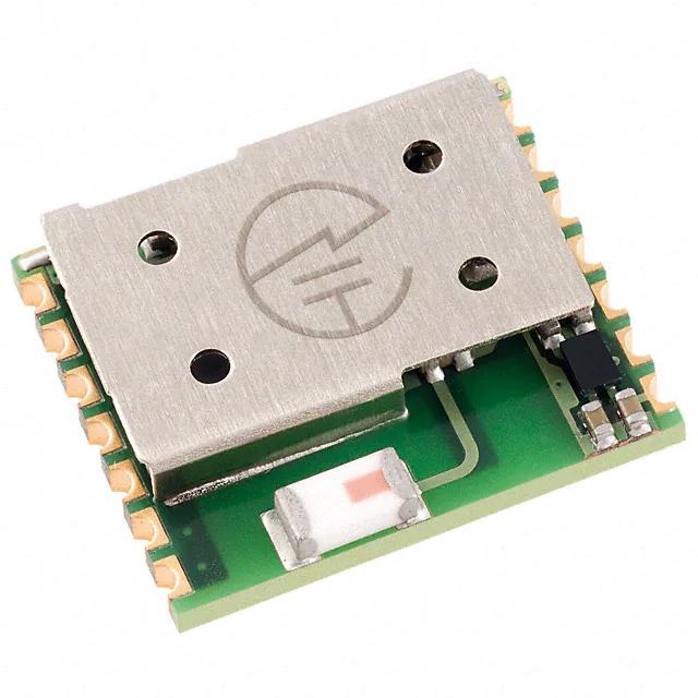
STMicroelectronics SPBT2632C2A.AT2
- Part No.:
- SPBT2632C2A.AT2
- Manufacturer:
- STMicroelectronics
- Category:
- RF Transceiver Modules and Modems
- Package:
- Module
- Datasheet:
-
 SPBT2632C2A.AT2.pdf
- Description:
- RF TXRX MOD BLUETOOTH CHIP SMD
- Quantity:
- Payment:

- Shipping:

Inventory:3,184
Please send an inquiry. Send us your inquiry, and we will respond immediately.
Product details
Overview
SPBT2632C2A.AT2 from STMicroelectronics is a Bluetooth v3.0 Class 2 surface-mount module with embedded Bluetooth stack, profiles, AT command firmware, onboard antenna, STM32 Cortex-M3 microcontroller, and STLC2690 Bluetooth radio. The module provides a ready-to-use Bluetooth serial communication platform for products that need wireless connectivity without a separate RF design.
For engineers reviewing the SPBT2632C2A.AT2 datasheet, SPBT2632C2A.AT2 pinout, SPBT2632C2A.AT2 application, or SPBT2632C2A.AT2 equivalent, this Bluetooth module is most relevant for serial cable replacement, M2M industrial control, service diagnostics, data acquisition, machine control, sensor monitoring, security systems, mobile health devices, and smartphone-connected accessories requiring UART control, embedded SPP support, iAP communication support, integrated antenna, and compact 11.6 mm × 13.5 mm module integration.
Technical Context
SPBT2632C2A.AT2 combines the Bluetooth radio, antenna, STM32-based host processing, embedded firmware, memory, and command interface in a surface-mount PCB module. The module supports Bluetooth v3.0 operation in the 2400 MHz to 2483.5 MHz band, Class 2 radio operation, UART host communication, seven GPIO lines, and firmware upgrade over UART, allowing the host microcontroller to communicate through a simple serial command structure rather than managing the Bluetooth stack directly.
The module operates from a 2.1 V to 3.6 V supply with 2.5 V typical operation. High-speed mode supports up to 1.5 Mbps data throughput, while low-power operation can reach 70 µA standby with deep sleep and an external 32.768 kHz low-power oscillator. RF performance includes -86 dBm typical receiver sensitivity under DH5 test conditions and +6 dBm typical transmitter output power into a 50 Ω load.
Key Specifications
| Parameter | Value and Actual Design Meaning |
|---|---|
| Device Type | Bluetooth v3.0 Class 2 RF transceiver module with embedded stack, profiles, AT command firmware, and onboard antenna. |
| Core Devices | Based on STLC2690 Bluetooth radio transceiver and STM32 Cortex-M3 microcontroller architecture. |
| Bluetooth Function | Fully embedded Bluetooth v3.0 with SPP, SDAP, GAP, RFCOMM, SDP, and L2CAP support for serial communication applications. |
| RF Band | 2400 MHz to 2483.5 MHz Bluetooth ISM-band operation. |
| Radio Class | Class 2 module with integrated antenna for short-range Bluetooth communication. |
| Receiver Sensitivity | -86 dBm typical sensitivity at BER below 0.001 with DH5, supporting reliable Bluetooth link reception within the module's class and antenna constraints. |
| Transmit Output Power | +6 dBm typical maximum output power into a 50 Ω load. |
| Supply Voltage | 2.1 V minimum, 2.5 V typical, 3.6 V maximum VIN supply range for low-voltage embedded products. |
| Processor and Memory | STM32 Cortex-M3 processor up to 72 MHz with 256 Kbytes Flash memory and 48 Kbytes RAM memory. |
| UART Interface | Main UART host interface with TXD, RXD, RTS, and CTS flow-control signals; AT command interface uses the main UART by default. |
| Data Throughput | Up to 1.5 Mbps data throughput, with high-speed CPU mode and UART-based host communication. |
| GPIO Resources | Seven GPIO pins plus one LPO input; GPIO pins can also support alternate functions such as SPI, I2S, ADC, DAC, and auxiliary UART functions depending on firmware configuration. |
| I/O Drive | GPIO outputs can sink or source 4 mA; pull-up and pull-down resistors are 80 kΩ to 120 kΩ when enabled. |
| Low-Power Operation | 70 µA standby current with deep sleep and external LPO, 520 µA page/inquiry scan with deep sleep and external LPO, and 25 µA Bluetooth power-down / CPU standby. |
| Security and Link Features | Authentication, 8-bit to 128-bit encryption key length, dynamic packet selection, dynamic power control, multipoint support, scatternet support, sniff mode, hold mode, and Bluetooth-WLAN coexistence features. |
| Package | 16-pin surface-mount PCB module, 11.6 mm × 13.5 mm × 2.9 mm, with integrated antenna. |
| Certification Context | BQE-qualified Bluetooth module with CE, FCC, IC, and TELEC certification coverage for the module version. |
| Operating Temperature | -40°C to +85°C operating temperature range for industrial and embedded wireless applications. |
Pinout & Package
SPBT2632C2A.AT2 is supplied as a 16-pin surface-mount PCB module measuring 11.6 mm × 13.5 mm × 2.9 mm with an integrated antenna and multilayer module construction. The module package supports compact Bluetooth integration, but the antenna area requires RF-aware placement: nearby metal, ground planes, power planes, trace routing, and mechanical obstructions should be kept away from the antenna region to preserve link performance.
| Pin / Terminal | Circuit Role | Design Meaning |
|---|---|---|
| Pin 1 - GPIO1 | General-purpose digital I/O with SPI MISO alternate function. | Provides configurable host or application I/O and can be used for firmware-defined functions such as SPI receive data where supported by the loaded firmware. |
| Pin 2 - GPIO2 | General-purpose digital I/O with SPI MOSI / I2S_SD alternate function. | Supports configurable I/O or serial peripheral data functions in applications that use module firmware exposing these alternate interfaces. |
| Pin 3 - GPIO3 | General-purpose digital I/O with SPI SCLK / I2S_CK alternate function. | Provides a configurable I/O or clock-related alternate function for SPI or I2S-capable firmware configurations. |
| Pin 4 - GPIO4 | General-purpose digital I/O with SPI SS / I2S_WS alternate function. | Supports configurable I/O, SPI select, or I2S word-select functions depending on firmware usage. |
| Pin 5 - GPIO5 | General-purpose digital I/O. | Provides a configurable digital signal for application status, control, or firmware-defined host interface use. |
| Pin 6 - GPIO6 | General-purpose digital I/O with DAC alternate function. | Provides configurable digital I/O or analog-related output capability under firmware control. |
| Pin 7 - GND | Ground terminal. | Provides the module ground reference and should be connected to the local system ground with a low-impedance connection. |
| Pin 8 - Vin | Main supply input. | Supplies the module over the 2.1 V to 3.6 V operating range, with 2.5 V typical operation. |
| Pin 9 - Boot0 | Boot-loader control input. | Controls boot-loader behavior for module programming or firmware-related service operations. |
| Pin 10 - RESETN | Active-low reset input. | Provides external reset control; the reset input is active low and is associated with the module reset timing requirements. |
| Pin 11 - CTS | UART flow-control input. | Works with RTS to support hardware flow control on the host UART interface and can also provide alternate ADC / auxiliary serial functions depending on firmware. |
| Pin 12 - RTS | UART flow-control output. | Provides the module-side hardware flow-control signal for managing UART traffic between the host processor and the Bluetooth module. |
| Pin 13 - RXD | UART receive-data input. | Receives serial command and data traffic from the host microcontroller and is part of the main AT command interface. |
| Pin 14 - TXD | UART transmit-data output. | Transmits serial response and Bluetooth data traffic from the module to the host microcontroller. |
| Pin 15 - LPO | Low-power oscillator input. | Accepts an optional 32.768 kHz external low-power oscillator signal for deep sleep and sniff-mode power optimization. |
| Pin 16 - GPIO7 | General-purpose digital I/O with ADC alternate function. | Provides configurable I/O or analog-input related functionality depending on firmware configuration and application use. |
Key Features
- Bluetooth v3.0 Class 2 module with embedded stack, profiles, and AT command firmware.
- Integrated antenna and complete RF-ready module construction for simplified Bluetooth product integration.
- STM32 Cortex-M3 processor architecture with 256 Kbytes Flash memory and 48 Kbytes RAM memory.
- Main UART host interface with TXD, RXD, RTS, and CTS hardware flow-control signals.
- Up to 1.5 Mbps data throughput and UART-based command/control operation.
- Seven GPIO pins plus one LPO input, with several alternate peripheral functions depending on firmware configuration.
- Supports authentication, encryption, multipoint operation, scatternet support, sniff mode, hold mode, and Bluetooth-WLAN coexistence behavior.
- 2.1 V to 3.6 V supply range, -40°C to +85°C operating temperature range, and compact 11.6 mm × 13.5 mm × 2.9 mm module format.
Applications
| Serial Cable Replacement | Industrial M2M Control |
|---|---|
|
Use Scenario: Embedded products that replace wired serial links with Bluetooth communication. Module Role: UART-controlled Bluetooth module with embedded SPP support and AT command firmware. Use Value: The host processor can send serial data through SPBT2632C2A.AT2 without implementing the Bluetooth stack or tuning a discrete RF path. |
Use Scenario: Industrial control nodes, machine-control terminals, and M2M equipment requiring local wireless communication. Module Role: Integrated Bluetooth modem with UART host interface, GPIO resources, and onboard antenna. Use Value: The embedded stack and certified RF design reduce radio development effort while keeping the host MCU focused on the industrial control application. |
| Sensor Monitoring and Security Systems | Mobile Health and Smartphone Accessories |
|
Use Scenario: Sensor nodes, service diagnostic tools, data acquisition equipment, and security-system peripherals. Module Role: Low-power Bluetooth communication module with standby, deep-sleep, and optional LPO-assisted power modes. Use Value: 70 µA standby with external LPO and UART-based control help battery-powered monitoring devices maintain wireless availability with reduced host burden. |
Use Scenario: Mobile health products and accessories communicating with Bluetooth-enabled smartphones or Apple iOS/MFi products. Module Role: Bluetooth v3.0 module with AT command firmware, SPP support, and iAP communication support. Use Value: The ready-to-use command interface and smartphone communication support reduce embedded software complexity in accessory and portable-device designs. |
Equivalent & Alternatives
When evaluating SPBT2632C2A.AT2 equivalent modules, engineers should compare Bluetooth version, radio class, antenna integration, UART command interface, SPP and iAP firmware behavior, supply voltage, GPIO count, module dimensions, RF certification coverage, host-interface pinout, and whether a design requires a Class 2 or longer-range Class 1 radio configuration.
| Alternative Part | Technical Difference | Application Difference | Selection Advice |
|---|---|---|---|
| SPBT2632C1A.AT2 | Bluetooth v3.0 Class 1 module with onboard antenna and AT2 command firmware, using a larger 15.2 mm × 26.9 mm × 2.9 mm module format. | Better suited when longer Bluetooth range or higher radio class is needed and the PCB has enough area for the larger module. | Select SPBT2632C2A.AT2 for compact Class 2 designs; select SPBT2632C1A.AT2 when Class 1 range is more important than module footprint. |
| SPBT2532C2.AT2 | Older ST Bluetooth v2.1 + EDR Class 2 module with SPP and AT2 command support, 3.3 V typical supply, four GPIOs, and a different 10.5 mm × 13.5 mm × 2.5 mm module format. | Relevant for legacy Bluetooth v2.1 + EDR designs but not a direct electrical or software match for Bluetooth v3.0 SPBT2632C2A.AT2 layouts. | Use only when the system requirement matches the older Bluetooth v2.1 + EDR module behavior, voltage plan, firmware interface, and mechanical footprint. |
Compared with SPBT2632C1A.AT2, SPBT2632C2A.AT2 is optimized for smaller Class 2 Bluetooth integration with an 11.6 mm × 13.5 mm form factor. SPBT2632C2A.AT2 vs SPBT2632C1A.AT2 selection depends mainly on required Bluetooth range, available board area, antenna placement constraints, certification reuse needs, and the host firmware's AT2 command workflow.
Quality
SPBT2632C2A.AT2 should be sourced as original STMicroelectronics components through traceable and controlled supply channels. Quality verification procedures may include module marking inspection, tray and label verification, solder-pad and antenna-area inspection, RoHS / ECOPACK compliance review, solderability testing, UART communication test, AT command response verification, Bluetooth link test, RF output and receive-function screening, low-power-mode current inspection, and incoming inspection according to embedded wireless product production requirements.
Availability
SPBT2632C2A.AT2 is available at Aetrix Electronics and suitable for serial cable replacement, M2M industrial control, service diagnostics, sensor monitoring, security systems, mobile health devices, and Bluetooth smartphone accessories requiring stable component supply and repeatable production support.
Supply support may include scheduled delivery planning, volume procurement support, BOM continuity assistance, traceable sourcing management, and long-term availability support for embedded device manufacturers, industrial control builders, wireless accessory developers, repair groups, contract manufacturers, and legacy Bluetooth product owners.
For production deployment, confirming the 16-pin module footprint, onboard antenna keepout, 2.1 V to 3.6 V supply range, UART signal levels, LPO requirement, firmware command set, RF certification needs, tray handling, environmental specifications, and sourcing continuity helps reduce procurement risk and improve manufacturing stability.
Manufacturer
STMicroelectronics supplies wireless connectivity modules, RF components, microcontrollers, sensors, power-management ICs, protection devices, and embedded semiconductor solutions for industrial, consumer, automotive, communication, and portable applications. SPBT2632C2A.AT2 belongs to ST's Bluetooth module portfolio for embedded wireless serial communication and smartphone accessory connectivity.
FAQ
What is SPBT2632C2A.AT2 used for?
SPBT2632C2A.AT2 is used to add Bluetooth v3.0 Class 2 wireless communication to embedded products. It is commonly used for serial cable replacement, industrial M2M communication, service diagnostics, data acquisition equipment, sensor monitoring, security systems, mobile health devices, and smartphone-connected accessories.
Is SPBT2632C2A.AT2 a Bluetooth IC or a module?
SPBT2632C2A.AT2 is a surface-mount Bluetooth module, not a bare Bluetooth IC. It integrates the Bluetooth radio, STM32-based processing, embedded stack, AT command firmware, memory, and onboard antenna in a compact PCB module, allowing the host system to communicate through UART instead of designing the RF section from individual components.
Which host interface does SPBT2632C2A.AT2 use?
SPBT2632C2A.AT2 uses a UART host interface with RXD, TXD, RTS, and CTS signals. The AT command interface uses the main UART by default, which allows the host microcontroller to configure Bluetooth functions, exchange serial data, and manage connection behavior using command-based firmware rather than a host-side Bluetooth protocol stack.
What supply voltage does SPBT2632C2A.AT2 require?
SPBT2632C2A.AT2 operates from a VIN supply range of 2.1 V to 3.6 V, with 2.5 V typical operation. Host interface design should match the module's I/O voltage requirements, and the reset input should be treated carefully because its maximum input level is lower than 5 V tolerant GPIO and UART pins.
What should be considered in SPBT2632C2A.AT2 antenna layout?
SPBT2632C2A.AT2 includes an onboard antenna, so PCB placement directly affects RF performance. The region around the antenna should be kept clear of ground planes, power planes, traces, and metal structures. Traces should not be routed underneath the module, and all ground connections should be made with low impedance to maintain RF stability.
Does SPBT2632C2A.AT2 support low-power operation?
SPBT2632C2A.AT2 supports active, sleep, deep sleep, sniff, hold, and power-down related operating modes. With an external 32.768 kHz low-power oscillator, standby current can reach 70 µA in deep sleep, while Bluetooth power-down / CPU standby current is listed at 25 µA, making the module usable in power-sensitive embedded wireless products.
What is the difference between SPBT2632C2A.AT2 and SPBT2632C1A.AT2?
SPBT2632C2A.AT2 is the compact Bluetooth v3.0 Class 2 module with an 11.6 mm × 13.5 mm × 2.9 mm form factor. SPBT2632C1A.AT2 is the related Class 1 module with a larger 15.2 mm × 26.9 mm × 2.9 mm size. The Class 1 version is selected when longer Bluetooth range is more important than board footprint.
What package format is used by SPBT2632C2A.AT2?
SPBT2632C2A.AT2 uses a 16-pin surface-mount PCB module package measuring 11.6 mm × 13.5 mm × 2.9 mm. The module is intended for reflow assembly and includes the antenna, Bluetooth RF section, microcontroller, memory, firmware, and host-interface pins in a compact module footprint.
SPBT2632C2A.AT2 Specifications
- Product attributes
- Attribute value
- Manufacturer:
- STMicroelectronics
- Series:
- -
- Package/Case:
- Module
- Packaging:
- Tray
- Product Status:
- Obsolete
- Programmable:
- Not Verified
- RF Family/Standard:
- Bluetooth
- Protocol:
- Bluetooth v3.1
- Modulation:
- -
- Frequency:
- 2.4GHz
- Data Rate:
- 560kbps
- Power - Output:
- 0dBm
- Sensitivity:
- -86dBm
- Serial Interfaces:
- UART
- Antenna Type:
- Integrated, Chip
- Utilized IC / Part:
- STLC2690
- Memory Size:
- 256kB Flash, 48kB RAM
- Voltage - Supply:
- 2.5V
- Current - Receiving:
- 2.7mA
- Current - Transmitting:
- 11.2mA
- Mounting Type:
- Surface Mount
- Operating Temperature:
- -40°C ~ 85°C
SPBT2632C2A.AT2 FAQ
1.How can I place an order for SPBT2632C2A.AT2 through Aetrix?
Please submit a Request for Quotation (RFQ) for SPBT2632C2A.AT2 on Aetrix. Our sales agent will provide a competitive quotation and guide you through the order confirmation once you accept the terms.
2.Are the price and stock information for SPBT2632C2A.AT2 reliable?
The price and inventory of SPBT2632C2A.AT2 are updated periodically and may fluctuate due to market conditions. Stock and pricing data are typically refreshed every 24 hours. Quotation validity for SPBT2632C2A.AT2 is usually 5 days.
3.What payment methods are accepted for SPBT2632C2A.AT2?
We accept Wire Transfer, PayPal, Credit Card, Western Union, MoneyGram, and Escrow for SPBT2632C2A.AT2 transactions.
Note: Certain payment methods may incur a processing fee.
4.How is shipping managed for SPBT2632C2A.AT2?
SPBT2632C2A.AT2 orders can be shipped via leading logistics carriers, including DHL, UPS, FedEx, TNT, or Registered Mail.
Once your SPBT2632C2A.AT2 order is processed, you will receive an email with the shipment details and tracking number.
Note: Tracking information may take up to 24 hours to appear. Express delivery typically takes 3–5 business days.
5.How can I obtain technical support or documentation for SPBT2632C2A.AT2?
For technical support, including SPBT2632C2A.AT2 datasheets, pinout diagrams, or application guidance, please contact our engineering support team. They can provide detailed documentation and assistance for your SPBT2632C2A.AT2 requirements.
6.How does Aetrix verify that SPBT2632C2A.AT2 is sourced from the original manufacturer or authorized distributors?
All SPBT2632C2A.AT2 products on Aetrix are procured from qualified distributors and authorized channels. Our dedicated quality assurance team conducts strict verification, including traceability checks and, if necessary, third-party testing. This ensures that SPBT2632C2A.AT2 meets industry standards.
7.What is the process for return or replacement of SPBT2632C2A.AT2?
All SPBT2632C2A.AT2 units undergo pre-shipment inspection (PSI). If there is an issue with SPBT2632C2A.AT2, returns or replacements are accepted under the following conditions:
1.Quantity discrepancies, incorrect items, or visible external defects (such as breakage or corrosion), acknowledged by Aetrix.
2.The issue is reported within 90 days of delivery.
3.The SPBT2632C2A.AT2 part is unused and in its original packaging.
Return procedure for SPBT2632C2A.AT2:
1.Submit a request within 90 days.
2.Obtain a Return Material Authorization (RMA) from Aetrix.
SPBT2632C2A.AT2 Tags

-
ESP32-C3FH4
Espressif Systems
-
ESP32-S2FH4
Espressif Systems
-
ESP32-S2FN4R2
Espressif Systems
-
ESP32-C3-MINI-1-N4
Espressif Systems
-
ESP32-C3-WROOM-02-N4
Espressif Systems
-
ESP32-C3-MINI-1U-N4
Espressif Systems
-
ESP32-C3-MINI-1U-H4
Espressif Systems
-
ESP32-C3-WROOM-02U-N4
Espressif Systems
-
ESP32-H2-MINI-1-N4
Espressif Systems
-
ESP32-H2-MINI-1-H4
Espressif Systems
_viewa.jpg)
-
ESP32-MINI-1-N4
Espressif Systems
-
ESP32-S2-MINI-2-N4R2
Espressif Systems
Tech Hub

An engineering guide to LED driver operation, constant-current and constant-voltage outputs, linear and switching topologies, dimming, IC selection, calculations, replacement compatibility, and fault c…

Operational amplifier guide covering op amp basics, feedback, ideal vs real op amps, common configurations, buffer circuits, offset, bias current, gain-bandwidth, slew rate, rail-to-rail limits and sel…

Jumper cables guide covering safe connection order, red and black clamp placement, final ground connection, cable gauge, length, clamp quality, copper vs CCA cables, jump starter comparison and battery…

LDO regulator guide covering low dropout voltage, power dissipation, thermal design, PSRR, output noise, capacitor stability, adjustable LDO circuits, LDO vs buck converter and datasheet selection chec…

Conditional Access Module guide covering CAM meaning, CI/CI+ interface, smart card authorization, DVB security workflow, TV and set-top box compatibility, internal electronics, ESD protection, connecto…

Guide to electronic component obsolescence covering EOL risk, PCN/PDN notices, last-time buy planning, replacement options, form-fit-function validation, counterfeit risk and BOM lifecycle management.

18650 battery guide covering lithium-ion cell basics, 3.6V/3.7V voltage, 4.2V charging, mAh and Wh capacity, protected cells, chargers, BMS, series-parallel packs, holders, welding and sourcing checks.…

Hall effect sensor guide covering working principle, linear and digital sensors, Arduino circuits, current sensing, speed detection, automotive applications, A3144 examples, signal filtering and datash…

Product Change Notification guide for electronic components, covering PCN meaning, PCN vs PDN/EOL, common change types, risk levels, form-fit-function review, engineering validation, BOM control, LTB/L…

A practical guide to blend door actuators, covering HVAC function, symptoms, location, AC and heater issues, reset and calibration, replacement cost, electrical diagnosis, compatibility checks, and rep…


