
 My Inquiry
 My Account


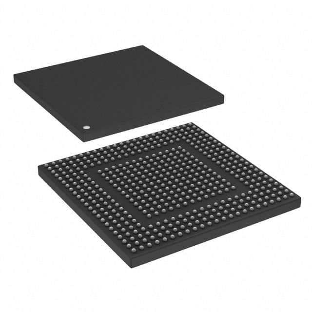
NXP Semiconductors SPC5675KF0VMS2
- Part No.:
- SPC5675KF0VMS2
- Manufacturer:
- NXP Semiconductors
- Category:
- Microcontrollers
- Package:
- 473-LFBGA
- Datasheet:
-
 SPC5675KF0VMS2.pdf
- Description:
- IC MCU 32BIT 2MB FLASH 473MAPBGA
- Quantity:
- Payment:

- Shipping:

Inventory:3,922
Please send an inquiry. Send us your inquiry, and we will respond immediately.
Product details
Overview
SPC5675KF0VMS2 from NXP Semiconductors is a dual-core 32-bit Power Architecture® MCU with e200z7d cores operating up to 180 MHz, 512 KB SRAM (ECC), 2 MB code flash (ECC), and integrated FlexPWM/FlexCAN/FlexRay for automotive ADAS and HEV motor control. It supports lock-step safety operation per ISO 26262 ASIL D and operates from –40 °C to 150 °C junction temperature.
For engineers reviewing the SPC5675KF0VMS2 datasheet, SPC5675KF0VMS2 pinout, SPC5675KF0VMS2 application, or SPC5675KF0VMS2 equivalent, key selection criteria include dual-core lock-step reliability, on-chip PDI for CMOS imaging, FMPLL-based jitter-free PWM timing, and 473-pin MAPBGA package compatibility with DDR and EBI interfaces.
Technical Context
The SPC5675KF0VMS2 implements two e200z7d cores with Harvard architecture, 16 KB instruction and 16 KB data caches per core (EDC/parity protected), MMU with 64 TLB entries, and SPE2 auxiliary processing unit. It uses Variable Length Encoding (VLE) for reduced code footprint and supports both lock-step and decoupled parallel modes.
Its safety architecture includes Sphere of Replication (SoR) for critical peripherals, redundancy checkers on PBRIDGE/Flash/SRAM outputs, FCCU fault collection, boot-time MBIST/LBIST, and replicated STM/SWT modules - all aligned to ASIL D requirements for radar, LIDAR, and 3-phase motor control systems.
Key Specifications
| Parameter | Value and Actual Design Meaning |
|---|---|
| Core Architecture | Dual e200z7d Power Architecture® cores with VLE, SPE2, and MMU - enables deterministic real-time execution and legacy PPC ISA compatibility. |
| Max Core Frequency | 180 MHz (+2% FM) - delivers high computational throughput for sensor fusion and motor control algorithms without external clock synthesis. |
| On-Chip Memory | 2 MB ECC-protected code flash + 64 KB ECC data flash + 512 KB ECC SRAM - ensures data integrity in safety-critical automotive storage and runtime variables. |
| Safety Certification | ISO 26262 ASIL D compliant via lock-step SoR, FCCU, replicated STM/SWT, and hardware BIST - eliminates need for external safety monitors in certified ECUs. |
| Peripheral Integration | 4 FlexCAN 2.0B modules (32 MBUF each), 3 FlexPWM units (4×3 channels), 4 LINFlex, 3 DSPI, FlexRay v2.1 (dual channel, 10 Mbit/s), PDI - consolidates ADAS and powertrain interface functions onto single die. |
| Operating Temperature | Junction range –40 °C to +150 °C - qualified for under-hood HEV traction inverters and radar ECU environments without derating. |
| Package & Pin Count | 473-pin MAPBGA, 19 mm × 19 mm - supports DDR, EBI, and PDI I/O routing while meeting automotive thermal and mechanical reliability standards. |
Pinout & Package
SPC5675KF0VMS2 is housed in a 473-pin MAPBGA package (19 mm × 19 mm, 0.8 mm pitch) with exposed thermal pad. This package supports DDR, EBI, and PDI interfaces and is mechanically and thermally optimized for automotive under-hood applications.
| Pin/Terminal | Circuit Role | Design Meaning |
|---|---|---|
| VDD_DDR / VDD_PDI | Power supply | 1.8–3.3 V domain for DDR/PDI interface - enables direct connection to mobile DDR or image sensor I/O without level-shifting. |
| CLKIN / XOSC | External clock input | 4–40 MHz crystal or oscillator input for primary FMPLL reference - provides stable base clock for system and auxiliary PLLs. |
| FMPLL_VCO | VCO power supply | 2.5 V regulated supply for FMPLL voltage-controlled oscillator - isolates sensitive analog PLL circuitry from digital noise. |
| PDI_DATA[15:0] | Parallel data bus | 16-bit bidirectional pixel/data bus for CMOS image sensors or ADCs - supports up to system bus frequency with programmable edge capture. |
| FLEXRAY_A_TX / FLEXRAY_B_TX | FlexRay differential output | Dual-channel FlexRay physical layer transmit pairs - enables time-triggered communication for x-by-wire and domain controller applications. |
| ADC0_IN0–ADC0_IN21 | Analog input | 22 dedicated single-ended ADC input pins for 12-bit conversion - routed to four independent ADC modules with CTU-triggered sampling. |
Key Features
| Feature | Design Value |
|---|---|
| Lock-step dual-core execution | Hardware-enforced identical instruction execution across two e200z7d cores with automatic fault detection and fail-safe shutdown - meets ASIL D diagnostic coverage targets without software overhead. |
| Programmable FMPLL modulation | ±2% triangular frequency modulation at 25 kHz - reduces electromagnetic interference peaks during high-speed PWM and Ethernet transmission in dense automotive ECU layouts. |
| Parallel Data Interface (PDI) | Configurable 8–16 bit parallel capture with VSYNC/HSYNC/PIXCLK sync and FIFO thresholds - enables direct integration of CMOS radar or surround-view cameras without FPGA glue logic. |
| FlexPWM with auxiliary PLL | Independent clock source for PWM generation - allows jitter-free, high-resolution motor control timing even when system clock is modulated or dynamically scaled. |
| Cross Triggering Unit (CTU) | Hardware-synchronized ADC sampling triggered by FlexPWM edges or eTimer events - eliminates CPU polling and guarantees sub-microsecond phase alignment for field-oriented control loops. |
| Replicated System Timer (STM) | Dual STM modules with synchronized compare registers - provides redundant OS tick and hardware task protection required by AUTOSAR OS 4.x for safety-critical scheduling. |
Applications
| Radar Signal Processing ECU | Hybrid Electric Vehicle Traction Inverter |
|---|---|
Use Scenario: Real-time FFT and CFAR processing of 77 GHz radar echo data from multiple antennas using DSP-accelerated SPE2 units. IC Role / Device Role / Timing Role: Primary compute engine with lock-step cores executing sensor fusion algorithms; PDI ingests raw ADC samples from RF front-end; FMPLL supplies low-jitter clocks to ADC and DAC interfaces. Use Value: On-die ECC memory and hardware BIST ensure algorithm integrity over 15-year vehicle lifetime; 150 °C junction rating permits placement near radar RF module without heatsink. |
Use Scenario: Closed-loop FOC control of dual 3-phase permanent magnet motors in P4 HEV architecture with regenerative braking coordination. IC Role / Device Role / Timing Role: Motor control hub managing FlexPWM outputs, CTU-synchronized current sensing, and CAN/FlexRay gateway functions; auxiliary FMPLL drives precise PWM carrier frequencies. Use Value: Integrated 512 KB SRAM stores multiple motor profiles and calibration tables; replicated eTimer and STM guarantee deterministic interrupt latency for <1 µs current loop deadlines. |
| Automotive LIDAR Point Cloud Processor | ADAS Domain Controller Gateway |
Use Scenario: Time-of-flight calculation and point cloud registration from multi-channel SPAD arrays, fused with camera and radar inputs. IC Role / Device Role / Timing Role: High-bandwidth data aggregator using PDI for sensor streaming and FlexCAN/FlexRay for inter-ECU messaging; dual-core decoupled mode runs perception stack and safety monitor concurrently. Use Value: 473-pin MAPBGA provides dedicated DDR interface for real-time point cloud buffering; ASIL D-certified SoR architecture validates safety-critical path outputs independently. |
Use Scenario: Centralized communication hub aggregating CAN FD, LIN, Ethernet, and FlexRay traffic between ADAS sensors, chassis controllers, and infotainment. IC Role / Device Role / Timing Role: Network convergence processor with 4 FlexCAN modules, FEC, and 3 LINFlex ports; crossbar switch enables concurrent DMA transfers across all interfaces. Use Value: Integrated CRC units and ECC memory protect firmware updates over-the-air; Nexus Class 3+ debug enables secure trace and live analysis during SIL3 validation testing. |
Equivalent & Alternatives
The following parts are listed as comparable options for similar automotive microcontroller applications.
| Alternative Part | Technical Difference | Application Difference | Selection Advice |
|---|---|---|---|
| MPC5674KF0VPS | Same dual e200z7d core, but 384 KB SRAM (ECC), 1.5 MB flash, 257-pin MAPBGA (14 × 14 mm) - lacks DDR controller and EBI. | Targeted at cost-optimized ADAS camera modules without DDR or external memory expansion needs. | Select when PDI + LIN/CAN suffices and DDR/EBI are unnecessary; smaller package reduces PCB area and cost. |
| S32K344WFT0VLQ | ARM Cortex-M7 dual-core (lock-step), 4 MB flash, 1.5 MB RAM, 256-pin BGA - no PDI, no FlexRay, different safety architecture (HSM-based). | Designed for zonal ECU consolidation with Ethernet AVB and HSE security; not suitable for radar/LIDAR sensor interfacing. | Choose for next-gen SOA architectures requiring AUTOSAR Adaptive support and cryptographic acceleration - not a functional replacement for SPC5675KF0VMS2's sensor-centric features. |
Compared with MPC5674KF0VPS, SPC5675KF0VMS2 adds DDR/EBI and 128 KB more SRAM for sensor buffer expansion; versus S32K344WFT0VLQ, it retains native PDI, FlexRay, and Power Architecture toolchain continuity essential for legacy radar platform migration.
Availability
SPC5675KF0VMS2 is available at Aetrix Electronics and suitable for automotive radar ECUs, hybrid electric vehicle traction inverters, LIDAR point cloud processors, and ADAS domain controllers requiring stable component supply across extended product lifecycles.
Supply support for SPC5675KF0VMS2 includes scheduled delivery planning, volume procurement assistance, BOM continuity management, traceable sourcing, and lifecycle availability coordination for OEM customers, industrial embedded developers, connected-device designers, and electronics production programs.
Manufacturer
NXP Semiconductors is a global semiconductor leader focused on automotive, industrial, IoT, and communication infrastructure solutions, with deep expertise in safety-critical embedded systems and secure connectivity.
The SPC5675KF0VMS2 belongs to NXP's MPC5675K family - a SafeAssure solution engineered specifically for advanced driver assistance systems (ADAS) and high-temperature hybrid electric vehicle powertrain control, emphasizing ASIL D compliance and sensor interface integration.
FAQ
What is the maximum operating junction temperature for the SPC5675KF0VMS2?
The SPC5675KF0VMS2 is rated for a junction temperature range of –40 °C to +150 °C. This specification is validated per AEC-Q100 Grade 0 and enables direct mounting in high-thermal-load locations such as near radar transceivers or HEV inverter modules. The device maintains full functionality and timing compliance across this range without derating, as confirmed in Section 3.3 of the MPC5675K datasheet Rev. 9.
Does the SPC5675KF0VMS2 support DDR memory interfaces?
Yes, the SPC5675KF0VMS2 integrates a 16-bit mobile DDR (mDDR) controller supporting up to 8 MB address space, as documented in Section 1.6.11 of the MPC5675K datasheet. This capability is exclusive to the 473-pin MAPBGA variant and requires proper termination and layout per NXP's AN4927 guidelines. The SPC5675KF0VMS2 does not support standard DDR2 or LPDDR4.
How many FlexCAN modules does the SPC5675KF0VMS2 include, and what protocol versions are supported?
The SPC5675KF0VMS2 includes four fully independent FlexCAN modules, each supporting CAN 2.0B Active protocol with 32 message buffers. All modules implement ISO 11898-1:2015 compliance and support programmable acceptance filtering, listen-only mode, and hardware timestamping. No CAN FD capability is integrated - this is explicitly stated in Table 1 and Section 1.6.16 of the MPC5675K datasheet Rev. 9.
Is the SPC5675KF0VMS2 pin-compatible with other MPC5675K variants?
No, the SPC5675KF0VMS2 is not pin-compatible with lower-pin-count MPC5675K variants like the 257-pin version. Its 473-pin MAPBGA package includes dedicated balls for DDR, EBI, and additional FlexCAN/FlexRay signals absent in smaller packages. Pin compatibility is only maintained within the same 473-pin MAPBGA family (e.g., SPC5675KF0VMS2 and MPC5675KF0VPS), as verified in Section 4.1 mechanical drawings.
What debug interface does the SPC5675KF0VMS2 provide, and what class level is supported?
The SPC5675KF0VMS2 features a Nexus Class 3+ debug interface supporting real-time trace of both e200z7d cores, SRAM port access, and hardware breakpoints - as specified in Section 1.5 and Figure 1 of the MPC5675K datasheet. This enables non-intrusive profiling and safety validation per ISO 26262 tool qualification requirements, with full support for Lauterbach TRACE32 and iSystem winIDEA debug tools.
SPC5675KF0VMS2 Specifications
- Product attributes
- Attribute value
- Manufacturer:
- NXP Semiconductors
- Package/Case:
- 473-LFBGA
- Series:
- MPC56xx Qorivva
- Packaging:
- Tray
- Product Status:
- Active
- Programmable:
- Not Verified
- Core Processor:
- e200z7d
- Core Size:
- 32-Bit Dual-Core
- Speed:
- 180MHz
- Connectivity:
- CANbus, EBI/EMI, Ethernet, FlexRay, I2C, LINbus, SPI
- Peripherals:
- DMA, POR, PWM, WDT
- Number of I/O:
- -
- Program Memory Size:
- 2MB (2M x 8)
- Program Memory Type:
- FLASH
- EEPROM Size:
- 64K x 8
- RAM Size:
- 512K x 8
- Voltage - Supply (Vcc/Vdd):
- 1.14V ~ 5.5V
- Data Converters:
- A/D 34x12b
- Oscillator Type:
- Internal
- Operating Temperature:
- -40°C ~ 105°C (TA)
- Grade:
- -
- Qualification:
- -
- Mounting Type:
- Surface Mount
- Supplier Device Package:
SPC5675KF0VMS2 FAQ
1.How can I place an order for SPC5675KF0VMS2 through Aetrix?
Please submit a Request for Quotation (RFQ) for SPC5675KF0VMS2 on Aetrix. Our sales agent will provide a competitive quotation and guide you through the order confirmation once you accept the terms.
2.Are the price and stock information for SPC5675KF0VMS2 reliable?
The price and inventory of SPC5675KF0VMS2 are updated periodically and may fluctuate due to market conditions. Stock and pricing data are typically refreshed every 24 hours. Quotation validity for SPC5675KF0VMS2 is usually 5 days.
3.What payment methods are accepted for SPC5675KF0VMS2?
We accept Wire Transfer, PayPal, Credit Card, Western Union, MoneyGram, and Escrow for SPC5675KF0VMS2 transactions.
Note: Certain payment methods may incur a processing fee.
4.How is shipping managed for SPC5675KF0VMS2?
SPC5675KF0VMS2 orders can be shipped via leading logistics carriers, including DHL, UPS, FedEx, TNT, or Registered Mail.
Once your SPC5675KF0VMS2 order is processed, you will receive an email with the shipment details and tracking number.
Note: Tracking information may take up to 24 hours to appear. Express delivery typically takes 3–5 business days.
5.How can I obtain technical support or documentation for SPC5675KF0VMS2?
For technical support, including SPC5675KF0VMS2 datasheets, pinout diagrams, or application guidance, please contact our engineering support team. They can provide detailed documentation and assistance for your SPC5675KF0VMS2 requirements.
6.How does Aetrix verify that SPC5675KF0VMS2 is sourced from the original manufacturer or authorized distributors?
All SPC5675KF0VMS2 products on Aetrix are procured from qualified distributors and authorized channels. Our dedicated quality assurance team conducts strict verification, including traceability checks and, if necessary, third-party testing. This ensures that SPC5675KF0VMS2 meets industry standards.
7.What is the process for return or replacement of SPC5675KF0VMS2?
All SPC5675KF0VMS2 units undergo pre-shipment inspection (PSI). If there is an issue with SPC5675KF0VMS2, returns or replacements are accepted under the following conditions:
1.Quantity discrepancies, incorrect items, or visible external defects (such as breakage or corrosion), acknowledged by Aetrix.
2.The issue is reported within 90 days of delivery.
3.The SPC5675KF0VMS2 part is unused and in its original packaging.
Return procedure for SPC5675KF0VMS2:
1.Submit a request within 90 days.
2.Obtain a Return Material Authorization (RMA) from Aetrix.
SPC5675KF0VMS2 Tags

-
ATTINY4-TSHR
Microchip Technology
-
ATTINY10-TSHR
Microchip Technology
-
ATTINY10-TS8R
Microchip Technology

-
ATTINY202-SSNR
Microchip Technology
-
ATTINY202-SSFR
Microchip Technology
-
ATTINY402-SSNR
Microchip Technology

-
PIC16F15213T-I/MF
Microchip Technology
-
PIC16F15213-E/MF
Microchip Technology

-
PIC10F200T-I/OT
Microchip Technology
-
ATTINY412-SSNR
Microchip Technology
-
PIC10F202T-I/OT
Microchip Technology

-
ATTINY404-SSNR
Microchip Technology
Tech Hub

A practical engineering guide to 3.3V and 5V logic compatibility, input thresholds, resistor dividers, translator ICs, MOSFET level shifting, I2C pull-ups, timing limits and power-sequencing risks.

The 74HC595 uses push-pull logic outputs, while the TPIC6B595 uses 50 V open-drain DMOS sinks for higher-power loads. This guide compares timing, current limits, 3.3 V interfacing, load wiring, thermal…

The 74HC595 converts serial data into eight stable parallel outputs. This guide covers pin functions, shift and storage timing, OE and MR behavior, drive-current limits, cascading, voltage compatibilit…

A technical comparison of level-sensitive latches and edge-triggered flip-flops, covering timing windows, setup and hold limits, master–slave operation, time borrowing, race-through, HDL inference and…

A D latch stores one bit while Enable controls when data can pass. This reference covers gate-level operation, truth tables, transparency, setup and hold timing, LE versus OE, common ICs and practical …

An SR latch stores one bit through cross-coupled feedback. This engineering reference covers NOR and NAND implementations, truth tables, forbidden-state recovery, gated operation, switch debouncing, fa…

Latch circuits retain one bit through feedback. This technical reference covers SR and D latches, truth tables, transparency, timing limits, latch-versus-flip-flop behavior, applications and common log…

An engineering guide to LED driver operation, constant-current and constant-voltage outputs, linear and switching topologies, dimming, IC selection, calculations, replacement compatibility, and fault c…

Operational amplifier guide covering op amp basics, feedback, ideal vs real op amps, common configurations, buffer circuits, offset, bias current, gain-bandwidth, slew rate, rail-to-rail limits and sel…

Jumper cables guide covering safe connection order, red and black clamp placement, final ground connection, cable gauge, length, clamp quality, copper vs CCA cables, jump starter comparison and battery…


