
 My Inquiry
 My Account


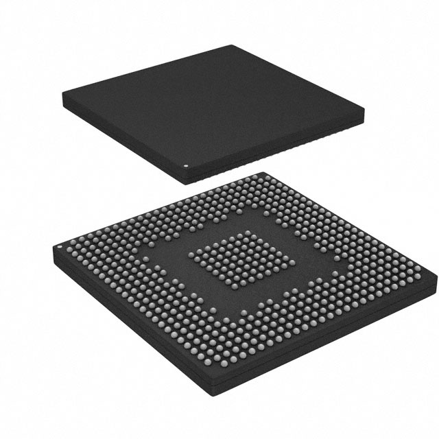
NXP Semiconductors SPC5777CK3MMO3R
- Part No.:
- SPC5777CK3MMO3R
- Manufacturer:
- NXP Semiconductors
- Category:
- Microcontrollers
- Package:
- 516-BGA
- Datasheet:
-
 SPC5777CK3MMO3R.pdf
- Description:
- IC MCU 32BIT 8MB FLASH 516MAPBGA
- Quantity:
- Payment:

- Shipping:

Inventory:1,837
Please send an inquiry. Send us your inquiry, and we will respond immediately.
Product details
Overview
SPC5777CK3MMO3R from NXP Semiconductors is a high-integrity automotive microcontroller featuring three dual-issue e200z7 Power Architecture cores (two in lockstep), 8 MB on-chip flash, 512 KB SRAM (including 64 KB standby RAM), dual PLLs, and integrated safety modules including FCCU, ERM, and CSE compliant with SHE v1.1. It targets engine control units, transmission controllers, and battery management systems requiring ASIL-D compliance.
For engineers reviewing the SPC5777CK3MMO3R datasheet, SPC5777CK3MMO3R pinout, SPC5777CK3MMO3R application, or SPC5777CK3MMO3R equivalent, key selection criteria include dual-core lockstep execution, 264 MHz computational frequency, integrated FlexCAN and M_CAN FD interfaces, hardware ECC across crossbar and memory subsystems, and support for ISO 26262 ASIL-D decomposition via built-in safety monitors and error injection capability.
Technical Context
The SPC5777CK3MMO3R implements a triple-core architecture with two computational e200z7 cores operating in lockstep for fault detection and one checker core, all supported by hardware cache coherency, 16 KB I-Cache/D-Cache per computational core, and VLE instruction encoding for code density. Its crossbar switch enables concurrent access to flash, SRAM, and peripherals with end-to-end ECC protection.
It integrates dual PLLs-one for stable peripheral clocking (132/153 MHz) and one for frequency-modulated computational shell operation (264/306 MHz)-alongside dedicated safety infrastructure: Fault Collection and Control Unit (FCCU), Error Reporting Module (ERM), Clock Monitor Units (CMUs), and Tamper Detection Module (TDM), enabling systematic ASIL-D implementation per ISO 26262.
Key Specifications
| Parameter | Value and Actual Design Meaning |
|---|---|
| Core Architecture | Three e200z7 32-bit Power Architecture cores: two dual-issue computational cores in lockstep + one checker core |
| Max Operating Frequency | 264 MHz (computational shell); 132 MHz platform clock; 200 MHz eTPU clock - enables real-time motor control and combustion timing |
| Memory | 8 MB on-chip flash with EEPROM emulation and read-during-program/erase; 512 KB SRAM (64 KB standby) |
| Safety Features | FCCU, ERM, dual CMUs, TDM, hardware ECC on crossbar/SRAM/flash, Nexus 3+ debug with safety-aware trace |
| ADC Subsystem | Two eQADC modules (70 analog inputs total), four 16-bit SDADCs, 12 decimation filters - supports high-precision sensor acquisition for torque, pressure, temperature |
| Communication Interfaces | Four FlexCAN, two M_CAN FD, five DSPI, five eSCI, Ethernet FEC, PSI5, SENT, LFAST - meets full powertrain domain controller I/O requirements |
| Package | 516-ball MAPBGA (19×19 mm, 0.8 mm pitch) - qualified for automotive underhood environments (–40°C to 125°C ambient) |
Pinout & Package
The SPC5777CK3MMO3R is housed in a 516-ball MAPBGA package (19 mm × 19 mm, 0.8 mm ball pitch) with thermal pad, rated for automotive AEC-Q100 Grade 1 (–40°C to +125°C ambient) and JEDEC MSL3 handling. Pin assignments follow the 516-ball MAPBGA layout defined in Figure 3 of the MPC5777C Data Sheet Rev. 15.
| Pin/Terminal | Circuit Role | Design Meaning |
|---|---|---|
| VDD | Core logic supply | 1.2 V ±10% input; internal regulator derives core voltage; supports dynamic voltage scaling during low-power modes |
| VDDPMC | Power Management Controller supply | 3.15–5.5 V input; powers PMC and flash regulator; enables flash program/erase at ≥3.5 V |
| VDDFLA | Flash core decoupling | 3.15–3.6 V reference for embedded flash; requires external decoupling capacitor per datasheet layout guidelines |
| VRH_EQ / VRH_SD | Analog reference inputs | 4.75–5.25 V (eQADC), 4.5–5.5 V (SDADC); differential reference tolerance ≤25 mV ensures <12-bit ADC linearity |
| STANDBY | Standby RAM enable | Asserted to retain 64 KB SRAM contents during deep-sleep; brownout flag triggers at VSTBY_BO = 0.914 V |
| BOOT_CFG[2:0] | Boot configuration | 3-bit strap input sampled at reset; selects boot source (CAN, SCI, SPI, or internal flash) and security mode (SHE enabled/disabled) |
Key Features
| Feature | Design Value |
|---|---|
| Triple-core lockstep architecture | Enables real-time fault detection with <1 µs diagnostic latency; supports ASIL-D decomposition without external watchdog |
| Hardware ECC on crossbar, flash, and SRAM | End-to-end single-bit correction/double-bit detection across all data paths - eliminates need for software ECC overhead in safety-critical tasks |
| Integrated Cryptographic Services Engine (CSE) | Accelerates AES-128/256, SHA-256, RSA-2048; implements SHE v1.1 keys, MAC verification, and secure boot with key usage flags |
| eTPU with 32 channels per unit (3 total) | Provides deterministic, sub-microsecond timing for ignition, injection, and valve control - independent of CPU load |
| Enhanced modular I/O system (eMIOS) | 32 unified channels supporting PWM, modulus counting, and dual-action capture - replaces discrete timers for multi-sensor actuator control |
| Zipwire interface (SIPI/LFAST) | LVDS-based high-speed serial interconnect for daisy-chained sensor/actuator communication at up to 100 Mbps - reduces wiring harness complexity |
Applications
| Engine Control Unit (ECU) | Electric Power Steering (EPS) |
|---|---|
Use Scenario: Real-time combustion timing, fuel injection, and knock control in gasoline/diesel engines under transient load conditions. IC Role / Device Role / Timing Role: Primary domain controller executing ASIL-D safety-critical algorithms with lockstep core validation and hardware ECC-protected memory accesses. Use Value: 264 MHz computational frequency and eTPU-driven spark timing ensure <±0.5° crank angle precision; integrated CSE enables secure OTA firmware updates. |
Use Scenario: Torque assist calculation, motor position feedback processing, and fail-safe torque reduction during sensor faults. IC Role / Device Role / Timing Role: Safety-certified host MCU managing dual-redundant motor control loops, with FCCU-monitored fault escalation to mechanical fallback. Use Value: Dual M_CAN FD interfaces support high-bandwidth motor encoder streaming; 64 KB standby RAM preserves steering position state during ignition-off events. |
| Battery Management System (BMS) | Transmission Control Unit (TCU) |
Use Scenario: Cell voltage monitoring, thermal runaway detection, and contactor control in high-voltage traction battery packs. IC Role / Device Role / Timing Role: Central safety manager interfacing with isolated ADCs and HV gate drivers; performs periodic self-test via EIM and CRC modules. Use Value: Four SDADCs provide simultaneous 16-bit cell voltage sampling; tamper detection module logs physical intrusion attempts on battery enclosure. |
Use Scenario: Clutch engagement scheduling, gear shift optimization, and hydraulic pressure regulation in 8-speed automatic transmissions. IC Role / Device Role / Timing Role: Real-time deterministic controller using eMIOS PWM outputs and eQADC for pressure sensor feedback with <10 µs loop latency. Use Value: 70-channel eQADC supports multi-point oil temperature/pressure sensing; external bus interface (EBI) enables calibration data storage in external NOR flash. |
Equivalent & Alternatives
The following parts are listed as comparable options for similar automotive safety microcontroller applications.
| Alternative Part | Technical Difference | Application Difference | Selection Advice |
|---|---|---|---|
| SPC574K72E5 | Single e200z4 core, 2 MB flash, no lockstep, lower peripheral count (2 FlexCAN, no M_CAN FD) | Targeted at ASIL-B applications like body control modules; lacks eTPU and SDADC resources for powertrain use | Select only for cost-sensitive non-powertrain applications where ASIL-D is not required and 264 MHz performance is unnecessary |
| MPC5748G | Dual e200z4 cores (no lockstep), 2 MB flash, 256 KB SRAM, no CSE or SHE compliance, older safety architecture | Designed for legacy ASIL-B/C powertrain modules; lacks FCCU, ERM, and hardware ECC on flash/SRAM | Use only for migration from existing MPC57xx designs where full ASIL-D certification is not mandated |
Compared with SPC5777CK3MMO3R, the SPC574K72E5 offers reduced safety scope and compute capability but lower BOM cost, while the MPC5748G provides legacy compatibility at the expense of modern safety features and cryptographic acceleration - neither matches the SPC5777CK3MMO3R's integrated ASIL-D foundation.
Availability
SPC5777CK3MMO3R is available at Aetrix Electronics and suitable for engine control units, battery management systems, and electric power steering modules requiring stable component supply across extended automotive production lifecycles.
Supply support for SPC5777CK3MMO3R includes scheduled delivery planning, volume procurement assistance, BOM continuity management, traceable sourcing, and lifecycle availability coordination for OEM customers, industrial embedded developers, connected-device designers, and electronics production programs.
Manufacturer
NXP Semiconductors is a global semiconductor leader specializing in secure connectivity solutions for automotive, industrial, and IoT applications, with deep expertise in functional safety and embedded security.
The SPC5777CK3MMO3R belongs to NXP's SPC57 family of automotive MCUs, engineered specifically for ASIL-D powertrain and chassis control applications demanding high computational integrity, hardware-accelerated cryptography, and comprehensive safety monitoring.
FAQ
What is the maximum operating frequency of the SPC5777CK3MMO3R computational cores?
The SPC5777CK3MMO3R computational cores operate at up to 264 MHz when frequency modulation is disabled, or 306 MHz in specific variants - both values are confirmed in Table 3 of the MPC5777C Data Sheet Rev. 15. This frequency enables sub-microsecond interrupt response and deterministic execution of ASIL-D control algorithms within the SPC5777CK3MMO3R's dual-issue e200z7 architecture.
Does the SPC5777CK3MMO3R support CAN FD communication?
Yes, the SPC5777CK3MMO3R integrates two M_CAN modules that explicitly support CAN FD protocol, as stated in Section 1.1 Features Summary of the MPC5777C Data Sheet. These modules enable data rates up to 5 Mbps and payloads up to 64 bytes, making the SPC5777CK3MMO3R suitable for high-bandwidth powertrain diagnostics and control networks.
What safety certifications does the SPC5777CK3MMO3R target?
The SPC5777CK3MMO3R is designed to support ISO 26262 ASIL-D compliance through integrated hardware safety mechanisms: dual-core lockstep execution, FCCU, ERM, CMUs, TDM, hardware ECC on memory and crossbar, and Nexus 3+ debug with safety-aware trace. Its SHE v1.1-compliant CSE further enables secure boot and cryptographic services required for automotive safety certification.
How much on-chip flash and SRAM does the SPC5777CK3MMO3R provide?
The SPC5777CK3MMO3R includes 8 MB of on-chip flash memory with EEPROM emulation and read-during-program/erase capability, plus 512 KB of general-purpose SRAM - of which 64 KB is designated as standby RAM. These memory resources are specified in the Features Summary section and validated in Section 3.12 of the MPC5777C Data Sheet Rev. 15.
What package type and pin count does the SPC5777CK3MMO3R use?
The SPC5777CK3MMO3R uses a 516-ball MAPBGA package (19 mm × 19 mm, 0.8 mm pitch) with exposed thermal pad, as documented in Section 2.2 and Figure 3 of the MPC5777C Data Sheet Rev. 15. This package is qualified for automotive Grade 1 operation (–40°C to +125°C ambient) and supports high-density routing for complex powertrain PCB layouts.
SPC5777CK3MMO3R Specifications
- Product attributes
- Attribute value
- Manufacturer:
- NXP Semiconductors
- Package/Case:
- 516-BGA
- Series:
- MPC57xx
- Packaging:
- Tape & Reel (TR)
- Product Status:
- Active
- Programmable:
- Not Verified
- Core Processor:
- e200z7
- Core Size:
- 32-Bit Tri-Core
- Speed:
- 264MHz
- Connectivity:
- CANbus, EBI/EMI, Ethernet, FlexCANbus, LINbus, SCI, SPI
- Peripherals:
- DMA, LVD, POR, Zipwire
- Number of I/O:
- -
- Program Memory Size:
- 8MB (8M x 8)
- Program Memory Type:
- FLASH
- EEPROM Size:
- -
- RAM Size:
- 512K x 8
- Voltage - Supply (Vcc/Vdd):
- 3V ~ 5.5V
- Data Converters:
- A/D 16b Sigma-Delta, eQADC
- Oscillator Type:
- Internal
- Operating Temperature:
- -40°C ~ 125°C (TA)
- Grade:
- -
- Qualification:
- -
- Mounting Type:
- Surface Mount
- Supplier Device Package:
SPC5777CK3MMO3R FAQ
1.How can I place an order for SPC5777CK3MMO3R through Aetrix?
Please submit a Request for Quotation (RFQ) for SPC5777CK3MMO3R on Aetrix. Our sales agent will provide a competitive quotation and guide you through the order confirmation once you accept the terms.
2.Are the price and stock information for SPC5777CK3MMO3R reliable?
The price and inventory of SPC5777CK3MMO3R are updated periodically and may fluctuate due to market conditions. Stock and pricing data are typically refreshed every 24 hours. Quotation validity for SPC5777CK3MMO3R is usually 5 days.
3.What payment methods are accepted for SPC5777CK3MMO3R?
We accept Wire Transfer, PayPal, Credit Card, Western Union, MoneyGram, and Escrow for SPC5777CK3MMO3R transactions.
Note: Certain payment methods may incur a processing fee.
4.How is shipping managed for SPC5777CK3MMO3R?
SPC5777CK3MMO3R orders can be shipped via leading logistics carriers, including DHL, UPS, FedEx, TNT, or Registered Mail.
Once your SPC5777CK3MMO3R order is processed, you will receive an email with the shipment details and tracking number.
Note: Tracking information may take up to 24 hours to appear. Express delivery typically takes 3–5 business days.
5.How can I obtain technical support or documentation for SPC5777CK3MMO3R?
For technical support, including SPC5777CK3MMO3R datasheets, pinout diagrams, or application guidance, please contact our engineering support team. They can provide detailed documentation and assistance for your SPC5777CK3MMO3R requirements.
6.How does Aetrix verify that SPC5777CK3MMO3R is sourced from the original manufacturer or authorized distributors?
All SPC5777CK3MMO3R products on Aetrix are procured from qualified distributors and authorized channels. Our dedicated quality assurance team conducts strict verification, including traceability checks and, if necessary, third-party testing. This ensures that SPC5777CK3MMO3R meets industry standards.
7.What is the process for return or replacement of SPC5777CK3MMO3R?
All SPC5777CK3MMO3R units undergo pre-shipment inspection (PSI). If there is an issue with SPC5777CK3MMO3R, returns or replacements are accepted under the following conditions:
1.Quantity discrepancies, incorrect items, or visible external defects (such as breakage or corrosion), acknowledged by Aetrix.
2.The issue is reported within 90 days of delivery.
3.The SPC5777CK3MMO3R part is unused and in its original packaging.
Return procedure for SPC5777CK3MMO3R:
1.Submit a request within 90 days.
2.Obtain a Return Material Authorization (RMA) from Aetrix.
SPC5777CK3MMO3R Tags

-
ATTINY4-TSHR
Microchip Technology
-
ATTINY10-TSHR
Microchip Technology
-
ATTINY10-TS8R
Microchip Technology

-
ATTINY202-SSNR
Microchip Technology
-
ATTINY202-SSFR
Microchip Technology
-
ATTINY402-SSNR
Microchip Technology

-
PIC16F15213T-I/MF
Microchip Technology
-
PIC16F15213-E/MF
Microchip Technology

-
PIC10F200T-I/OT
Microchip Technology
-
ATTINY412-SSNR
Microchip Technology
-
PIC10F202T-I/OT
Microchip Technology

-
ATTINY404-SSNR
Microchip Technology
Tech Hub

A practical engineering guide to 3.3V and 5V logic compatibility, input thresholds, resistor dividers, translator ICs, MOSFET level shifting, I2C pull-ups, timing limits and power-sequencing risks.

The 74HC595 uses push-pull logic outputs, while the TPIC6B595 uses 50 V open-drain DMOS sinks for higher-power loads. This guide compares timing, current limits, 3.3 V interfacing, load wiring, thermal…

The 74HC595 converts serial data into eight stable parallel outputs. This guide covers pin functions, shift and storage timing, OE and MR behavior, drive-current limits, cascading, voltage compatibilit…

A technical comparison of level-sensitive latches and edge-triggered flip-flops, covering timing windows, setup and hold limits, master–slave operation, time borrowing, race-through, HDL inference and…

A D latch stores one bit while Enable controls when data can pass. This reference covers gate-level operation, truth tables, transparency, setup and hold timing, LE versus OE, common ICs and practical …

An SR latch stores one bit through cross-coupled feedback. This engineering reference covers NOR and NAND implementations, truth tables, forbidden-state recovery, gated operation, switch debouncing, fa…

Latch circuits retain one bit through feedback. This technical reference covers SR and D latches, truth tables, transparency, timing limits, latch-versus-flip-flop behavior, applications and common log…

An engineering guide to LED driver operation, constant-current and constant-voltage outputs, linear and switching topologies, dimming, IC selection, calculations, replacement compatibility, and fault c…

Operational amplifier guide covering op amp basics, feedback, ideal vs real op amps, common configurations, buffer circuits, offset, bias current, gain-bandwidth, slew rate, rail-to-rail limits and sel…

Jumper cables guide covering safe connection order, red and black clamp placement, final ground connection, cable gauge, length, clamp quality, copper vs CCA cables, jump starter comparison and battery…


