
 My Inquiry
 My Account


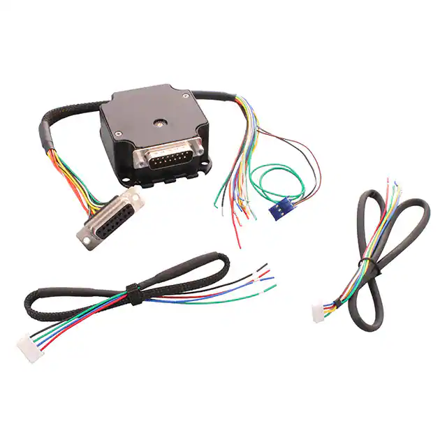
STMicroelectronics SPMD150STP
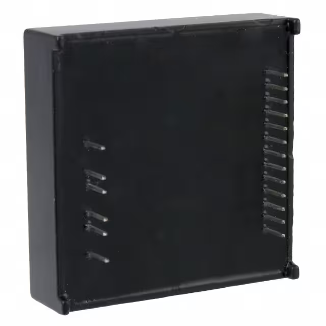
- Part No.:
- SPMD150STP
- Manufacturer:
- STMicroelectronics
- Category:
- Motor Driver Boards, Modules
- Package:
- Datasheet:
-
 SPMD150STP.pdf
- Description:
- STEPPER DRIVER 1.5A 10-42V LOAD
- Quantity:
- Payment:

- Shipping:

Inventory:3,669
Please send an inquiry. Send us your inquiry, and we will respond immediately.
Product details
Overview
SPMD150STP from STMicroelectronics is a fully integrated, metallic-cased stepper motor driver module for two-phase bipolar stepper motors, delivering 1.5 A average phase current at up to 42 V supply, supporting full/half-step and microstepping via TTL/CMOS logic interface and programmable current decay modes - deployed in industrial CNC positioning stages requiring robust, heatsink-free motion control.
For engineers reviewing the SPMD150STP datasheet, SPMD150STP pinout, SPMD150STP application, or SPMD150STP equivalent, key selection considerations include its chopper-controlled PWM current regulation, non-dissipative overcurrent protection, dual independent bridge timing (16 µs off-time), sealed metal package (50.8 × 50.8 × 14.7 mm), and -40°C to +85°C operating range.
Technical Context
The SPMD150STP integrates two independent MOSFET full-bridge power stages with intrinsic freewheeling diodes and 1 µs dead-time control to prevent cross-conduction. Each bridge features a constant off-time PWM current controller sensing phase current via external sense resistors, with reference inputs (VREFA/VREFB) scaling output current per IOUT = VREFx/0.192 A.
Logic-level inputs (CLOCK, CW/CCW, HALF/FULL, CONTROL, RESET, EN) interface directly to 3.3 V or 5 V microcontrollers, with internal pull-up/pull-down networks and open-collector–compatible EN pin. Decay mode (fast/slow) and stepping sequence (full/half/micro) are digitally selected, while thermal shutdown triggers at 165 °C junction temperature.
Key Specifications
| Parameter | Value and Actual Design Meaning |
|---|---|
| Supply Voltage (VS) | 10–42 V DC - supports wide-range industrial DC bus supplies without external regulation. |
| Output Current (Avg) | ±1.5 A per phase - sufficient for NEMA 17–23 stepper motors in closed-loop positioning systems. |
| Current Sensing Ref | VREF = 1.225 V ±1.2% - stable internal reference enabling precise current setting via external resistor divider or DAC. |
| Off-Time Setting | 16 µs typical (RCA/RCB) - fixed internal RC network allows predictable chopper frequency and current ripple control. |
| Logic Compatibility | TTL/CMOS - direct interfacing with STM32, PIC, or Arduino GPIO without level-shifting circuitry. |
| Thermal Shutdown | 165 °C junction - autonomous protection preserving motor and driver integrity during stall or overload. |
| Operating Temp | -40°C to +85°C case - validated for embedded motion control in unventilated enclosures. |
Pinout & Package
SPMD150STP uses a custom 19-pin through-hole metallic module package (50.8 × 50.8 × 14.7 mm), sealed and molded for IP65-equivalent environmental resilience. The metal case serves as thermal path and EMI shield, eliminating need for external heatsink or forced airflow.
| Pin/Terminal | Circuit Role | Design Meaning |
|---|---|---|
| 1 VSS | Logic supply input | Accepts 3.3 V or 5 V - powers internal logic and interfaces; internal 10 kΩ pull-ups referenced here. |
| 2 REF | Reference voltage output | 1.225 V ±1.2% - used to set phase current via external resistor dividers on VREFA/VREFB. |
| 3 RESET | State machine reset | Active-low synchronous reset to home state (State 1); internal 10 kΩ pull-up ensures safe default. |
| 4 CLOCK | Step command input | Rising-edge triggered - advances phase sequencer; min. 1 µs high/low pulse width required. |
| 5 CW/CCW | Direction control | High = clockwise rotation (per winding polarity); internal 10 kΩ pull-up prevents floating state. |
| 6 VREFA | Phase A/B current reference | Sets max current for Bridge A/B: IOUT = VREF/0.192 A; internal 100 kΩ pull-down + 470 pF filter. |
| 7 RCA | Bridge A off-time set | Configures PWM off-time (default 16 µs); parallel R/C adjusts timing for current ripple optimization. |
| 8 EN | Module enable | Active-high; open-collector recommended - disables outputs to high-Z for manual motor positioning. |
| 9 CONTROL | Decay mode select | High = slow decay (lower power loss); Low = fast decay (higher torque at speed); internal 10 kΩ pull-up. |
| 10 HALF/FULL | Stepping mode select | High = half-step (8 states/rev); Low = full-step (4 states/rev); determines excitation pattern sequence. |
| 11 VREFB | Phase C/D current reference | Independent current setting for Bridge C/D - enables true microstepping with variable current profiles. |
| 12 RCB | Bridge C/D off-time set | Dual independent timing control - allows asymmetric off-times for optimized torque/speed trade-offs. |
| 13 GND1 | Logic ground | Return path for VSS, REF, and all logic signals - isolated from power ground to reduce noise coupling. |
| 14 GND2 | Power ground | Return path for VS and motor phase currents - separate plane minimizes switching noise in logic domain. |
| 15 PHD | Phase D output | H-bridge output terminal for bipolar stepper winding D - rated for ±1.5 A continuous, 2.5 A peak. |
| 16 PHC | Phase C output | H-bridge output terminal for bipolar stepper winding C - complements PHD in dual-bridge configuration. |
| 17 PHB | Phase B output | H-bridge output terminal for bipolar stepper winding B - paired with PHA for two-phase drive. |
| 18 PHA | Phase A output | H-bridge output terminal for bipolar stepper winding A - primary excitation pair with PHB. |
| 19 VS | Power stage supply | 10–42 V input for motor and H-bridges - absolute max 50 V; requires local bulk capacitance per layout guidelines. |
Key Features
| Feature | Design Value |
|---|---|
| Non-dissipative overcurrent protection | Internally limits phase current to 4–7.1 A during short-circuit events without external shunt or power loss. |
| Programmable current decay mode | Selectable fast/slow decay via CONTROL pin - balances torque retention, power dissipation, and acoustic noise. |
| Dual independent PWM controllers | Separate VREFA/VREFB and RCA/RCB pins enable true microstepping with independent current profiling per phase pair. |
| Metallic sealed enclosure | 50.8 × 50.8 × 14.7 mm hermetically molded case - operates at full rating without heatsink or fan in -40°C to +85°C ambient. |
| Remote shutdown & thermal protection | EN pin enables safe motor coasting; junction shutdown at 165 °C prevents irreversible damage under sustained overload. |
Applications
| Industrial CNC Positioning | Automated Laboratory Equipment |
|---|---|
|
Use Scenario: Precision X-Y table movement in benchtop milling and engraving systems with real-time step command streaming. IC Role / Device Role / Timing Role: Dual-H-bridge stepper driver executing full/half-step sequences synchronized to microcontroller CLOCK pulses with sub-millisecond timing fidelity. Use Value: 1.5 A continuous current and 42 V headroom enable high-torque, low-vibration motion at speeds up to 50 kHz step rate without external current amplification. |
Use Scenario: Reagent dispensing arm in automated ELISA analyzers requiring repeatable 0.1° angular resolution and silent operation. IC Role / Device Role / Timing Role: Microstepping controller using variable VREFA/VREFB inputs from MCU DAC to generate sinusoidal current profiles across two phase pairs. Use Value: Independent bridge timing (RCA/RCB) and decay control suppress resonance and audible noise while maintaining position accuracy within ±0.05°. |
| Medical Imaging Stage Control | Factory Automation Indexers |
|
Use Scenario: CT gantry collimator alignment and PET detector calibration stages exposed to EMI-rich radiology environments. IC Role / Device Role / Timing Role: EMI-hardened motion controller with metallic shielding, isolated logic/power grounds (GND1/GND2), and non-dissipative fault protection. Use Value: Sealed metal package and thermal shutdown ensure uninterrupted operation during multi-hour imaging sessions without derating. |
Use Scenario: Rotary indexing table in packaging line with frequent start/stop cycles and ambient temperatures up to 75°C. IC Role / Device Role / Timing Role: Robust stepper interface accepting 24 V logic-compatible signals and driving NEMA 23 motors directly from PLC step/direction outputs. Use Value: TTL/CMOS compatibility, -40°C to +85°C rating, and remote EN shutdown allow integration into legacy control cabinets without signal conditioning. |
Availability
SPMD150STP is available at Aetrix Electronics and suitable for industrial CNC positioning, automated laboratory equipment, medical imaging stage control, and factory automation indexers requiring stable component supply, long-lifecycle support, and traceable sourcing.
Supply support for SPMD150STP includes scheduled delivery planning, volume procurement assistance, BOM continuity management, traceable sourcing, and lifecycle availability coordination for OEM customers, industrial embedded developers, connected-device designers, and electronics production programs.
Manufacturer
STMicroelectronics is a global semiconductor leader headquartered in Geneva, Switzerland, designing and manufacturing analog, mixed-signal, power, and microcontroller solutions for industrial, automotive, and consumer applications.
The SPMD150STP belongs to ST's motion control module family, engineered specifically for plug-and-play stepper motor actuation in space-constrained, thermally demanding industrial environments - emphasizing reliability, integration, and immunity to harsh electrical conditions.
FAQ
What is the maximum motor supply voltage supported by SPMD150STP?
The SPMD150STP supports a DC motor supply voltage (VS) from 10 V to 42 V, with an absolute maximum rating of 50 V. Operation above 42 V risks exceeding safe operating area limits and triggering overvoltage protection. Designers must use appropriate bulk capacitance and transient suppression on the VS rail per ST Application Note AN2822.
How is microstepping implemented on SPMD150STP?
Microstepping is achieved by independently modulating VREFA and VREFB with time-varying reference voltages (e.g., from MCU DAC outputs), while synchronizing CLOCK pulses. The internal PWM controllers adjust phase current magnitude per bridge, generating interpolated current waveforms between full-step positions - enabling up to 1/16 microstepping resolution depending on external control precision.
Does SPMD150STP require an external heat sink?
No. The SPMD150STP's metallic case is thermally optimized to dissipate heat directly into ambient air, allowing full 1.5 A operation from -40°C to +85°C case temperature without external heatsink or forced airflow. Thermal performance validation is documented in Section 4.7 of datasheet Doc ID 17160 Rev 1, including derating curves.
Can SPMD150STP drive unipolar stepper motors?
No. The SPMD150STP is designed exclusively for two-phase bipolar stepper motors with center-tapped or four-lead windings. Its dual full-bridge topology requires bidirectional current flow in each phase; unipolar motors lack the necessary winding configuration and would not achieve proper commutation or torque generation.
SPMD150STP Specifications
- Product attributes
- Attribute value
- Manufacturer:
- STMicroelectronics
- Series:
- EASY POWER™
- Packaging:
- Box
- Product Status:
- Obsolete
- Type:
- Module
- Motor Type:
- Stepper
- Control / Drive Type:
- Stepper, Bipolar
- Number of Motors:
- 1
- Voltage - Load:
- 10 ~ 42V
- Current - Output:
- 1.5A
- Wattage - Load:
- -
- Voltage - Supply:
- 3 ~ 5.25VDC
- Interface:
- Step / Direction
- Mounting Type:
- Through Hole
- Operating Temperature:
- -40°C ~ 85°C
- Features:
- -
- For Use With/Related Products:
- -
SPMD150STP FAQ
1.How can I place an order for SPMD150STP through Aetrix?
Please submit a Request for Quotation (RFQ) for SPMD150STP on Aetrix. Our sales agent will provide a competitive quotation and guide you through the order confirmation once you accept the terms.
2.Are the price and stock information for SPMD150STP reliable?
The price and inventory of SPMD150STP are updated periodically and may fluctuate due to market conditions. Stock and pricing data are typically refreshed every 24 hours. Quotation validity for SPMD150STP is usually 5 days.
3.What payment methods are accepted for SPMD150STP?
We accept Wire Transfer, PayPal, Credit Card, Western Union, MoneyGram, and Escrow for SPMD150STP transactions.
Note: Certain payment methods may incur a processing fee.
4.How is shipping managed for SPMD150STP?
SPMD150STP orders can be shipped via leading logistics carriers, including DHL, UPS, FedEx, TNT, or Registered Mail.
Once your SPMD150STP order is processed, you will receive an email with the shipment details and tracking number.
Note: Tracking information may take up to 24 hours to appear. Express delivery typically takes 3–5 business days.
5.How can I obtain technical support or documentation for SPMD150STP?
For technical support, including SPMD150STP datasheets, pinout diagrams, or application guidance, please contact our engineering support team. They can provide detailed documentation and assistance for your SPMD150STP requirements.
6.How does Aetrix verify that SPMD150STP is sourced from the original manufacturer or authorized distributors?
All SPMD150STP products on Aetrix are procured from qualified distributors and authorized channels. Our dedicated quality assurance team conducts strict verification, including traceability checks and, if necessary, third-party testing. This ensures that SPMD150STP meets industry standards.
7.What is the process for return or replacement of SPMD150STP?
All SPMD150STP units undergo pre-shipment inspection (PSI). If there is an issue with SPMD150STP, returns or replacements are accepted under the following conditions:
1.Quantity discrepancies, incorrect items, or visible external defects (such as breakage or corrosion), acknowledged by Aetrix.
2.The issue is reported within 90 days of delivery.
3.The SPMD150STP part is unused and in its original packaging.
Return procedure for SPMD150STP:
1.Submit a request within 90 days.
2.Obtain a Return Material Authorization (RMA) from Aetrix.
SPMD150STP Tags
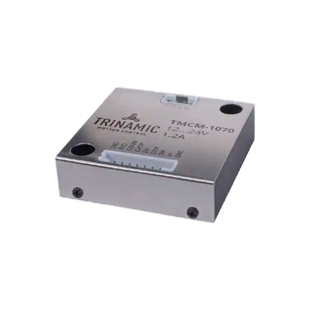
-
TMCM-1070
Analog Devices Inc./Maxim Integrated
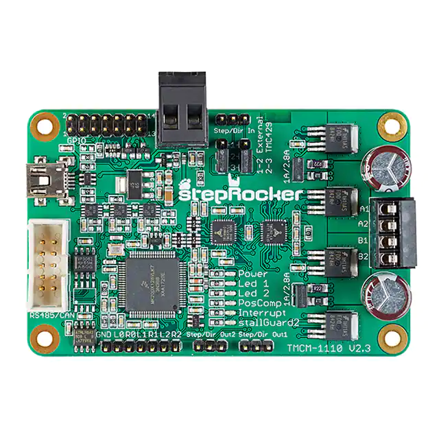
-
TMCM-1110-STEPROCKER
Analog Devices Inc./Maxim Integrated
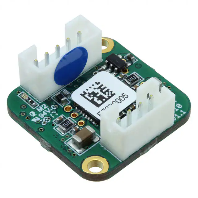
-
TMCM-1210
Analog Devices Inc./Maxim Integrated
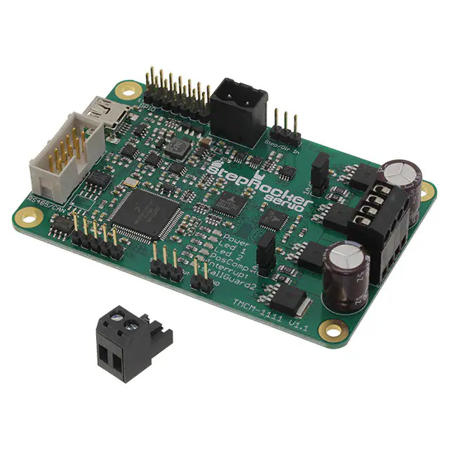
-
TMCM-1111 STEPROCKER
Analog Devices Inc./Maxim Integrated
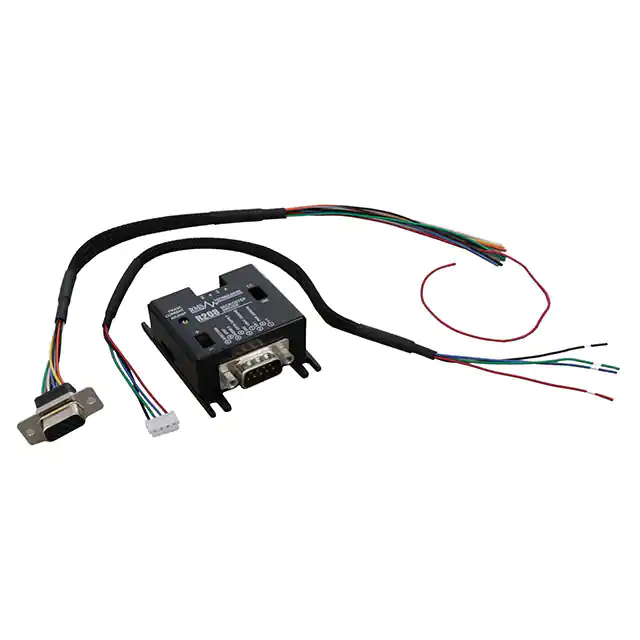
-
R208
Lin Engineering
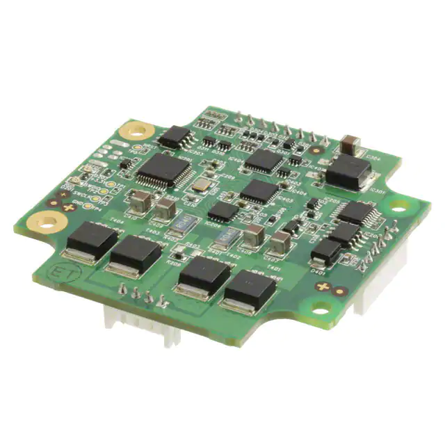
-
TMCM-1161
Analog Devices Inc./Maxim Integrated
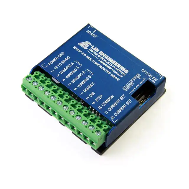
-
R701P-RO
Lin Engineering
-
TMCM-1633-CANOPEN
Analog Devices Inc./Maxim Integrated
-
TMCM-1316 STEPROCKER
Analog Devices Inc./Maxim Integrated
-
TMCM-3110-TMCL
Analog Devices Inc./Maxim Integrated
-
VZ.VTD2440K4
ebm-papst Inc.
-
R356
Lin Engineering
Tech Hub

A practical engineering and sourcing framework covering lifecycle verification, lifetime-buy calculations, replacement qualification, supplier checks and counterfeit-risk controls.

TTL and CMOS logic families differ in thresholds, loading, output drive, power and timing. This engineering guide compares 74HC and 74HCT, calculates noise margins and checks 3.3 V/5 V compatibility.

A practical engineering guide to 3.3V and 5V logic compatibility, input thresholds, resistor dividers, translator ICs, MOSFET level shifting, I2C pull-ups, timing limits and power-sequencing risks.

The 74HC595 uses push-pull logic outputs, while the TPIC6B595 uses 50 V open-drain DMOS sinks for higher-power loads. This guide compares timing, current limits, 3.3 V interfacing, load wiring, thermal…

The 74HC595 converts serial data into eight stable parallel outputs. This guide covers pin functions, shift and storage timing, OE and MR behavior, drive-current limits, cascading, voltage compatibilit…

A technical comparison of level-sensitive latches and edge-triggered flip-flops, covering timing windows, setup and hold limits, master–slave operation, time borrowing, race-through, HDL inference and…

A D latch stores one bit while Enable controls when data can pass. This reference covers gate-level operation, truth tables, transparency, setup and hold timing, LE versus OE, common ICs and practical …

An SR latch stores one bit through cross-coupled feedback. This engineering reference covers NOR and NAND implementations, truth tables, forbidden-state recovery, gated operation, switch debouncing, fa…

Latch circuits retain one bit through feedback. This technical reference covers SR and D latches, truth tables, transparency, timing limits, latch-versus-flip-flop behavior, applications and common log…

An engineering guide to LED driver operation, constant-current and constant-voltage outputs, linear and switching topologies, dimming, IC selection, calculations, replacement compatibility, and fault c…


