
 My Inquiry
 My Account


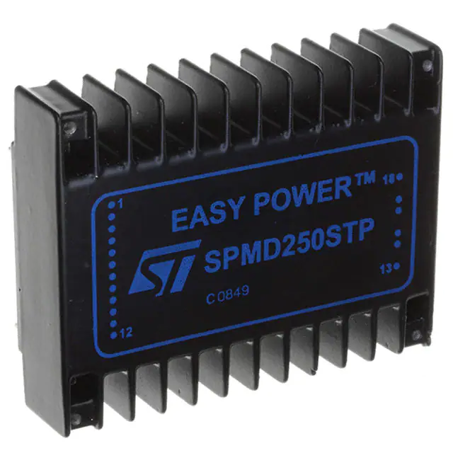
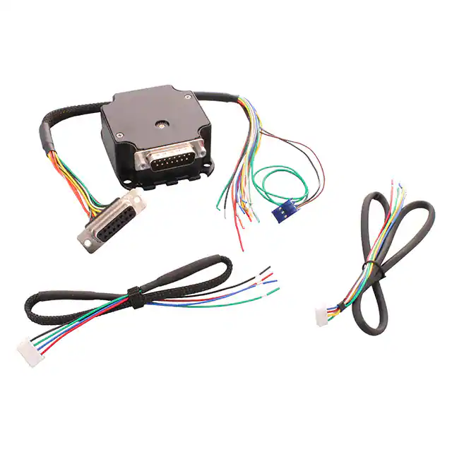
STMicroelectronics SPMD250STP
- Part No.:
- SPMD250STP
- Manufacturer:
- STMicroelectronics
- Category:
- Motor Driver Boards, Modules
- Package:
- Datasheet:
-
 SPMD250STP.pdf
- Description:
- STEPPER DRIVER 2.5A 12-40V LOAD
- Quantity:
- Payment:

- Shipping:

Inventory:3,231
Please send an inquiry. Send us your inquiry, and we will respond immediately.
Product details
Overview
SPMD250STP from STMicroelectronics is a 2.5 A bipolar stepper motor drive module with integrated Power MOSFET outputs, chopper-controlled phase current regulation, and on-board phase sequence generation for full/half-step operation. It operates from 12–40 V motor supply and 5 V logic supply, supports TTL/CMOS logic inputs, and delivers programmable chopper frequency (17 kHz default) and selectable slow/fast current decay - used in precision motion control systems requiring microprocessor-driven motor positioning without external sequencing logic.
For engineers reviewing the SPMD250STP datasheet, SPMD250STP pinout, SPMD250STP application, or SPMD250STP equivalent, key selection criteria include its 2.5 A continuous phase current rating, internal 3-bit gray-code counter for half-step generation, Sync pin synchronization capability for multi-motor systems, and latching short-circuit protection across all four power outputs (A/B/C/D).
Technical Context
The SPMD250STP integrates a fixed-frequency chopper controller (17 kHz nominal), dual PWM current regulators per winding, and combinational logic driving a 3-bit counter to generate eight-state gray-code sequences for half-step mode - with full-step modes derived by skipping alternate states based on the HALF/FULL pin state at mode entry. Its output stage uses discrete Power MOSFETs with source/sink saturation voltage ≤1.8 V at 2 A.
Logic-level signals (RESET, STEPCL, CW/CCW, ENABLE, HOME) interface directly to microcontrollers, while protection circuitry provides latching shutdown on overcurrent events (≥5 A limit), with recovery requiring ENABLE deactivation or 100 ms supply removal. Thermal resistance is 5 °C/W case-to-ambient, requiring heatsinking above ~10 W dissipation.
Key Specifications
| Parameter | Value and Actual Design Meaning |
|---|---|
| Phase current | 2.5 A continuous per winding - sets maximum torque output and thermal load under steady-state operation. |
| Supply voltage (VS) | 12–40 V DC - supports wide-range industrial motor supplies; absolute max 42 V prevents overvoltage damage. |
| Chopper frequency | 17 kHz (programmable via OSC pin) - determines PWM switching loss vs. audible noise trade-off; higher values reduce motor ripple but increase MOSFET switching loss. |
| Logic supply (VSS) | 5 V ±5% - powers internal logic and level shifters; must be sequenced before VS during power-up to avoid mispositioning. |
| Current decay mode | Selectable slow/fast via CONTROL pin - slow decay reduces power dissipation and EMI; fast decay improves high-speed torque response but requires external fast-recovery diodes. |
| Short-circuit protection | Latching type - disables outputs permanently until ENABLE is pulled low or supply is cycled; protects against shorts to GND, VS, or cross-phase faults. |
| Operating case temperature | –40 to +85 °C - defines safe junction temperature envelope; derating required above 10 W dissipation due to 5 °C/W thermal resistance. |
Pinout & Package
The SPMD250STP is housed in a metal-can, through-hole mounted power module with isolated logic and power grounds (GND1 and GND2), designed for direct PCB mounting with heatsinking via the case. Pin layout follows a 18-pin dual-row configuration with dedicated motor phase outputs (A/B/C/D), logic I/O, and supply terminals.
| Pin/Terminal | Circuit Role | Design Meaning |
|---|---|---|
| 1 GND1 | Logic ground return | Reference for all logic signals and VSS; must be connected separately from power ground to minimize noise coupling. |
| 2 Sync | Oscillator sync I/O | Enables multi-module synchronization; can accept external clock or drive other modules' Sync pins to eliminate beat frequencies. |
| 3 Reset | Asynchronous reset input | Active-low signal forcing internal counter to home state (ABCD = 0101); used for system initialization or error recovery. |
| 4 Half/Full | Drive mode select | High/unconnected enables half-step (8-step/rev); low selects full-step (4-step/rev), with wave or normal mode determined by counter state. |
| 5 Home | Home position indicator | Open-collector output active-high when counter is at initial state; intended for AND-ing with mechanical/optical home sensor. |
| 6 Stepcl | Step clock input | Rising-edge-triggered step advance; timing requires ≥0.5 µs pulse width, ≥1 µs setup/hold relative to RESET. |
| 7 CW/CCW | Direction control | High/unconnected selects clockwise rotation; actual direction depends on motor winding polarity and connection. |
| 8 Oscillator | Chopper frequency adjust | Connect resistor to VSS to increase fc; capacitor to GND1 to decrease fc; grounded when externally synchronized. |
| 9 Ioset | Phase current programming | Resistor to GND1 or VSS adjusts factory-set 2 A current; max 2.5 A to prevent permanent damage. |
| 10 Control | Decay mode select | High/unconnected enables slow decay (lower heat/noise); low enables fast decay (better high-speed torque). |
| 11 Enable | Module enable | Active-high; must be LOW at power-up/down; floats outputs when LOW for manual motor positioning. |
| 12 Vss | 5 V logic supply | Must not exceed 7 V; powers internal logic and level shifters; requires proper sequencing with VS. |
| 13 GND2 | Power ground return | Return path for motor current and power stage; must be connected to case mounting point for EMI shielding. |
| 14–17 A/B/C/D | Motor phase outputs | Four Power MOSFET outputs driving two bipolar windings (A-B and C-D); each rated for 2.5 A continuous. |
| 18 Vs | Motor supply input | 12–40 V DC input for motor windings; includes internal decoupling capacitor; requires external 470 µF low-ESR bulk cap. |
Key Features
| Feature | Design Value |
|---|---|
| Integrated phase sequence generator | 3-bit gray-code counter + combinational logic eliminates need for external microcontroller step sequencing in half/full-step modes. |
| Programmable chopper frequency | 17 kHz base frequency adjustable via external R/C on OSC pin - enables optimization for motor inductance, noise, and efficiency. |
| Selectably slow/fast current decay | CONTROL pin configures recirculation path - slow decay minimizes heat and EMI; fast decay maintains torque at higher speeds. |
| Synchronization for multi-motor systems | SYNC pin allows precise chopper timing alignment across multiple SPMD250STP units - eliminates audible beat interference and improves system timing coherence. |
| Latching short-circuit protection | Shuts down all outputs on overcurrent (>5 A) and holds fault state until ENABLE is cycled - prevents cascading failure in multi-winding systems. |
Applications
| Industrial CNC Positioning | Medical Infusion Pump Actuation |
|---|---|
|
Use Scenario: Precise linear displacement of tool heads in benchtop CNC mills using NEMA 17 bipolar stepper motors. IC Role / Device Role / Timing Role: Direct microcontroller interface to motor windings; generates internal phase sequences and regulates current via chopper PWM at 17 kHz. Use Value: Eliminates external H-bridge drivers and step-sequence firmware, reducing BOM count and software overhead while maintaining 2.5 A peak torque at 200 steps/rev resolution. |
Use Scenario: Controlled syringe plunger advancement in portable infusion pumps requiring silent, repeatable microstep positioning. IC Role / Device Role / Timing Role: Motor driver with slow-decay current recirculation and programmable chopper frequency to suppress audible noise below 20 kHz. Use Value: Enables quiet operation (<35 dB) at therapeutic flow rates by selecting 12 kHz chopper frequency and slow decay, avoiding resonance in plastic pump housings. |
| Automated Laboratory Sample Handler | Print Head Carriage Control |
|
Use Scenario: Multi-axis XYZ sample positioning in automated ELISA plate readers with synchronized motion across three SPMD250STP modules. IC Role / Device Role / Timing Role: Synchronized stepper driver using shared SYNC signal to align chopper clocks and eliminate beat frequencies between axes. Use Value: Ensures jitter-free coordinated movement during optical scanning, preventing image smear by eliminating 1–5 kHz intermodulation artifacts from unsynchronized PWM. |
Use Scenario: Bidirectional carriage movement in thermal inkjet printers with rapid start/stop cycles and positional repeatability <±0.05 mm. IC Role / Device Role / Timing Role: High-speed step response driver with fast-decay mode and 200 ns minimum STEPCL pulse width support. Use Value: Achieves 15 ms acceleration to 200 mm/s via fast decay and 2.5 A phase current, enabling 1200 dpi print resolution with sub-pixel positioning accuracy. |
Equivalent & Alternatives
The following parts are listed as comparable options for similar bipolar stepper motor drive applications.
| Alternative Part | Technical Difference | Application Difference | Selection Advice |
|---|---|---|---|
| TB6600HG | Higher 4.5 A phase current, external current sense resistors, no integrated sequence generator - requires external step/direction signals and microcontroller-based sequencing. | Used where higher torque is needed and microcontroller resources exist for full-step control; lacks SPMD250STP's half-step auto-generation and Sync pin. | Select when scaling to larger NEMA 23 motors and existing firmware already handles sequencing; avoid if minimizing MCU overhead is critical. |
| LV8729V | Lower 1.5 A rating, integrated indexer with microstepping (up to 32x), SPI interface, no latching protection - relies on external watchdog or host recovery. | Preferred for compact embedded systems needing microstepping and digital configuration; lacks SPMD250STP's ruggedized metal-can package and multi-module Sync. | Select for space-constrained designs requiring >1.8° resolution and digital tuning; avoid in industrial environments with high EMI or need for hardware-fault resilience. |
Compared with TB6600HG and LV8729V, the SPMD250STP uniquely combines on-chip half/full-step sequence generation, metal-can EMI shielding, latching fault protection, and hardware Sync - making it optimal for robust, low-software-overhead motion control where deterministic startup and multi-axis coherence are essential.
Availability
SPMD250STP is available at Aetrix Electronics and suitable for industrial CNC positioning, medical infusion pump actuation, automated laboratory sample handling, and print head carriage control requiring stable component supply and long-term design continuity.
Supply support for SPMD250STP includes scheduled delivery planning, volume procurement assistance, BOM continuity management, traceable sourcing, and lifecycle availability coordination for OEM customers, industrial embedded developers, connected-device designers, and electronics production programs.
Manufacturer
STMicroelectronics is a global semiconductor leader headquartered in Geneva, specializing in power management, motion control, and automotive-grade ICs with broad industrial qualification.
The SPMD250STP belongs to ST's legacy power module family designed for standalone, microcontroller-offloaded stepper motor control in harsh industrial and medical environments - emphasizing hardware reliability over digital configurability.
FAQ
What is the maximum allowable phase current for the SPMD250STP, and how is it set?
The SPMD250STP is factory-set to 2 A per phase and rated for up to 2.5 A continuous. Current is adjusted using a resistor between Ioset (pin 9) and GND1 or VSS: connecting to GND1 lowers current, to VSS raises it. Exceeding 2.5 A risks permanent damage due to thermal overload, as confirmed in Section 9.8 of the datasheet.
How does the SPMD250STP handle motor overcurrent conditions?
It features latching overcurrent protection that disables all four power outputs when phase current exceeds 5 A. Recovery requires pulling ENABLE (pin 11) low or removing power for ≥100 ms. This behavior is hardware-enforced and independent of microcontroller intervention, ensuring fail-safe shutdown in wiring faults or stalled motor conditions.
Can multiple SPMD250STP modules be synchronized, and what is required?
Yes - connect all SYNC pins (pin 2) together to align chopper oscillator timing across modules. When externally synchronized, the OSC pin (pin 8) must be grounded. This eliminates audible beat frequencies and ensures deterministic timing in multi-axis systems, as detailed in Section 10 of the datasheet.
What thermal management is required for continuous 2.5 A operation?
At 2.5 A and 24 V, typical power dissipation exceeds 10 W. With a case-to-ambient thermal resistance of 5 °C/W, surface temperature rises ~50 °C above ambient - requiring a heatsink or forced airflow to maintain case temperature ≤85 °C. Derating curves in Figure 16 confirm this threshold applies across the full operating range.
SPMD250STP Specifications
- Product attributes
- Attribute value
- Manufacturer:
- STMicroelectronics
- Series:
- EASY POWER™
- Packaging:
- Bulk
- Product Status:
- Obsolete
- Type:
- Module
- Motor Type:
- Stepper
- Control / Drive Type:
- Stepper, Bipolar
- Number of Motors:
- 1
- Voltage - Load:
- 12 ~ 40V
- Current - Output:
- 2.5A
- Wattage - Load:
- -
- Voltage - Supply:
- 5VDC
- Interface:
- Step / Direction
- Mounting Type:
- Through Hole
- Operating Temperature:
- -40°C ~ 85°C
- Features:
- -
- For Use With/Related Products:
- -
SPMD250STP FAQ
1.How can I place an order for SPMD250STP through Aetrix?
Please submit a Request for Quotation (RFQ) for SPMD250STP on Aetrix. Our sales agent will provide a competitive quotation and guide you through the order confirmation once you accept the terms.
2.Are the price and stock information for SPMD250STP reliable?
The price and inventory of SPMD250STP are updated periodically and may fluctuate due to market conditions. Stock and pricing data are typically refreshed every 24 hours. Quotation validity for SPMD250STP is usually 5 days.
3.What payment methods are accepted for SPMD250STP?
We accept Wire Transfer, PayPal, Credit Card, Western Union, MoneyGram, and Escrow for SPMD250STP transactions.
Note: Certain payment methods may incur a processing fee.
4.How is shipping managed for SPMD250STP?
SPMD250STP orders can be shipped via leading logistics carriers, including DHL, UPS, FedEx, TNT, or Registered Mail.
Once your SPMD250STP order is processed, you will receive an email with the shipment details and tracking number.
Note: Tracking information may take up to 24 hours to appear. Express delivery typically takes 3–5 business days.
5.How can I obtain technical support or documentation for SPMD250STP?
For technical support, including SPMD250STP datasheets, pinout diagrams, or application guidance, please contact our engineering support team. They can provide detailed documentation and assistance for your SPMD250STP requirements.
6.How does Aetrix verify that SPMD250STP is sourced from the original manufacturer or authorized distributors?
All SPMD250STP products on Aetrix are procured from qualified distributors and authorized channels. Our dedicated quality assurance team conducts strict verification, including traceability checks and, if necessary, third-party testing. This ensures that SPMD250STP meets industry standards.
7.What is the process for return or replacement of SPMD250STP?
All SPMD250STP units undergo pre-shipment inspection (PSI). If there is an issue with SPMD250STP, returns or replacements are accepted under the following conditions:
1.Quantity discrepancies, incorrect items, or visible external defects (such as breakage or corrosion), acknowledged by Aetrix.
2.The issue is reported within 90 days of delivery.
3.The SPMD250STP part is unused and in its original packaging.
Return procedure for SPMD250STP:
1.Submit a request within 90 days.
2.Obtain a Return Material Authorization (RMA) from Aetrix.
SPMD250STP Tags
-
TMCM-1070
Analog Devices Inc./Maxim Integrated
-
TMCM-1110-STEPROCKER
Analog Devices Inc./Maxim Integrated
-
TMCM-1210
Analog Devices Inc./Maxim Integrated
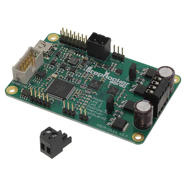
-
TMCM-1111 STEPROCKER
Analog Devices Inc./Maxim Integrated
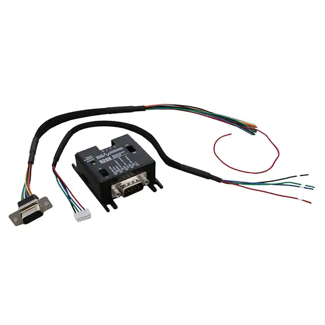
-
R208
Lin Engineering
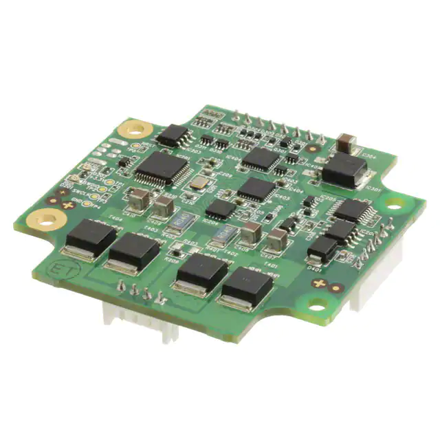
-
TMCM-1161
Analog Devices Inc./Maxim Integrated
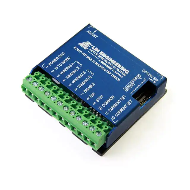
-
R701P-RO
Lin Engineering
-
TMCM-1633-CANOPEN
Analog Devices Inc./Maxim Integrated
-
TMCM-1316 STEPROCKER
Analog Devices Inc./Maxim Integrated
-
TMCM-3110-TMCL
Analog Devices Inc./Maxim Integrated
-
VZ.VTD2440K4
ebm-papst Inc.
-
R356
Lin Engineering
Tech Hub

A practical engineering and sourcing framework covering lifecycle verification, lifetime-buy calculations, replacement qualification, supplier checks and counterfeit-risk controls.

TTL and CMOS logic families differ in thresholds, loading, output drive, power and timing. This engineering guide compares 74HC and 74HCT, calculates noise margins and checks 3.3 V/5 V compatibility.

A practical engineering guide to 3.3V and 5V logic compatibility, input thresholds, resistor dividers, translator ICs, MOSFET level shifting, I2C pull-ups, timing limits and power-sequencing risks.

The 74HC595 uses push-pull logic outputs, while the TPIC6B595 uses 50 V open-drain DMOS sinks for higher-power loads. This guide compares timing, current limits, 3.3 V interfacing, load wiring, thermal…

The 74HC595 converts serial data into eight stable parallel outputs. This guide covers pin functions, shift and storage timing, OE and MR behavior, drive-current limits, cascading, voltage compatibilit…

A technical comparison of level-sensitive latches and edge-triggered flip-flops, covering timing windows, setup and hold limits, master–slave operation, time borrowing, race-through, HDL inference and…

A D latch stores one bit while Enable controls when data can pass. This reference covers gate-level operation, truth tables, transparency, setup and hold timing, LE versus OE, common ICs and practical …

An SR latch stores one bit through cross-coupled feedback. This engineering reference covers NOR and NAND implementations, truth tables, forbidden-state recovery, gated operation, switch debouncing, fa…

Latch circuits retain one bit through feedback. This technical reference covers SR and D latches, truth tables, transparency, timing limits, latch-versus-flip-flop behavior, applications and common log…

An engineering guide to LED driver operation, constant-current and constant-voltage outputs, linear and switching topologies, dimming, IC selection, calculations, replacement compatibility, and fault c…


