
 My Inquiry
 My Account


Microchip Technology SST39VF802C-70-4I-EKE-T
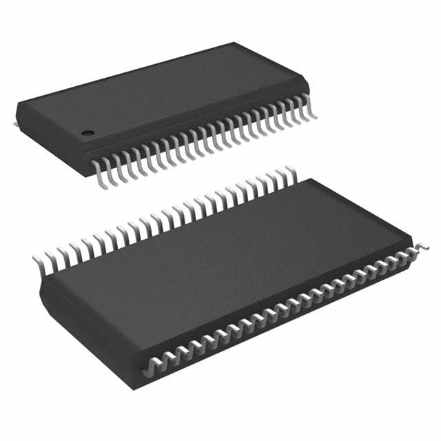
- Part No.:
- SST39VF802C-70-4I-EKE-T
- Manufacturer:
- Microchip Technology
- Category:
- Memory
- Package:
- 48-TFSOP (0.724", 18.40mm Width)
- Datasheet:
-
 SST39VF802C-70-4I-EKE-T.pdf
- Description:
- IC FLASH 8MBIT PARALLEL 48TSOP
- Quantity:
- Payment:

- Shipping:

Inventory:4,230
Please send an inquiry. Send us your inquiry, and we will respond immediately.
Product details
Overview
SST39VF802C-70-4I-EKE-T from Microchip Technology is a 8 Mbit (512K × 16) CMOS Multi-Purpose Flash Plus memory IC with 70 ns read access time, single 2.7–3.6V supply operation, and top-boot block protection. It delivers 100,000 program/erase cycles, >100 years data retention, and supports sector/block/chip erase in embedded firmware storage applications.
For engineers reviewing the SST39VF802C-70-4I-EKE-T datasheet, SST39VF802C-70-4I-EKE-T pinout, SST39VF802C-70-4I-EKE-T application, or SST39VF802C-70-4I-EKE-T equivalent, this page provides verified technical context, JEDEC-compliant x16 interface details, boot-block protection mapping, SuperFlash® endurance metrics, and real-world design implications for firmware update systems.
Technical Context
The SST39VF802C-70-4I-EKE-T implements SST's proprietary SuperFlash® technology with split-gate cells and thick-oxide tunneling injectors, enabling fixed erase/program times independent of cycle count. Its JEDEC-standard x16 parallel interface includes dedicated WP#, RST#, and open-drain RY/BY# for hardware status signaling.
It supports three software-controlled erase granularities-uniform 2 KWord sectors, flexible blocks (one 8-, two 4-, one 16-, fifteen 32-KWord), and full-chip erase-and features Erase-Suspend/Resume for concurrent read/program during active erase. The device uses toggle-bit (DQ6/DQ2) and Data# Polling (DQ7) for end-of-write detection without external timing dependencies.
Key Specifications
| Parameter | Value and Actual Design Meaning |
|---|---|
| Memory Density | 8 Mbit (512K × 16), providing 1 MB of nonvolatile storage for firmware images or configuration data. |
| Read Access Time | 70 ns - enables direct execution from flash (XIP) in 5 MHz bus systems with no wait states. |
| Supply Voltage | 2.7–3.6V - compatible with 3.3V logic domains and tolerant of brown-out conditions down to 2.7V. |
| Endurance | 100,000 program/erase cycles - supports field firmware updates over 10+ years in industrial controllers. |
| Data Retention | >100 years - ensures long-term reliability in unpowered storage for medical or aerospace black-box logging. |
| Block Protection | Top 8 KWord (7E000H–7FFFFH) hardware-protected via WP# - secures bootloader code against accidental overwrite. |
| Power Consumption | 5 mA active / 3 µA standby - reduces system-level power budget in battery-backed IoT gateways. |
Pinout & Package
Package: 48-lead TSOP (12 mm × 20 mm), RoHS-compliant, standard JEDEC x16 memory footprint.
| Pin/Terminal | Circuit Role | Design Meaning |
|---|---|---|
| A0–A18 | Address Inputs | 19-bit address bus supporting full 512K-word addressing; AMS = A18 for sector/block selection. |
| DQ0–DQ15 | Data I/O | 16-bit bidirectional data bus with internal latching; tri-stated when CE# or OE# high. |
| CE# | Chip Enable | Active-low chip select; device enters standby (3 µA) when high, enabling multi-chip memory expansion. |
| OE# | Output Enable | Active-low output gate; controls data bus drive without affecting internal state or power mode. |
| WE# | Write Enable | Active-low write strobe; latches address/data on falling/rising edges per JEDEC command sequences. |
| WP# | Write Protect | Active-low hardware lock for top 8 KWord boot block; floating = internally pulled high (unprotected). |
| RST# | Reset | Active-low hardware reset; terminates ongoing erase/program and forces return to read mode within TRP. |
| RY/BY# | Ready/Busy# | Open-drain status indicator; requires external 10–100 kΩ pull-up; low = busy, high = ready for next command. |
| VDD / VSS | Power / Ground | Single 2.7–3.6V supply; dual VSS pins reduce noise coupling in high-speed read cycles. |
| NC | No Connect | Unbonded pins (e.g., A13, A9 in TSOP); must remain unconnected per datasheet layout guidance. |
Key Features
| Feature | Design Value |
|---|---|
| SuperFlash® Technology | Split-gate cell architecture delivers fixed 18 ms sector/block erase and 7 µs word-program times across full lifecycle. |
| Erase-Suspend/Resume | Allows real-time read access to non-suspended sectors during active erase, enabling background firmware validation. |
| Hardware Block Protection | Top 8 KWord boot block (7E000H–7FFFFH) locked by WP# signal - prevents corruption of critical bootloader code. |
| Security ID Space | Factory-programmed 128-bit ID + 128-word user space, programmable via dedicated command sequence and lockable post-configuration. |
| CFI Compliance | Supports Common Flash Interface query mode (98H command) for automatic driver detection and runtime parameter extraction. |
Applications
| Firmware Storage in Industrial PLCs | Bootloader Memory in Network Routers |
|---|---|
|
Use Scenario: Storing field-upgradable firmware images and configuration tables in programmable logic controllers operating in harsh factory environments. IC Role / Device Role / Timing Role: Nonvolatile program memory mapped into CPU address space; executes XIP with 70 ns access enabling deterministic scan-cycle timing. Use Value: Top-boot hardware protection ensures bootloader integrity during remote firmware updates, eliminating risk of bricking due to power loss mid-update. |
Use Scenario: Holding primary bootloader and fail-safe recovery image in enterprise-grade routers requiring secure, reliable boot chain initialization. IC Role / Device Role / Timing Role: Boot memory accessed at power-on reset; RY/BY# pin synchronizes CPU fetch with flash readiness, avoiding race conditions. Use Value: 100,000-cycle endurance supports frequent security patch deployments over 10+ year product lifecycles without replacement. |
| Configuration Storage in Medical Imaging Systems | FPGA Bitstream Storage in Test Equipment |
|
Use Scenario: Retaining calibration coefficients, user preferences, and regulatory compliance settings across power cycles in MRI and CT scanner control units. IC Role / Device Role / Timing Role: Configuration memory accessed via memory-mapped I/O; Auto Low Power mode reduces idle current to 3 µA during standby intervals. Use Value: >100-year data retention guarantees calibration persistence through equipment decommissioning and long-term archival requirements. |
Use Scenario: Storing FPGA configuration bitstreams for reconfigurable digital signal processing modules in automated test equipment. IC Role / Device Role / Timing Role: Parallel x16 interface enables fast bitstream loading; sector-erase capability allows selective reprogramming of partial configurations. Use Value: Uniform 2 KWord sectors permit atomic updates of DSP firmware segments without erasing entire FPGA configuration space. |
Equivalent & Alternatives
The following parts are listed as comparable options for similar parallel NOR flash memory applications.
| Alternative Part | Technical Difference | Application Difference | Selection Advice |
|---|---|---|---|
| MX29LV800CTTI-70G | 8 Mbit (512K × 16), 70 ns, 3.0–3.6V supply; lacks RST# pin and Erase-Suspend feature. | Requires external reset management; unsuitable for systems needing in-erase read capability. | Select when cost sensitivity outweighs need for suspend/resume and hardware reset integration. |
| S29GL064N90TFIR20 | 64 Mbit (4M × 16), 90 ns, 2.7–3.6V; includes CFI but no Security ID; different block architecture (64 KWord uniform sectors). | Higher density but slower access; incompatible boot-block layout and erase granularity for SST39VF802C-70-4I-EKE-T migration. | Choose only for new designs requiring >8 Mbit capacity and where 90 ns latency is acceptable. |
Compared with MX29LV800CTTI-70G and S29GL064N90TFIR20, the SST39VF802C-70-4I-EKE-T uniquely combines top-boot hardware protection, Erase-Suspend, and integrated RST# in an 8 Mbit x16 package - making it optimal for safety-critical firmware storage where bootloader integrity and real-time operational flexibility are mandatory.
Availability
SST39VF802C-70-4I-EKE-T is available at Aetrix Electronics and suitable for industrial automation, network infrastructure, medical diagnostics, and test equipment requiring stable component supply with guaranteed long-term availability.
Supply support for SST39VF802C-70-4I-EKE-T includes scheduled delivery planning, volume procurement assistance, BOM continuity management, traceable sourcing, and lifecycle availability coordination for OEM customers, industrial embedded developers, connected-device designers, and electronics production programs.
Manufacturer
Microchip Technology acquired Silicon Storage Technology (SST) in 2010 and now manufactures, supports, and extends the SuperFlash® portfolio for embedded nonvolatile memory applications.
The SST39VF802C-70-4I-EKE-T belongs to the Multi-Purpose Flash Plus (MPF+) family, designed specifically for cost-sensitive, high-reliability firmware and configuration storage in resource-constrained microcontroller-based systems.
FAQ
What is the boot block configuration of the SST39VF802C-70-4I-EKE-T?
The SST39VF802C-70-4I-EKE-T implements top-boot block protection covering the 8 KWord address range 7E000H–7FFFFH. This region is hardware-locked when WP# is driven low, safeguarding bootloader code from accidental erase or program operations. Unlike the SST39VF801C variant, the SST39VF802C-70-4I-EKE-T does not protect the bottom block.
Does the SST39VF802C-70-4I-EKE-T require an external VPP voltage?
No, the SST39VF802C-70-4I-EKE-T does not require an external VPP voltage. It generates all necessary high-voltage programming pulses internally using its 2.7–3.6V VDD supply. This eliminates the need for auxiliary power rails and simplifies PCB design compared to older flash technologies.
How is end-of-write detection implemented in the SST39VF802C-70-4I-EKE-T?
The SST39VF802C-70-4I-EKE-T supports three end-of-write detection methods: Toggle Bit (DQ6 toggles during operation, stops when complete), Data# Polling (DQ7 complements data during program, returns true value on completion), and Ready/Busy# (RY/BY# open-drain pin pulled low during operation). All are usable concurrently and require no external timing components.
Can the SST39VF802C-70-4I-EKE-T be used in place of the SST39VF801C?
No - the SST39VF802C-70-4I-EKE-T and SST39VF801C are not functionally interchangeable due to opposite boot block configurations: SST39VF802C-70-4I-EKE-T protects the top 8 KWord (7E000H–7FFFFH), while SST39VF801C protects the bottom 8 KWord (00000H–01FFFH). Software and hardware protection schemes must be redesigned for substitution.
What package type is used in the SST39VF802C-70-4I-EKE-T part number suffix?
The "EKE" suffix in SST39VF802C-70-4I-EKE-T denotes the 48-lead TSOP (Thin Small Outline Package) with 12 mm × 20 mm body size and standard JEDEC pinout. This package is lead-free (RoHS-compliant) and rated for industrial temperature range (–40°C to +85°C), indicated by the "I" in the suffix.
SST39VF802C-70-4I-EKE-T Specifications
- Product attributes
- Attribute value
- Manufacturer:
- Microchip Technology
- Series:
- SST39 MPF™
- Package/Case:
- 48-TFSOP (0.724", 18.40mm Width)
- Packaging:
- Tape & Reel (TR)
- Product Status:
- Active
- Programmable:
- Verified
- Memory Type:
- Non-Volatile
- Memory Format:
- FLASH
- Technology:
- FLASH
- Memory Size:
- 8Mbit
- Memory Organization:
- 512K x 16
- Memory Interface:
- Parallel
- Clock Frequency:
- -
- Write Cycle Time - Word, Page:
- 10µs
- Access Time:
- 70 ns
- Voltage - Supply:
- 2.7V ~ 3.6V
- Operating Temperature:
- -40°C ~ 85°C (TA)
- Grade:
- -
- Qualification:
- -
- Mounting Type:
- Surface Mount
- Supplier Device Package:
- 48-TSOP
SST39VF802C-70-4I-EKE-T FAQ
1.How can I place an order for SST39VF802C-70-4I-EKE-T through Aetrix?
Please submit a Request for Quotation (RFQ) for SST39VF802C-70-4I-EKE-T on Aetrix. Our sales agent will provide a competitive quotation and guide you through the order confirmation once you accept the terms.
2.Are the price and stock information for SST39VF802C-70-4I-EKE-T reliable?
The price and inventory of SST39VF802C-70-4I-EKE-T are updated periodically and may fluctuate due to market conditions. Stock and pricing data are typically refreshed every 24 hours. Quotation validity for SST39VF802C-70-4I-EKE-T is usually 5 days.
3.What payment methods are accepted for SST39VF802C-70-4I-EKE-T?
We accept Wire Transfer, PayPal, Credit Card, Western Union, MoneyGram, and Escrow for SST39VF802C-70-4I-EKE-T transactions.
Note: Certain payment methods may incur a processing fee.
4.How is shipping managed for SST39VF802C-70-4I-EKE-T?
SST39VF802C-70-4I-EKE-T orders can be shipped via leading logistics carriers, including DHL, UPS, FedEx, TNT, or Registered Mail.
Once your SST39VF802C-70-4I-EKE-T order is processed, you will receive an email with the shipment details and tracking number.
Note: Tracking information may take up to 24 hours to appear. Express delivery typically takes 3–5 business days.
5.How can I obtain technical support or documentation for SST39VF802C-70-4I-EKE-T?
For technical support, including SST39VF802C-70-4I-EKE-T datasheets, pinout diagrams, or application guidance, please contact our engineering support team. They can provide detailed documentation and assistance for your SST39VF802C-70-4I-EKE-T requirements.
6.How does Aetrix verify that SST39VF802C-70-4I-EKE-T is sourced from the original manufacturer or authorized distributors?
All SST39VF802C-70-4I-EKE-T products on Aetrix are procured from qualified distributors and authorized channels. Our dedicated quality assurance team conducts strict verification, including traceability checks and, if necessary, third-party testing. This ensures that SST39VF802C-70-4I-EKE-T meets industry standards.
7.What is the process for return or replacement of SST39VF802C-70-4I-EKE-T?
All SST39VF802C-70-4I-EKE-T units undergo pre-shipment inspection (PSI). If there is an issue with SST39VF802C-70-4I-EKE-T, returns or replacements are accepted under the following conditions:
1.Quantity discrepancies, incorrect items, or visible external defects (such as breakage or corrosion), acknowledged by Aetrix.
2.The issue is reported within 90 days of delivery.
3.The SST39VF802C-70-4I-EKE-T part is unused and in its original packaging.
Return procedure for SST39VF802C-70-4I-EKE-T:
1.Submit a request within 90 days.
2.Obtain a Return Material Authorization (RMA) from Aetrix.
SST39VF802C-70-4I-EKE-T Tags

-
M24C02-WMN6TP
STMicroelectronics

-
AT24C02C-XHM-T
Microchip Technology

-
AT21CS01-STUM10-T
Microchip Technology

-
AT24C02C-SSHM-T
Microchip Technology

-
24LC01BT-I/OT
Microchip Technology

-
M24C02-FMC6TG
STMicroelectronics
-
AT24CS02-SSHM-T
Microchip Technology

-
93LC46BT-I/OT
Microchip Technology
-
AT24C04C-SSHM-T
Microchip Technology

-
24LC01BT-I/SN
Microchip Technology
-
24AA02UIDT-I/OT
Microchip Technology

-
AT24C08C-STUM-T
Microchip Technology
Tech Hub

TTL and CMOS logic families differ in thresholds, loading, output drive, power and timing. This engineering guide compares 74HC and 74HCT, calculates noise margins and checks 3.3 V/5 V compatibility.

A practical engineering guide to 3.3V and 5V logic compatibility, input thresholds, resistor dividers, translator ICs, MOSFET level shifting, I2C pull-ups, timing limits and power-sequencing risks.

The 74HC595 uses push-pull logic outputs, while the TPIC6B595 uses 50 V open-drain DMOS sinks for higher-power loads. This guide compares timing, current limits, 3.3 V interfacing, load wiring, thermal…

The 74HC595 converts serial data into eight stable parallel outputs. This guide covers pin functions, shift and storage timing, OE and MR behavior, drive-current limits, cascading, voltage compatibilit…

A technical comparison of level-sensitive latches and edge-triggered flip-flops, covering timing windows, setup and hold limits, master–slave operation, time borrowing, race-through, HDL inference and…

A D latch stores one bit while Enable controls when data can pass. This reference covers gate-level operation, truth tables, transparency, setup and hold timing, LE versus OE, common ICs and practical …

An SR latch stores one bit through cross-coupled feedback. This engineering reference covers NOR and NAND implementations, truth tables, forbidden-state recovery, gated operation, switch debouncing, fa…

Latch circuits retain one bit through feedback. This technical reference covers SR and D latches, truth tables, transparency, timing limits, latch-versus-flip-flop behavior, applications and common log…

An engineering guide to LED driver operation, constant-current and constant-voltage outputs, linear and switching topologies, dimming, IC selection, calculations, replacement compatibility, and fault c…

Operational amplifier guide covering op amp basics, feedback, ideal vs real op amps, common configurations, buffer circuits, offset, bias current, gain-bandwidth, slew rate, rail-to-rail limits and sel…


