
 My Inquiry
 My Account


STMicroelectronics ST26C32ABN
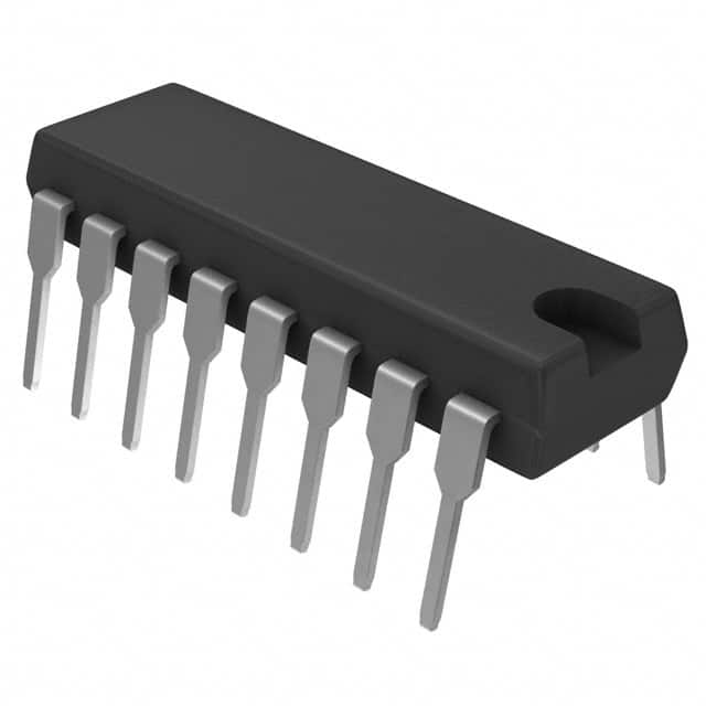
- Part No.:
- ST26C32ABN
- Manufacturer:
- STMicroelectronics
- Category:
- Drivers, Receivers, Transceivers
- Package:
- 16-DIP (0.300", 7.62mm)
- Datasheet:
-
 ST26C32ABN.pdf
- Description:
- IC TRANSCEIVER 0/4 16DIP
- Quantity:
- Payment:

- Shipping:

Inventory:4,902
Please send an inquiry. Send us your inquiry, and we will respond immediately.
Product details
Overview
ST26C32ABN from STMicroelectronics is a CMOS quad 3-state differential line receiver compliant with RS-422 and RS-423 standards, designed for balanced/unbalanced digital data transmission. It features ±0.2 V input sensitivity over ±7 V common-mode range, 19 ns typical propagation delay, 60 mV input hysteresis, and 3-state outputs with ±6 mA drive capability. Used in industrial serial communication interfaces where noise immunity and bus-sharing are required.
For engineers reviewing the ST26C32ABN datasheet, ST26C32ABN pinout, ST26C32ABN application, or ST26C32ABN equivalent, key selection considerations include differential input threshold stability across temperature, enable-controlled 3-state output behavior, RS-422/RS-423 compliance margin, and SO-16 package thermal performance in multi-receiver bus systems.
Technical Context
The ST26C32ABN implements four independent differential receivers with shared dual-enable control (pins 4 and 12), each providing TTL-compatible 3-state outputs. Input stage includes internal pull-up/pull-down resistors to suppress floating-channel oscillation and supports common-mode voltage from –7 V to +7 V.
It operates from 4.5 V to 5.5 V supply, delivers 10–20 Mbits/s data rate under 50 pF load, and exhibits 13–23 ns enable-to-output propagation delay. Input hysteresis (60 mV typ.) enhances noise rejection in electrically noisy industrial environments.
Key Specifications
| Parameter | Value and Actual Design Meaning |
|---|---|
| Supply Voltage | 4.5 V to 5.5 V - Ensures compatibility with standard 5 V logic systems and tolerates rail droop in industrial power supplies. |
| Differential Input Threshold | ±200 mV - Guarantees reliable detection of valid RS-422 signals even with degraded line amplitude or termination mismatch. |
| Propagation Delay | 19 ns typical - Enables high-speed serial links up to 20 Mbits/s with timing margin for PCB trace skew. |
| Output Drive Strength | ±6 mA - Sufficient to drive multiple TTL inputs or terminate stubs on multidrop buses without external buffers. |
| Input Hysteresis | 60 mV typical - Reduces susceptibility to EMI-induced false triggering on long cables in factory automation settings. |
| Common-Mode Range | ±7 V - Supports operation with ground potential differences between nodes in distributed control systems. |
| Enable Propagation Delay | 13–23 ns - Allows precise synchronization of receiver activation/deactivation during bus arbitration sequences. |
Pinout & Package
ST26C32ABN is housed in a 16-pin SOIC (SO-16) surface-mount package with standard 1.27 mm pitch, JEDEC MS-012AC compliant footprint, and 1.75 mm height - suitable for automated assembly and thermal management in dense I/O modules.
| Pin/Terminal | Circuit Role | Design Meaning |
|---|---|---|
| 1, 2, 6, 7, 9, 10, 14, 15 | Differential Input Pair (A1/A2, B1/B2, C1/C2, D1/D2) | Accept balanced RS-422 or unbalanced RS-423 signals; internally biased to prevent oscillation when unused. |
| 3, 5, 11, 13 | 3-State Output (AOUT, BOUT, COUT, DOUT) | TTL-level outputs disabled to high-impedance state when ENABLE = low; sink/source ±6 mA in active state. |
| 4, 12 | ENABLE (active-high, dual-input) | Simultaneously controls all four receivers; both pins must be high for output enable - provides redundancy and noise immunity. |
| 8 | GND | Signal reference plane for all inputs and outputs; requires low-inductance connection to system ground plane. |
| 16 | VCC | 5 V supply input; decoupling capacitor (100 nF) required within 1 cm for stable switching performance. |
Key Features
| Feature | Design Value |
|---|---|
| CMOS Low-Power Architecture | 23 mA max quiescent current at VCC = 5.5 V - reduces thermal load in sealed enclosures and extends fanless system lifetime. |
| Input Sensitivity Stability | ±0.2 V threshold maintained across –40 °C to +85 °C - eliminates recalibration in outdoor or factory-floor deployments. |
| Unused Channel Suppression | Internal pull-up/pull-down resistors on all inputs - prevents metastability and EMI coupling on unterminated channels in partial-bus configurations. |
| Bus-Friendly 3-State Outputs | High-impedance disable state with ±0.5 µA leakage - enables safe parallel connection of multiple receivers on shared backplane traces. |
| RS-422/RS-423 Compliance | Fully meets EIA-422B and EIA-423B electrical requirements - ensures interoperability with legacy industrial controllers and PLCs. |
Applications
| Industrial PLC Backplane Interface | Factory Automation Serial Bus |
|---|---|
Use Scenario: Interfacing multiple I/O modules to a central PLC CPU via a daisy-chained RS-422 bus with shared clock and data lines. IC Role / Device Role / Timing Role: Quad receiver conditions four differential signal pairs (e.g., TX/RX, CLK/CLK#, CMD/DATA, STATUS/ACK) from remote nodes. Use Value: 19 ns propagation delay and ±200 mV threshold ensure deterministic sampling of high-speed control commands across 10+ meter cable runs. | Use Scenario: Connecting vision sensors, servo drives, and HMIs to a motion controller using point-to-point RS-422 links in a noisy machine environment. IC Role / Device Role / Timing Role: Receives synchronized encoder feedback and command streams while rejecting common-mode noise from motor drives. Use Value: ±7 V common-mode range and 60 mV hysteresis suppress ground-loop interference and EFT bursts without external filtering. |
| Multi-Protocol Communication Gateway | Ruggedized Data Acquisition Node |
Use Scenario: Aggregating Modbus RTU, Profibus DP, and custom serial protocols into a single ARM-based gateway with isolated UART expansion. IC Role / Device Role / Timing Role: Provides physical layer reception for up to four concurrent RS-422/RS-423 channels, each independently enabled via GPIO-controlled EN pins. Use Value: Dual ENABLE inputs allow software-selectable channel isolation and hot-swap-safe bus reconfiguration without hardware changes. | Use Scenario: Remote sensor node collecting analog and digital inputs in oil & gas field equipment exposed to wide temperature swings and lightning-induced transients. IC Role / Device Role / Timing Role: Receives time-stamped telemetry packets from downhole tools over shielded twisted-pair cabling. Use Value: Input will not load line when VCC = 0 V - preserves bus integrity during brownout or controlled power-down sequences. |
Equivalent & Alternatives
The following parts are listed as comparable options for similar differential line receiver applications.
| Alternative Part | Technical Difference | Application Difference | Selection Advice |
|---|---|---|---|
| SN65LBC184DR | Integrated transient protection (4 kV ESD, 60 V surge); higher ICC (35 mA typ.); no internal pull-ups. | Better suited for outdoor or unshielded installations; requires external biasing for unused channels. | Select when system-level surge immunity exceeds ±14 V differential rating of ST26C32ABN. |
| MAX3080CSA+ | Wider supply range (4.75–5.25 V); lower hysteresis (30 mV); no dual-enable feature. | Optimized for precision timing-critical links; lacks redundancy for EN control in safety-critical systems. | Prefer when strict 5 V ±5% regulation is available and single-enable simplicity is prioritized over fault tolerance. |
Compared with SN65LBC184DR and MAX3080CSA+, the ST26C32ABN offers superior bus-sharing flexibility via dual ENABLE pins and built-in channel biasing - reducing external component count in modular industrial backplanes where channel utilization varies per configuration.
Availability
ST26C32ABN is available at Aetrix Electronics and suitable for industrial PLC backplane interfaces, factory automation serial buses, multi-protocol communication gateways, and ruggedized data acquisition nodes requiring stable component supply across extended product lifecycles.
Supply support for ST26C32ABN includes scheduled delivery planning, volume procurement assistance, BOM continuity management, traceable sourcing, and lifecycle availability coordination for OEM customers, industrial embedded developers, connected-device designers, and electronics production programs.
Manufacturer
STMicroelectronics is a global semiconductor leader headquartered in Geneva, Switzerland, delivering intelligent power, sensing, connectivity, and microcontroller solutions for automotive, industrial, and consumer markets.
The ST26C32ABN belongs to ST's industrial interface IC portfolio, engineered specifically for robust, low-power differential communication in harsh electromagnetic environments - emphasizing reliability, long-term availability, and compliance with legacy industrial standards.
FAQ
What is the maximum common-mode voltage the ST26C32ABN can tolerate during normal operation?
The ST26C32ABN supports a continuous input common-mode voltage range of ±7 V under recommended operating conditions (VCC = 4.5–5.5 V, TA = –40 to +85 °C). Absolute maximum rating extends to ±14 V, but sustained operation beyond ±7 V may degrade noise immunity or trigger latch-up if not properly clamped externally.
Does the ST26C32ABN require external pull-up or pull-down resistors on its differential inputs?
No. The ST26C32ABN integrates internal pull-up and pull-down resistors on all input terminals to prevent floating states and output oscillation on unused channels. This eliminates the need for external biasing components in partial-bus or configurable I/O designs, reducing BOM count and layout complexity.
Can the ST26C32ABN operate with a 3.3 V supply?
No. The ST26C32ABN is specified only for 4.5 V to 5.5 V operation. At 3.3 V, internal CMOS logic thresholds are not met, resulting in undefined output states, increased propagation delay (>50 ns), and failure to meet RS-422 input sensitivity requirements. A level-shifting interface or alternate 3.3 V–compatible receiver (e.g., MAX3080) is required.
How does the dual ENABLE pin configuration improve system reliability?
The dual ENABLE pins (4 and 12) must both be driven high to activate all four receivers. This design prevents accidental enable due to single-point noise glitches or trace coupling. In safety-critical systems, it allows redundant control paths - e.g., one pin driven by MCU GPIO and the other by hardware watchdog - ensuring fail-safe bus disconnection during faults.
ST26C32ABN Specifications
- Product attributes
- Attribute value
- Manufacturer:
- STMicroelectronics
- Series:
- -
- Package/Case:
- 16-DIP (0.300", 7.62mm)
- Packaging:
- Tube
- Product Status:
- Obsolete
- Type:
- Receiver
- Protocol:
- RS422, RS423
- Number of Drivers/Receivers:
- 0/4
- Duplex:
- -
- Receiver Hysteresis:
- 60 mV
- Data Rate:
- 20Mbps
- Voltage - Supply:
- 4.5V ~ 5.5V
- Operating Temperature:
- -40°C ~ 85°C
- Grade:
- -
- Qualification:
- -
- Mounting Type:
- Through Hole
- Supplier Device Package:
- 16-DIP
ST26C32ABN FAQ
1.How can I place an order for ST26C32ABN through Aetrix?
Please submit a Request for Quotation (RFQ) for ST26C32ABN on Aetrix. Our sales agent will provide a competitive quotation and guide you through the order confirmation once you accept the terms.
2.Are the price and stock information for ST26C32ABN reliable?
The price and inventory of ST26C32ABN are updated periodically and may fluctuate due to market conditions. Stock and pricing data are typically refreshed every 24 hours. Quotation validity for ST26C32ABN is usually 5 days.
3.What payment methods are accepted for ST26C32ABN?
We accept Wire Transfer, PayPal, Credit Card, Western Union, MoneyGram, and Escrow for ST26C32ABN transactions.
Note: Certain payment methods may incur a processing fee.
4.How is shipping managed for ST26C32ABN?
ST26C32ABN orders can be shipped via leading logistics carriers, including DHL, UPS, FedEx, TNT, or Registered Mail.
Once your ST26C32ABN order is processed, you will receive an email with the shipment details and tracking number.
Note: Tracking information may take up to 24 hours to appear. Express delivery typically takes 3–5 business days.
5.How can I obtain technical support or documentation for ST26C32ABN?
For technical support, including ST26C32ABN datasheets, pinout diagrams, or application guidance, please contact our engineering support team. They can provide detailed documentation and assistance for your ST26C32ABN requirements.
6.How does Aetrix verify that ST26C32ABN is sourced from the original manufacturer or authorized distributors?
All ST26C32ABN products on Aetrix are procured from qualified distributors and authorized channels. Our dedicated quality assurance team conducts strict verification, including traceability checks and, if necessary, third-party testing. This ensures that ST26C32ABN meets industry standards.
7.What is the process for return or replacement of ST26C32ABN?
All ST26C32ABN units undergo pre-shipment inspection (PSI). If there is an issue with ST26C32ABN, returns or replacements are accepted under the following conditions:
1.Quantity discrepancies, incorrect items, or visible external defects (such as breakage or corrosion), acknowledged by Aetrix.
2.The issue is reported within 90 days of delivery.
3.The ST26C32ABN part is unused and in its original packaging.
Return procedure for ST26C32ABN:
1.Submit a request within 90 days.
2.Obtain a Return Material Authorization (RMA) from Aetrix.
ST26C32ABN Tags

-
ATA6561-GAQW-N
Microchip Technology

-
ATA6561-GBQW-N
Microchip Technology

-
AM26LS32ACDR
Texas Instruments

-
SP485CN-L/TR
MaxLinear, Inc.
-
SP485EN-L/TR
MaxLinear, Inc.
-
SP485EEN-L/TR
MaxLinear, Inc.
-
SP485ECN-L/TR
MaxLinear, Inc.
-
THVD1400DR
Texas Instruments
-
AM26C31IDR
Texas Instruments

-
TLIN1021ADRQ1
Texas Instruments
-
MAX232IDR
Texas Instruments
-
AM26C32IDR
Texas Instruments
Tech Hub

An engineering guide to LED driver operation, constant-current and constant-voltage outputs, linear and switching topologies, dimming, IC selection, calculations, replacement compatibility, and fault c…

Operational amplifier guide covering op amp basics, feedback, ideal vs real op amps, common configurations, buffer circuits, offset, bias current, gain-bandwidth, slew rate, rail-to-rail limits and sel…

Jumper cables guide covering safe connection order, red and black clamp placement, final ground connection, cable gauge, length, clamp quality, copper vs CCA cables, jump starter comparison and battery…

LDO regulator guide covering low dropout voltage, power dissipation, thermal design, PSRR, output noise, capacitor stability, adjustable LDO circuits, LDO vs buck converter and datasheet selection chec…

Conditional Access Module guide covering CAM meaning, CI/CI+ interface, smart card authorization, DVB security workflow, TV and set-top box compatibility, internal electronics, ESD protection, connecto…

Guide to electronic component obsolescence covering EOL risk, PCN/PDN notices, last-time buy planning, replacement options, form-fit-function validation, counterfeit risk and BOM lifecycle management.

18650 battery guide covering lithium-ion cell basics, 3.6V/3.7V voltage, 4.2V charging, mAh and Wh capacity, protected cells, chargers, BMS, series-parallel packs, holders, welding and sourcing checks.…

Hall effect sensor guide covering working principle, linear and digital sensors, Arduino circuits, current sensing, speed detection, automotive applications, A3144 examples, signal filtering and datash…

Product Change Notification guide for electronic components, covering PCN meaning, PCN vs PDN/EOL, common change types, risk levels, form-fit-function review, engineering validation, BOM control, LTB/L…

A practical guide to blend door actuators, covering HVAC function, symptoms, location, AC and heater issues, reset and calibration, replacement cost, electrical diagnosis, compatibility checks, and rep…


