
 My Inquiry
 My Account


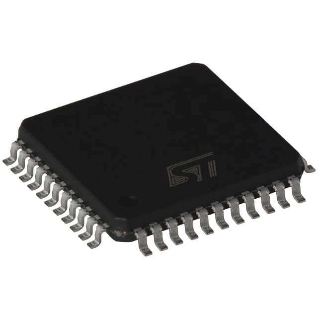
STMicroelectronics ST7538P013TR
- Part No.:
- ST7538P013TR
- Manufacturer:
- STMicroelectronics
- Category:
- Drivers, Receivers, Transceivers
- Package:
- 44-LQFP Exposed Pad
- Datasheet:
-
 ST7538P013TR.pdf
- Description:
- IC TRANSCEIVER HALF 1/1 44TQFPEP
- Quantity:
- Payment:

- Shipping:

Inventory:2,894
Please send an inquiry. Send us your inquiry, and we will respond immediately.
Product details
Overview
ST7538P013TR from STMicroelectronics is a half-duplex FSK power line transceiver IC integrating a programmable line driver, 5V linear regulator (100mA), carrier/preamble detection, zero-crossing synchronization, and watchdog timer. It operates from 7.5–12.5V single supply, consumes only 5mA quiescent current, supports 8 carrier frequencies (60–132.5kHz), and delivers up to 4800bps baud rate - deployed in EN 50065-compliant smart metering and home automation PLC networks.
For engineers reviewing the ST7538P013TR datasheet, ST7538P013TR pinout, ST7538P013TR application, or ST7538P013TR equivalent, key selection considerations include its integrated analog front-end for mains-coupled signaling, synchronous/asynchronous serial interface configuration, voltage/current-controlled PLI output compliance with CENELEC A-band limits, and register-based security checksum for firmware integrity.
Technical Context
The ST7538P013TR implements a fully integrated FSK modem architecture with dual-path analog signal chain: one path for high-sensitivity reception (250µVRMS) via RAI input and bandpass filtering, another for programmable transmission using DAC-driven ATO and DMOS-based ATOP1/ATOP2 outputs. Its internal PLL recovers clock during synchronous RX, while asynchronous mode relies on host timing recovery.
Control is managed through a 24-bit programmable register accessed via synchronous serial interface (CLR/T, RxD, TxD, REG_DATA, RxTx), enabling dynamic configuration of carrier frequency, baud rate, ALC gain steps (0.6–1.4dB), voltage/current control thresholds (VCLTH = 160–200mVPK, CCLTH = 1.80–2.00V), and zero-crossing detection hysteresis (±18mV).
Key Specifications
| Parameter | Value and Actual Design Meaning |
|---|---|
| Supply Voltage | 7.5–12.5V PAVcc; enables direct connection to unregulated AC-DC rails in metering applications |
| Quiescent Current | 5mA Iq; ensures low standby power for battery-backed or energy-harvested PLC nodes |
| Receiver Sensitivity | 250µVRMS (high-sensitivity mode); meets EN 50065 noise floor requirements for CENELEC A-band |
| Carrier Frequencies | 8 programmable options (60–132.5kHz); supports multi-channel hopping to avoid narrowband interference |
| Baud Rate | 600–4800bps; configurable via register bits; balances data throughput and robustness in noisy mains environments |
| Voltage Regulator | 5V ±2% output, 100mA max; powers external microcontrollers and logic without auxiliary LDO |
| Zero-Crossing Detection | ±45mV threshold with 1µs delay; enables precise phase-aligned transmission for reduced EMI and grid synchronization |
Pinout & Package
TQFP44 (slug-down) package with exposed thermal pad for enhanced power dissipation in continuous TX operation; pin 6 and pin 41 are substrate ground (GND) tied internally to AVss/DVss reference plane.
| Pin/Terminal | Circuit Role | Design Meaning |
|---|---|---|
| CD_PD (Pin 1) | Carrier/Preamble Detect Output | Digital flag indicating presence of valid FSK signal; used to trigger RX wake-up or channel arbitration logic |
| RxTx (Pin 4) | Mode Control Input | Active-high selects RX mode; active-low enables TX; internal pull-up eliminates need for external bias resistor |
| ATOP1 / ATOP2 (Pins 19, 21) | Power Line Driver Outputs | Dual-ended DMOS outputs delivering up to 7VPP AC into 1Ω load; support differential or single-ended coupling to mains |
| ZCIN / ZCOUT (Pins 16, 15) | Zero-Crossing Interface | ZCIN accepts AC mains waveform; ZCOUT provides synchronized digital edge for time-stamped TX initiation |
| VSENSE (Pin 29) | Voltage Control Feedback | Analog input monitoring output voltage; sets closed-loop regulation point for ATOP amplitude stability across line variations |
Key Features
| Feature | Design Value |
|---|---|
| Integrated Power Line Driver | Programmable voltage (3.5–7VPP) and current (250–370mArms) control via Vsense/CL pins - eliminates external amplifier stage |
| EN 50065 Compliance Engine | On-chip band-in-use detection (BU pin), carrier detection (CD_PD), and programmable filter tuning ensure automatic adherence to CENELEC spectral masks |
| Secure Register Access | 24-bit control register with checksum validation (REGOK pin); prevents corruption during SPI-like writes in electrically noisy environments |
| Dual-Mode Serial Interface | Configurable synchronous (master clock on CLR/T) or asynchronous (3-wire) host interface - simplifies integration with legacy MCUs lacking dedicated SPI |
| Self-Monitoring Functions | Watchdog timer (1.5s timeout), power-good flag (PG), and thermal-aware design (Rth-j-amb = 35°C/W) enable fail-safe operation in unattended deployments |
Applications
| Smart Electricity Metering | Home Automation PLC Hub |
|---|---|
|
Use Scenario: Two-way communication between utility meter and concentrator over 230V AC wiring, transmitting consumption data and tariff updates. IC Role / Device Role / Timing Role: FSK transceiver handling physical layer modulation/demodulation, zero-crossing synchronized burst transmission, and mains-coupled signal injection. Use Value: Meets EN 50065 Class A emission limits with integrated band-in-use detection, eliminating need for external spectrum sensing circuitry. |
Use Scenario: Central gateway relaying commands from smartphone app to lighting, HVAC, and appliance controllers via existing household wiring. IC Role / Device Role / Timing Role: Half-duplex modem managing shared medium access, preamble detection for collision avoidance, and adaptive baud rate switching (600–4800bps). Use Value: 250µVRMS receiver sensitivity enables reliable operation despite high attenuation (>60dB) in aged residential wiring. |
| Streetlight Remote Management | Industrial Building Energy Monitoring |
|
Use Scenario: Cluster controller collecting status and dimming feedback from LED streetlights over underground distribution lines. IC Role / Device Role / Timing Role: PLC node performing carrier detection before transmission, mains-zero-crossing alignment for low-EMI bursts, and watchdog reset supervision. Use Value: Integrated 5V/100mA regulator powers local MCU and sensors, reducing BOM count and board space in compact outdoor enclosures. |
Use Scenario: Submetering system aggregating HVAC, elevator, and chiller load profiles across multi-floor commercial buildings. IC Role / Device Role / Timing Role: Transceiver implementing programmable carrier frequency hopping (60–132.5kHz) to avoid interference from variable-frequency drives and UPS systems. Use Value: Programmable voltage/current control (via Vsense/CL) maintains consistent signal level across wide mains voltage fluctuations (±15%) typical in industrial feeders. |
Equivalent & Alternatives
The following parts are listed as comparable options for similar FSK power line transceiver applications.
| Alternative Part | Technical Difference | Application Difference | Selection Advice |
|---|---|---|---|
| TI TLK10031 | Differential line driver (±2.5V), no integrated voltage regulator, requires external 3.3V supply; supports higher baud rates (up to 115.2kbps) | Targeted at industrial Ethernet-over-power-line; lacks zero-crossing sync and EN 50065-specific features like BU/CD_PD | Choose when higher data rate and differential signaling are prioritized over regulatory compliance and system integration simplicity |
| Maxim MAX2990 | OFDM-based PLC PHY (not FSK), integrated MAC layer, 3.3V-only supply, no mains-coupled zero-crossing interface | Designed for G3-PLC and PRIME standards; incompatible with legacy FSK-based CENELEC A-band infrastructure | Choose only for greenfield deployments requiring IPv6 mesh networking and interoperability with G3-PLC ecosystem |
Compared with TLK10031 and MAX2990, the ST7538P013TR uniquely combines CENELEC A-band FSK modulation, zero-crossing synchronization, integrated 5V regulator, and hardware-level EN 50065 compliance functions - making it the sole option for cost-sensitive, standards-constrained smart meter upgrades.
Availability
ST7538P013TR is available at Aetrix Electronics and suitable for smart metering, home automation PLC hubs, streetlight remote management, and industrial building energy monitoring requiring stable component supply and long-term lifecycle support.
Supply support for ST7538P013TR includes scheduled delivery planning, volume procurement assistance, BOM continuity management, traceable sourcing, and lifecycle availability coordination for OEM customers, industrial embedded developers, connected-device designers, and electronics production programs.
Manufacturer
STMicroelectronics is a global semiconductor leader specializing in automotive, industrial, and power management ICs, with broad expertise in mixed-signal and high-voltage process technologies.
The ST7538 belongs to ST's legacy power line communication (PLC) transceiver product line, designed specifically for EN 50065-compliant narrowband FSK communication over AC mains in utility and building automation applications.
FAQ
What is the maximum allowed PAVcc slew rate during power-up?
The ST7538P013TR specifies a maximum power-up slope of 100 V/ms for PAVcc to prevent latch-up or internal regulator instability. Exceeding this rate may cause undefined behavior in the voltage control loop or premature activation of the power-good flag. This requirement is verified in Table 4 Absolute Maximum Ratings and applies regardless of DVcc/AVdd sequencing.
How does the band-in-use (BU) detection function operate?
The BU pin asserts high when signal energy within the currently programmed carrier band exceeds –85 dB/µVrms (typical), determined by internal RSSI measurement and digital threshold comparison. It is independent of carrier detection and remains active during both TX and RX modes, enabling real-time spectrum occupancy awareness for channel selection algorithms.
Can the ST7538P013TR drive a 50Ω load directly?
No - the ATOP1/ATOP2 outputs are optimized for high-impedance coupling to AC mains (typically >1kΩ via series capacitor). Driving 50Ω would exceed the specified 370mArms maximum current and risk thermal shutdown. For low-Z loads, an external step-up transformer or buffer amplifier is required per Figure 17 in the datasheet.
What happens if the REGOK pin goes high during normal operation?
A high REGOK signal indicates corruption of the 24-bit control register contents, typically caused by ESD event or voltage glitch on DVcc. The device continues operating with last-valid register values but disables new register writes until a full power cycle or watchdog reset clears the error state. No automatic recovery occurs in firmware.
ST7538P013TR Specifications
- Product attributes
- Attribute value
- Manufacturer:
- STMicroelectronics
- Series:
- -
- Package/Case:
- 44-LQFP Exposed Pad
- Packaging:
- Tape & Reel (TR)
- Product Status:
- Obsolete
- Type:
- Transceiver
- Protocol:
- -
- Number of Drivers/Receivers:
- 1/1
- Duplex:
- Half
- Receiver Hysteresis:
- -
- Data Rate:
- -
- Voltage - Supply:
- 4.75V ~ 5.25V
- Operating Temperature:
- -40°C ~ 85°C
- Grade:
- -
- Qualification:
- -
- Mounting Type:
- Surface Mount
- Supplier Device Package:
- 44-TQFP-EP (10x10)
ST7538P013TR FAQ
1.How can I place an order for ST7538P013TR through Aetrix?
Please submit a Request for Quotation (RFQ) for ST7538P013TR on Aetrix. Our sales agent will provide a competitive quotation and guide you through the order confirmation once you accept the terms.
2.Are the price and stock information for ST7538P013TR reliable?
The price and inventory of ST7538P013TR are updated periodically and may fluctuate due to market conditions. Stock and pricing data are typically refreshed every 24 hours. Quotation validity for ST7538P013TR is usually 5 days.
3.What payment methods are accepted for ST7538P013TR?
We accept Wire Transfer, PayPal, Credit Card, Western Union, MoneyGram, and Escrow for ST7538P013TR transactions.
Note: Certain payment methods may incur a processing fee.
4.How is shipping managed for ST7538P013TR?
ST7538P013TR orders can be shipped via leading logistics carriers, including DHL, UPS, FedEx, TNT, or Registered Mail.
Once your ST7538P013TR order is processed, you will receive an email with the shipment details and tracking number.
Note: Tracking information may take up to 24 hours to appear. Express delivery typically takes 3–5 business days.
5.How can I obtain technical support or documentation for ST7538P013TR?
For technical support, including ST7538P013TR datasheets, pinout diagrams, or application guidance, please contact our engineering support team. They can provide detailed documentation and assistance for your ST7538P013TR requirements.
6.How does Aetrix verify that ST7538P013TR is sourced from the original manufacturer or authorized distributors?
All ST7538P013TR products on Aetrix are procured from qualified distributors and authorized channels. Our dedicated quality assurance team conducts strict verification, including traceability checks and, if necessary, third-party testing. This ensures that ST7538P013TR meets industry standards.
7.What is the process for return or replacement of ST7538P013TR?
All ST7538P013TR units undergo pre-shipment inspection (PSI). If there is an issue with ST7538P013TR, returns or replacements are accepted under the following conditions:
1.Quantity discrepancies, incorrect items, or visible external defects (such as breakage or corrosion), acknowledged by Aetrix.
2.The issue is reported within 90 days of delivery.
3.The ST7538P013TR part is unused and in its original packaging.
Return procedure for ST7538P013TR:
1.Submit a request within 90 days.
2.Obtain a Return Material Authorization (RMA) from Aetrix.
ST7538P013TR Tags

-
ATA6561-GAQW-N
Microchip Technology

-
ATA6561-GBQW-N
Microchip Technology

-
AM26LS32ACDR
Texas Instruments

-
SP485CN-L/TR
MaxLinear, Inc.
-
SP485EN-L/TR
MaxLinear, Inc.
-
SP485EEN-L/TR
MaxLinear, Inc.
-
SP485ECN-L/TR
MaxLinear, Inc.
-
THVD1400DR
Texas Instruments
-
AM26C31IDR
Texas Instruments

-
TLIN1021ADRQ1
Texas Instruments
-
MAX232IDR
Texas Instruments
-
AM26C32IDR
Texas Instruments
Tech Hub

Operational amplifier guide covering op amp basics, feedback, ideal vs real op amps, common configurations, buffer circuits, offset, bias current, gain-bandwidth, slew rate, rail-to-rail limits and sel…

Jumper cables guide covering safe connection order, red and black clamp placement, final ground connection, cable gauge, length, clamp quality, copper vs CCA cables, jump starter comparison and battery…

LDO regulator guide covering low dropout voltage, power dissipation, thermal design, PSRR, output noise, capacitor stability, adjustable LDO circuits, LDO vs buck converter and datasheet selection chec…

Conditional Access Module guide covering CAM meaning, CI/CI+ interface, smart card authorization, DVB security workflow, TV and set-top box compatibility, internal electronics, ESD protection, connecto…

Guide to electronic component obsolescence covering EOL risk, PCN/PDN notices, last-time buy planning, replacement options, form-fit-function validation, counterfeit risk and BOM lifecycle management.

18650 battery guide covering lithium-ion cell basics, 3.6V/3.7V voltage, 4.2V charging, mAh and Wh capacity, protected cells, chargers, BMS, series-parallel packs, holders, welding and sourcing checks.…

Hall effect sensor guide covering working principle, linear and digital sensors, Arduino circuits, current sensing, speed detection, automotive applications, A3144 examples, signal filtering and datash…

Product Change Notification guide for electronic components, covering PCN meaning, PCN vs PDN/EOL, common change types, risk levels, form-fit-function review, engineering validation, BOM control, LTB/L…

A practical guide to blend door actuators, covering HVAC function, symptoms, location, AC and heater issues, reset and calibration, replacement cost, electrical diagnosis, compatibility checks, and rep…

Engineering guide to Raspberry Pi alternatives, covering chip-level differences, Orange Pi, ROCK, Jetson, Banana Pi, NanoPi, Compute Module, Pico, GPIO, camera, HAT compatibility, and replacement risks…


