
 My Inquiry
 My Account


STMicroelectronics ST7540
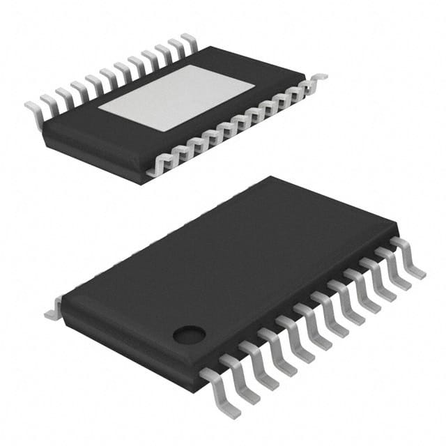
- Part No.:
- ST7540
- Manufacturer:
- STMicroelectronics
- Category:
- Drivers, Receivers, Transceivers
- Package:
- 28-TSSOP (0.173", 4.40mm Width) Exposed Pad
- Datasheet:
-
 ST7540.pdf
- Description:
- IC TRANSCEIVER HALF 1/1 28HTSSOP
- Quantity:
- Payment:

- Shipping:

Inventory:1,635
Please send an inquiry. Send us your inquiry, and we will respond immediately.
Product details
Overview
ST7540 from STMicroelectronics is a half-duplex FSK power line transceiver integrating a programmable power line driver, dual linear regulators (5V/3.3V, 50mA each), UART/SPI host interface, and carrier/preamble detection logic. It operates from a single 7.5–13.5V supply, consumes only 5mA quiescent current, and supports up to 4800 BPS baud rate with 250µVRMS receiving sensitivity for EN 50065-compliant smart metering and home automation networks.
For engineers reviewing the ST7540 datasheet, ST7540 pinout, ST7540 application, or ST7540 equivalent, key selection criteria include mains access mode (synchronous/asynchronous), programmable transmission frequency (60–132.5 kHz), voltage/current-controlled line driver configuration, and integrated watchdog timer behavior in power-line noise environments.
Technical Context
The ST7540 implements an FSK modem with eight selectable carrier frequencies (60–132.5 kHz) and four programmable baud rates (600–4800 BPS), where mark/space tones are derived via ∆F = Baud Rate × Deviation (0.5 or 1.0). Its internal PLL recovers bit timing in synchronous reception mode, while asynchronous mode delegates timing to the host controller.
Power line interfacing is managed through a DMOS-based power amplifier with programmable output voltage (via Vsense) and current limiting (via CL pin with 1.4kΩ resistor), enabling compliance with CENELEC Band A (3–95 kHz) emission limits. The device integrates two independent linear regulators - one delivering 5V @ 50mA (VDC), the other 3.3V @ 50mA (VDD) - both featuring short-circuit protection and thermal shutdown.
Key Specifications
| Parameter | Value and Actual Design Meaning |
|---|---|
| Supply Voltage | 7.5–13.5V single analog rail; enables direct connection to AC/DC adapter or battery-backed meter supply without external DC-DC. |
| Quiescent Current | 5mA at VCC=9V; ensures ultra-low standby power for battery-assisted or energy-harvested PLC nodes. |
| Receiving Sensitivity | 250µVRMS in high-sensitivity mode; supports reliable demodulation under high-attenuation (>60dB) power-line channel conditions. |
| Baud Rate | Up to 4800 BPS; balances data throughput and noise immunity for firmware updates and tariff switching in smart meters. |
| Carrier Frequencies | 8 programmable options (60, 66, 72, 76, 82.05, 86, 110, 132.5 kHz); allows dynamic channel hopping to avoid narrowband interference. |
| Line Driver Output | 500mArms max into 1Ω load (RCL=1.4kΩ); meets EN 50065 peak voltage requirements for CENELEC Band A. |
| Digital Interface | Configurable UART or SPI; eliminates need for protocol translation ICs in microcontroller-based meter designs. |
Pinout & Package
HTSSOP28 exposed pad package (5.0×6.2 mm, 0.65 mm pitch) with thermal pad for enhanced power dissipation in mains-connected applications.
| Pin/Terminal | Circuit Role | Design Meaning |
|---|---|---|
| PA_IN+, PA_IN− | Differential input to power line amplifier | Accepts feedback signal from external current-sense resistor for closed-loop current control. |
| PA_OUT | Power line driver output | Delivers FSK-modulated signal directly to coupling transformer; rated for 650mArms pulsed current. |
| VSENSE | Voltage control loop reference | Sets output voltage level (160–200mVPK threshold); enables precise amplitude regulation across temperature. |
| CL | Current limit feedback | Connects to SVSS via 1.4kΩ resistor to set 500mArms current limit; includes 80pF on-chip filtering. |
| RxTx | Mode select (RX/TX) | Active-low input: '0' enables transmit path, '1' enables receive path; controls internal signal routing. |
| CD_PD | Carrier/preamble detect output | Active-low open-drain flag indicating valid carrier or frame header presence; used for wake-up triggering. |
| BU/THERM | Band-in-use / thermal event flag | In RX: '1' indicates signal detected within selected band; in TX: '1' latches thermal shutdown event. |
| UART/SPI | Interface mode select | High = UART, Low = SPI; configures serial peripheral without firmware reconfiguration. |
Key Features
| Feature | Design Value |
|---|---|
| Programmable mains access | Synchronous (ST7540-generated clock) or asynchronous (host-controlled timing) operation - simplifies integration with legacy MCU UART peripherals. |
| Integrated dual regulators | 5V@50mA + 3.3V@50mA outputs eliminate need for external LDOs; short-circuit protected for field-reliability in unregulated power environments. |
| Header recognition | 8-bit or 16-bit configurable frame header detection reduces false wake-ups in multi-node PLC networks. |
| Watchdog timer | Configurable timeout (1.5s typical); resets system on host software hang during long-duration PLC bursts or noise-induced lockups. |
| Band-in-use detection | Real-time monitoring of spectral occupancy at selected carrier frequency; prevents collisions in shared-band PLC deployments. |
Applications
| Smart Electricity Metering | Home Area Network (HAN) |
|---|---|
Use Scenario: Two-way communication between utility meter and concentrator over low-voltage power lines in residential buildings. IC Role / Device Role / Timing Role: FSK transceiver handling physical layer modulation/demodulation, line driving, and carrier sensing per EN 50065-1. Use Value: 250µVRMS sensitivity and programmable 60–132.5 kHz carriers enable robust link establishment despite transformer isolation and household appliance noise. | Use Scenario: Interconnecting thermostats, lighting controllers, and plug-load monitors using existing AC wiring. IC Role / Device Role / Timing Role: Half-duplex PLC modem providing UART/SPI bridge between MCU and power line; manages synchronous bit timing recovery. Use Value: Integrated 5V/3.3V regulators power both host MCU and external coupling circuitry, reducing BOM count by two LDOs. |
| Streetlight Remote Management | Industrial Building Automation |
Use Scenario: Centralized control of LED streetlights via medium-voltage distribution lines using CENELEC-compliant signaling. IC Role / Device Role / Timing Role: Power line interface IC implementing FSK modulation, programmable current-limited driver, and band-in-use detection. Use Value: 500mArms programmable line drive meets EN 50065 emission limits while maintaining >3km range on MV lines with passive coupling. | Use Scenario: Retrofitting legacy HVAC and security panels with remote monitoring capability using building-wide AC infrastructure. IC Role / Device Role / Timing Role: PLC transceiver with watchdog timer and header recognition ensuring deterministic message delivery in noisy industrial environments. Use Value: Watchdog reset output (RSTO) and thermal shutdown flag (BU/THERM) provide fail-safe behavior during extended transmission bursts or ambient temperature excursions. |
Equivalent & Alternatives
The following parts are listed as comparable options for similar FSK power line transceiver applications.
| Alternative Part | Technical Difference | Application Difference | Selection Advice |
|---|---|---|---|
| ST7538 | Same pinout and register map; lacks integrated 3.3V regulator and band-in-use detection. | Requires external 3.3V LDO; unsuitable for systems needing real-time spectral occupancy monitoring. | Select when cost-sensitive designs can accept external regulation and simplified spectral management. |
| AMIS-49587 | Higher integration (integrated coupling transformer driver); supports OFDM in addition to FSK; requires 3.3V-only digital supply. | Targets higher-throughput AMI/AMI+ networks; not drop-in compatible due to different interface timing and register structure. | Select for next-gen smart grid deployments requiring >10 kbps throughput and multi-carrier resilience. |
Compared with ST7540, ST7538 reduces system cost but increases external component count and removes spectral awareness, while AMIS-49587 offers superior data rate and noise immunity at the expense of design complexity and non-interchangeable firmware.
Availability
ST7540 is available at Aetrix Electronics and suitable for smart metering, home area networking, streetlight control, and industrial building automation requiring stable component supply across extended product lifecycles.
Supply support for ST7540 includes scheduled delivery planning, volume procurement assistance, BOM continuity management, traceable sourcing, and lifecycle availability coordination for OEM customers, industrial embedded developers, connected-device designers, and electronics production programs.
Manufacturer
STMicroelectronics is a global semiconductor leader specializing in automotive, industrial, and power management solutions, with deep expertise in mixed-signal ASICs and power line communication technologies.
The ST7540 belongs to ST's dedicated PLC transceiver product line designed specifically for CENELEC-compliant, low-cost, low-power smart grid infrastructure - emphasizing integration, regulatory compliance, and field reliability over raw speed.
FAQ
What is the maximum allowable VCC slew rate during power-up?
The ST7540 specifies a maximum VCC slope of 100 V/ms during power-up to prevent latch-up or undefined register states. Exceeding this rate may cause improper initialization of the internal voltage regulators or control logic, leading to failed carrier detection or corrupted SPI/UART communication until full reset.
How does the CL pin set the line driver current limit?
The CL pin connects to SVSS via an external resistor (e.g., 1.4kΩ) to establish a reference voltage (1.80–2.00V) for the current control loop. This sets the maximum PA_OUT output current to 500mArms under specified load conditions, ensuring EN 50065 compliance without requiring external current-sense amplifiers or discrete MOSFETs.
Can the ST7540 operate with only the 5V regulator enabled?
Yes - the 5V regulator (VDC) and 3.3V regulator (VDD) operate independently. If the digital supply is provided externally at 3.3V, VDD can be left unconnected while VDC powers external circuitry. However, the internal logic still requires VDD or an external 3.3V source; disabling both regulators without external supply will halt operation.
What determines the carrier detection time (TCD) value?
TCD is programmable via Control Register bits 9 and 10, selecting values of 500µs, 1ms, 3ms, or 5ms. Shorter times improve responsiveness to burst transmissions but increase false detection risk in noisy environments; longer times enhance noise immunity at the cost of latency in wake-up or preamble acquisition.
ST7540 Specifications
- Product attributes
- Attribute value
- Manufacturer:
- STMicroelectronics
- Series:
- -
- Package/Case:
- 28-TSSOP (0.173", 4.40mm Width) Exposed Pad
- Packaging:
- Tube
- Product Status:
- Active
- Type:
- Transceiver
- Protocol:
- -
- Number of Drivers/Receivers:
- 1/1
- Duplex:
- Half
- Receiver Hysteresis:
- -
- Data Rate:
- -
- Voltage - Supply:
- 5V ~ 9V
- Operating Temperature:
- -40°C ~ 85°C
- Grade:
- -
- Qualification:
- -
- Mounting Type:
- Surface Mount
- Supplier Device Package:
- 28-HTSSOP
ST7540 FAQ
1.How can I place an order for ST7540 through Aetrix?
Please submit a Request for Quotation (RFQ) for ST7540 on Aetrix. Our sales agent will provide a competitive quotation and guide you through the order confirmation once you accept the terms.
2.Are the price and stock information for ST7540 reliable?
The price and inventory of ST7540 are updated periodically and may fluctuate due to market conditions. Stock and pricing data are typically refreshed every 24 hours. Quotation validity for ST7540 is usually 5 days.
3.What payment methods are accepted for ST7540?
We accept Wire Transfer, PayPal, Credit Card, Western Union, MoneyGram, and Escrow for ST7540 transactions.
Note: Certain payment methods may incur a processing fee.
4.How is shipping managed for ST7540?
ST7540 orders can be shipped via leading logistics carriers, including DHL, UPS, FedEx, TNT, or Registered Mail.
Once your ST7540 order is processed, you will receive an email with the shipment details and tracking number.
Note: Tracking information may take up to 24 hours to appear. Express delivery typically takes 3–5 business days.
5.How can I obtain technical support or documentation for ST7540?
For technical support, including ST7540 datasheets, pinout diagrams, or application guidance, please contact our engineering support team. They can provide detailed documentation and assistance for your ST7540 requirements.
6.How does Aetrix verify that ST7540 is sourced from the original manufacturer or authorized distributors?
All ST7540 products on Aetrix are procured from qualified distributors and authorized channels. Our dedicated quality assurance team conducts strict verification, including traceability checks and, if necessary, third-party testing. This ensures that ST7540 meets industry standards.
7.What is the process for return or replacement of ST7540?
All ST7540 units undergo pre-shipment inspection (PSI). If there is an issue with ST7540, returns or replacements are accepted under the following conditions:
1.Quantity discrepancies, incorrect items, or visible external defects (such as breakage or corrosion), acknowledged by Aetrix.
2.The issue is reported within 90 days of delivery.
3.The ST7540 part is unused and in its original packaging.
Return procedure for ST7540:
1.Submit a request within 90 days.
2.Obtain a Return Material Authorization (RMA) from Aetrix.
ST7540 Tags

-
ATA6561-GAQW-N
Microchip Technology

-
ATA6561-GBQW-N
Microchip Technology

-
AM26LS32ACDR
Texas Instruments

-
SP485CN-L/TR
MaxLinear, Inc.
-
SP485EN-L/TR
MaxLinear, Inc.
-
SP485EEN-L/TR
MaxLinear, Inc.
-
SP485ECN-L/TR
MaxLinear, Inc.
-
THVD1400DR
Texas Instruments
-
AM26C31IDR
Texas Instruments

-
TLIN1021ADRQ1
Texas Instruments
-
MAX232IDR
Texas Instruments
-
AM26C32IDR
Texas Instruments
Tech Hub

Operational amplifier guide covering op amp basics, feedback, ideal vs real op amps, common configurations, buffer circuits, offset, bias current, gain-bandwidth, slew rate, rail-to-rail limits and sel…

Jumper cables guide covering safe connection order, red and black clamp placement, final ground connection, cable gauge, length, clamp quality, copper vs CCA cables, jump starter comparison and battery…

LDO regulator guide covering low dropout voltage, power dissipation, thermal design, PSRR, output noise, capacitor stability, adjustable LDO circuits, LDO vs buck converter and datasheet selection chec…

Conditional Access Module guide covering CAM meaning, CI/CI+ interface, smart card authorization, DVB security workflow, TV and set-top box compatibility, internal electronics, ESD protection, connecto…

Guide to electronic component obsolescence covering EOL risk, PCN/PDN notices, last-time buy planning, replacement options, form-fit-function validation, counterfeit risk and BOM lifecycle management.

18650 battery guide covering lithium-ion cell basics, 3.6V/3.7V voltage, 4.2V charging, mAh and Wh capacity, protected cells, chargers, BMS, series-parallel packs, holders, welding and sourcing checks.…

Hall effect sensor guide covering working principle, linear and digital sensors, Arduino circuits, current sensing, speed detection, automotive applications, A3144 examples, signal filtering and datash…

Product Change Notification guide for electronic components, covering PCN meaning, PCN vs PDN/EOL, common change types, risk levels, form-fit-function review, engineering validation, BOM control, LTB/L…

A practical guide to blend door actuators, covering HVAC function, symptoms, location, AC and heater issues, reset and calibration, replacement cost, electrical diagnosis, compatibility checks, and rep…

Engineering guide to Raspberry Pi alternatives, covering chip-level differences, Orange Pi, ROCK, Jetson, Banana Pi, NanoPi, Compute Module, Pico, GPIO, camera, HAT compatibility, and replacement risks…


