
 My Inquiry
 My Account


STMicroelectronics ST7540TR
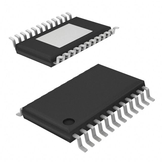
- Part No.:
- ST7540TR
- Manufacturer:
- STMicroelectronics
- Category:
- Drivers, Receivers, Transceivers
- Package:
- 28-TSSOP (0.173", 4.40mm Width) Exposed Pad
- Datasheet:
-
 ST7540TR.pdf
- Description:
- IC TRANSCEIVER HALF 1/1 28HTSSOP
- Quantity:
- Payment:

- Shipping:

Inventory:1,350
Please send an inquiry. Send us your inquiry, and we will respond immediately.
Product details
Overview
ST7540TR from STMicroelectronics is a half-duplex FSK power line transceiver integrating a programmable power line driver, dual linear regulators (5V/3.3V, 50mA each), UART/SPI host interface, and carrier/preamble detection logic. It operates from a single 7.5–13.5V supply, delivers up to 500mArms transmit current, supports 8 programmable carrier frequencies (60–132.5kHz), and achieves 250µVRMS receiving sensitivity per EN 50065 Cenelec compliance - deployed in smart metering and home automation PLC networks.
For engineers reviewing the ST7540TR datasheet, ST7540TR pinout, ST7540TR application, or ST7540TR equivalent, key selection criteria include mains access mode (synchronous/asynchronous), programmable voltage/current control of the PLI driver, integrated dual-regulator power architecture, and register-controlled FSK modulation parameters including baud rate (600–4800 BPS) and carrier frequency selection.
Technical Context
The ST7540TR implements a fully integrated FSK modem with internal PLL-based clock recovery for synchronous reception and configurable mark/space tone generation using eight selectable carrier frequencies (60–132.5kHz) and four baud rates (600–4800BPS) with deviation options (0.5× or 1× baud). Its power line interface includes a high-current DMOS output stage (PA_OUT) with programmable voltage/current control via Vsense and CL pins, enabling precise impedance matching to varying line conditions.
Control is executed through an 8/16-bit register map accessed via SPI or UART; features include carrier/preamble/frame header detection (CD_PD), band-in-use monitoring (BU/THERM), watchdog timer with reset output (RSTO), and thermal shutdown protection. The device uses Multipower BCD5 technology to co-integrate DMOS power stages, bipolar analog circuitry, and CMOS logic on a single die.
Key Specifications
| Parameter | Value and Actual Design Meaning |
|---|---|
| Supply Voltage | 7.5–13.5V single analog rail; powers both PLI driver and internal regulators |
| Quiescent Current | 5mA typical in standby; enables low-power metering node operation |
| Transmit Current | 500mArms max (programmable via CL resistor); supports 30Ω load per EN 50065 |
| Receive Sensitivity | 250µVRMS in high-sensitivity mode; meets Cenelec Class A noise immunity |
| Baud Rate Range | 600–4800BPS with selectable deviation; determines symbol timing and spectral occupancy |
| Carrier Frequencies | 8 programmable options (60, 66, 72, 76, 82.05, 86, 110, 132.5kHz); enables multi-channel hopping |
| Integrated Regulators | 5V/50mA and 3.3V/50mA linear regulators with short-circuit protection; eliminates external LDOs |
| Host Interface | Configurable UART or SPI; allows flexible MCU integration without protocol translation |
Pinout & Package
HTSSOP28 exposed pad package (6.4 × 9.7 mm, 0.65 mm pitch) with thermal pad for enhanced power dissipation in mains-connected applications.
| Pin/Terminal | Circuit Role | Design Meaning |
|---|---|---|
| PA_OUT | Power line driver output | High-current DMOS output (VCC−4.5Vpp swing); connects directly to coupling network |
| PA_IN+, PA_IN− | Differential amplifier inputs | High-impedance (1MΩ), low-offset (±18mV) inputs for feedback-controlled PLI voltage regulation |
| VSENSE | Voltage loop sensing input | Monitors output voltage via resistive divider; sets 160–200mVPK reference threshold |
| CL | Current limit feedback input | 80pF-filtered analog input; resistor-to-SVSS sets 1.8–2.0V threshold for 500mArms limit |
| CD_PD | Carrier/preamble detect output | Active-low open-drain signal indicating valid carrier, preamble, or frame header presence |
| BU/THERM | Band-in-use / thermal event flag | Indicates signal activity within selected band (Rx) or thermal shutdown (Tx) |
| RxTx | Mode control input | Active-low selects TX session; active-high enables RX demodulation path |
| REG_DATA | Register access selector | High = control register access; low = direct mains data path (bypasses register logic) |
| CLR/T | Clock or control strobe | Rising edge clocks data in synchronous mode; serves as register access strobe in control mode |
| RxD, TxD | Serial data I/O | CMOS-level UART interface; supports asynchronous host timing or synchronous bit sampling |
| VCC, VSS, SVSS, GND | Power and ground terminals | Separate analog (VSS/SVSS) and digital (GND) grounds prevent noise coupling into sensitive RX path |
| VDC, VDD | Regulated outputs | VDC = 5.05V ±5% @ 50mA; VDD = 3.3V ±5% @ 50mA; both include short-circuit foldback |
Key Features
| Feature | Design Value |
|---|---|
| Programmable mains access mode | Synchronous (ST7540-managed timing) or asynchronous (host-managed timing) - enables flexible system-level synchronization |
| Integrated dual-output regulators | Eliminates need for external 5V/3.3V LDOs; reduces BOM count and PCB area in space-constrained meters |
| Carrier/preamble/frame header detection | Hardware-accelerated detection reduces host CPU load and enables fast wake-up from low-power sleep states |
| Watchdog timer with RSTO output | Configurable timeout (1.5s typical); provides autonomous recovery from firmware lockup in unattended deployments |
| Thermal shutdown with BU/THERM flag | Protects against overtemperature during sustained high-current transmission; latched flag aids field diagnostics |
| 8-carrier frequency agility | Enables channel hopping to avoid narrowband interference in noisy power line environments |
Applications
| Smart Electricity Metering | Home Automation PLC Network |
|---|---|
|
Use Scenario: Two-way communication between utility meter and concentrator over 230V AC mains wiring. IC Role / Device Role / Timing Role: FSK transceiver handling physical layer modulation/demodulation, carrier detection, and mains-coupled driver amplification. Use Value: Meets EN 50065 spectral mask and sensitivity requirements while supporting 4800BPS throughput for firmware updates and tariff switching. |
Use Scenario: Inter-device command relay among lighting controllers, thermostats, and sensors using existing household wiring. IC Role / Device Role / Timing Role: Half-duplex PLC modem providing robust baseband FSK signaling with adaptive carrier selection to avoid appliance-generated noise. Use Value: Integrated 5V/3.3V regulators power host MCU and peripherals; low 5mA quiescent current extends battery backup life. |
| Streetlight Remote Monitoring | Industrial Building Energy Management |
|
Use Scenario: Centralized control of LED streetlights via medium-voltage distribution lines (MV/LV transformers). IC Role / Device Role / Timing Role: Power line interface IC managing synchronous burst transmission during zero-crossing windows to minimize grid disturbance. Use Value: Programmable mains access mode enables precise timing alignment with AC phase; thermal shutdown prevents driver latch-up under high ambient temperatures. |
Use Scenario: Retrofitting legacy HVAC and lighting systems with PLC-based control without new cabling. IC Role / Device Role / Timing Role: FSK transceiver with hardware preamble detection and 16-bit header recognition filtering out spurious noise bursts. Use Value: Dual-regulator outputs simplify power tree design; 250µVRMS sensitivity ensures reliable operation across long, lossy building wiring runs. |
Equivalent & Alternatives
The following parts are listed as comparable options for similar FSK power line transceiver applications.
| Alternative Part | Technical Difference | Application Difference | Selection Advice |
|---|---|---|---|
| ST7538 | Lacks integrated 5V regulator; requires external 5V supply; identical pinout and register map | Suitable where system already provides regulated 5V; lower BOM cost but higher design complexity | Select when 5V rail is available and thermal budget permits external regulation |
| MAX2990 | Higher integration: includes integrated coupler transformer driver; supports OFDM in addition to FSK | Targets newer G3-PLC and PRIME-compliant systems; requires different PHY layer firmware | Choose for next-gen deployments requiring multi-standard support and higher data rates |
Compared with ST7540TR, ST7538 reduces system cost by omitting the 5V regulator but increases external component count, while MAX2990 offers broader protocol support at the expense of higher complexity and non-drop-in replacement requirements.
Availability
ST7540TR is available at Aetrix Electronics and suitable for smart metering, home automation PLC networks, streetlight remote monitoring, and industrial building energy management requiring stable component supply across extended product lifecycles.
Supply support for ST7540TR includes scheduled delivery planning, volume procurement assistance, BOM continuity management, traceable sourcing, and lifecycle availability coordination for OEM customers, industrial embedded developers, connected-device designers, and electronics production programs.
Manufacturer
STMicroelectronics is a global semiconductor leader specializing in power management, analog, and microcontroller solutions for industrial, automotive, and consumer applications.
The ST7540TR belongs to ST's dedicated power line communication (PLC) transceiver product line, designed specifically for EN 50065-compliant narrowband FSK communication over AC mains infrastructure.
FAQ
What is the maximum allowable VCC slew rate during power-up?
The ST7540TR specifies a maximum VCC slew rate of 100 V/ms during power-up to ensure proper sequencing of internal regulators and analog blocks. Exceeding this rate may cause UVLO misbehavior or latch-up in the power line driver stage. This requirement is enforced by external RC networks on the VCC rail in certified meter designs.
How does the CL pin set the transmit current limit?
The CL pin accepts a resistor to SVSS that sets the current limit threshold (1.80–2.00V); with RCL = 1.4kΩ, the device limits PA_OUT current to 500mArms into a 30Ω load. The internal 80pF capacitor filters noise, making the loop immune to high-frequency mains transients.
Can the ST7540TR operate without an external crystal?
Yes - the X2 pin accepts an external CMOS clock signal (5Vpp, 2.5V DC level, 40–60% duty cycle) in lieu of a crystal. When using external clock, the X1 pin must be left unconnected; oscillator startup time and stability requirements no longer apply.
What is the function of the REG_DATA pin in synchronous vs. asynchronous mains access?
In synchronous mode, REG_DATA = high enables register access via CLR/T strobes; in asynchronous mode, REG_DATA = low routes TxD/RxD directly to the FSK modulator/demodulator, bypassing register-controlled timing logic. This pin determines whether the host controls timing or delegates it to the ST7540TR.
ST7540TR Specifications
- Product attributes
- Attribute value
- Manufacturer:
- STMicroelectronics
- Series:
- -
- Package/Case:
- 28-TSSOP (0.173", 4.40mm Width) Exposed Pad
- Packaging:
- Tape & Reel (TR)
- Product Status:
- Active
- Type:
- Transceiver
- Protocol:
- -
- Number of Drivers/Receivers:
- 1/1
- Duplex:
- Half
- Receiver Hysteresis:
- -
- Data Rate:
- -
- Voltage - Supply:
- 5V ~ 9V
- Operating Temperature:
- -40°C ~ 85°C
- Grade:
- -
- Qualification:
- -
- Mounting Type:
- Surface Mount
- Supplier Device Package:
- 28-HTSSOP
ST7540TR FAQ
1.How can I place an order for ST7540TR through Aetrix?
Please submit a Request for Quotation (RFQ) for ST7540TR on Aetrix. Our sales agent will provide a competitive quotation and guide you through the order confirmation once you accept the terms.
2.Are the price and stock information for ST7540TR reliable?
The price and inventory of ST7540TR are updated periodically and may fluctuate due to market conditions. Stock and pricing data are typically refreshed every 24 hours. Quotation validity for ST7540TR is usually 5 days.
3.What payment methods are accepted for ST7540TR?
We accept Wire Transfer, PayPal, Credit Card, Western Union, MoneyGram, and Escrow for ST7540TR transactions.
Note: Certain payment methods may incur a processing fee.
4.How is shipping managed for ST7540TR?
ST7540TR orders can be shipped via leading logistics carriers, including DHL, UPS, FedEx, TNT, or Registered Mail.
Once your ST7540TR order is processed, you will receive an email with the shipment details and tracking number.
Note: Tracking information may take up to 24 hours to appear. Express delivery typically takes 3–5 business days.
5.How can I obtain technical support or documentation for ST7540TR?
For technical support, including ST7540TR datasheets, pinout diagrams, or application guidance, please contact our engineering support team. They can provide detailed documentation and assistance for your ST7540TR requirements.
6.How does Aetrix verify that ST7540TR is sourced from the original manufacturer or authorized distributors?
All ST7540TR products on Aetrix are procured from qualified distributors and authorized channels. Our dedicated quality assurance team conducts strict verification, including traceability checks and, if necessary, third-party testing. This ensures that ST7540TR meets industry standards.
7.What is the process for return or replacement of ST7540TR?
All ST7540TR units undergo pre-shipment inspection (PSI). If there is an issue with ST7540TR, returns or replacements are accepted under the following conditions:
1.Quantity discrepancies, incorrect items, or visible external defects (such as breakage or corrosion), acknowledged by Aetrix.
2.The issue is reported within 90 days of delivery.
3.The ST7540TR part is unused and in its original packaging.
Return procedure for ST7540TR:
1.Submit a request within 90 days.
2.Obtain a Return Material Authorization (RMA) from Aetrix.
ST7540TR Tags

-
ATA6561-GAQW-N
Microchip Technology

-
ATA6561-GBQW-N
Microchip Technology

-
AM26LS32ACDR
Texas Instruments

-
SP485CN-L/TR
MaxLinear, Inc.
-
SP485EN-L/TR
MaxLinear, Inc.
-
SP485EEN-L/TR
MaxLinear, Inc.
-
SP485ECN-L/TR
MaxLinear, Inc.
-
THVD1400DR
Texas Instruments
-
AM26C31IDR
Texas Instruments

-
TLIN1021ADRQ1
Texas Instruments
-
MAX232IDR
Texas Instruments
-
AM26C32IDR
Texas Instruments
Tech Hub

A practical engineering and sourcing framework covering lifecycle verification, lifetime-buy calculations, replacement qualification, supplier checks and counterfeit-risk controls.

TTL and CMOS logic families differ in thresholds, loading, output drive, power and timing. This engineering guide compares 74HC and 74HCT, calculates noise margins and checks 3.3 V/5 V compatibility.

A practical engineering guide to 3.3V and 5V logic compatibility, input thresholds, resistor dividers, translator ICs, MOSFET level shifting, I2C pull-ups, timing limits and power-sequencing risks.

The 74HC595 uses push-pull logic outputs, while the TPIC6B595 uses 50 V open-drain DMOS sinks for higher-power loads. This guide compares timing, current limits, 3.3 V interfacing, load wiring, thermal…

The 74HC595 converts serial data into eight stable parallel outputs. This guide covers pin functions, shift and storage timing, OE and MR behavior, drive-current limits, cascading, voltage compatibilit…

A technical comparison of level-sensitive latches and edge-triggered flip-flops, covering timing windows, setup and hold limits, master–slave operation, time borrowing, race-through, HDL inference and…

A D latch stores one bit while Enable controls when data can pass. This reference covers gate-level operation, truth tables, transparency, setup and hold timing, LE versus OE, common ICs and practical …

An SR latch stores one bit through cross-coupled feedback. This engineering reference covers NOR and NAND implementations, truth tables, forbidden-state recovery, gated operation, switch debouncing, fa…

Latch circuits retain one bit through feedback. This technical reference covers SR and D latches, truth tables, transparency, timing limits, latch-versus-flip-flop behavior, applications and common log…

An engineering guide to LED driver operation, constant-current and constant-voltage outputs, linear and switching topologies, dimming, IC selection, calculations, replacement compatibility, and fault c…


