
 My Inquiry
 My Account


STMicroelectronics ST8500
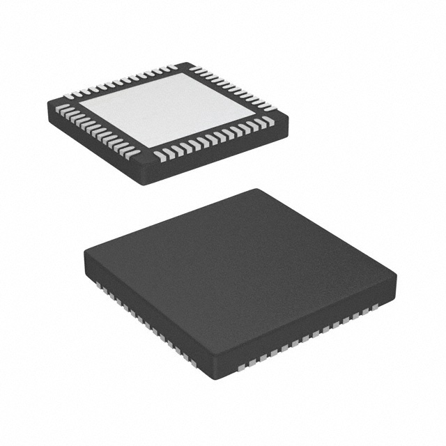
- Part No.:
- ST8500
- Manufacturer:
- STMicroelectronics
- Category:
- Telecom
- Package:
- 56-VFQFN Exposed Pad
- Datasheet:
-
 ST8500.pdf
- Description:
- IC TELECOM INTERFACE 56QFN
- Quantity:
- Payment:

- Shipping:

Inventory:1,552
Please send an inquiry. Send us your inquiry, and we will respond immediately.
Product details
Overview
ST8500 from STMicroelectronics is a programmable power line communication (PLC) System-on-Chip integrating a differential analog front-end (PGA, ADC, DAC, zero-crossing comparator), real-time engine (400 MHz max) for PHY/MAC processing, and ARM Cortex-M4F core (200 MHz) with 256 kB SRAM, AES crypto engine, and QFN56 package. It supports CENELEC/FCC/ARIB-compliant smart metering and grid communications up to 500 kHz bandwidth.
For engineers reviewing the ST8500 datasheet, ST8500 pinout, ST8500 application, or ST8500 equivalent, this page delivers verified technical context on PLC signal chain architecture, dual-core timing partitioning, cryptographic acceleration, low-power mode sequencing, and QFN56 thermal/power layout constraints - all critical for interoperable G3-PLC® and PRIME protocol implementation.
Technical Context
The ST8500 implements a split-processor architecture: the dedicated real-time engine (RTE) handles time-critical PLC physical layer tasks-including modulation/demodulation, FEC (Viterbi, Reed-Solomon), and sample-rate-synchronized ADC/DAC control-while the ARM Cortex-M4F core manages upper-layer protocol stacks, peripheral I/O, and secure key management via OTP and AES-128/192/256.
Its analog front-end supports differential PLC coupling with automatic gain control, 500 kHz signal bandwidth, zero-crossing timestamp capture via GPT0, and integrated thermal/current sensing for line driver protection. Clocking relies on a 25 MHz external crystal feeding an internal frequency synthesizer to generate independent clocks for RTE, Cortex-M4F, and peripherals.
Key Specifications
| Parameter | Value and Actual Design Meaning |
|---|---|
| PLC Bandwidth | DC to 500 kHz - enables full CENELEC A/B/C/D, FCC Part 15, and ARIB STD-T108 compliance without external filtering. |
| Real-Time Engine Max Frequency | 400 MHz - provides deterministic execution for G3-PLC® OFDM symbol processing and forward error correction in sub-100 µs latency windows. |
| Cortex-M4F Core Frequency | 200 MHz - delivers sufficient throughput for PRIME stack management, TLS handshake offload, and multi-interface coordination (3× SPI, 2× USART, I²C). |
| Embedded Memory | 256 kB SRAM (code/data), 96 kB SRAM (data only), 8 kB shared RAM, 16 kB ROM bootloader, OTP - supports dual-firmware storage and secure key isolation. |
| Crypto Acceleration | AES-128/192/256 + TRNG + PRNG - enables hardware-accelerated encryption for DLMS/COSEM message confidentiality and device authentication. |
| Power Supply | 3.3 V (I/O/analog), 2.5 V (internal analog regulator), 1.1 V (digital) - separates noise-sensitive analog paths from digital switching domains. |
| Operating Temperature | –40 °C to +105 °C - qualified for outdoor smart meter and distribution transformer monitoring environments. |
Pinout & Package
ST8500 is housed in a 7 mm × 7 mm × 1 mm QFN56 package with exposed thermal pad, optimized for high-density PLC modem PCB layouts requiring low-inductance analog grounding and thermal dissipation under continuous line-driver operation.
| Pin/Terminal | Circuit Role | Design Meaning |
|---|---|---|
| VDDA_2P5 | Analog supply (2.5 V) | Powers PGA, ADC, DAC, and zero-crossing comparator - requires local 1 µF ceramic decoupling adjacent to pin. |
| VDDIO_3P3 | I/O supply (3.3 V) | Drives GPIOs, USART, SPI, I²C interfaces - shared with external transceiver logic levels. |
| VDDD_1P1 | Digital core supply (1.1 V) | Feeds Cortex-M4F and RTE logic - must be regulated independently to avoid voltage droop during burst processing. |
| XTAL_IN / XTAL_OUT | 25 MHz crystal interface | Connects to fundamental-mode 25 MHz crystal; internal oscillator eliminates need for external clock source. |
| RX_P / RX_N | Differential PLC receive inputs | High-impedance inputs to PGA - require matched 50 Ω PCB routing and common-mode choke for EMI suppression. |
| TX_P / TX_N | Differential PLC transmit outputs | Drive external line driver (e.g., STLD1) - output swing referenced to VDDA_2P5; current-limited by internal pre-driver. |
| ZC_IN | Zero-crossing comparator input | Accepts bipolar AC mains signal (±1 V); triggers GPT0 timestamp capture for synchronized PLC frame alignment. |
| SWDIO / SWCLK | ARM Serial Wire Debug | Enables non-intrusive firmware update and real-time trace during field deployment without JTAG header. |
Key Features
| Feature | Design Value |
|---|---|
| Dual-core partitioning | Hardware-isolated RTE and Cortex-M4F cores prevent PHY-layer jitter from disrupting upper-layer protocol timing or security operations. |
| Programmable AFE gain control | Automatic PGA gain adjustment maintains ADC dynamic range across varying line impedance (1–100 Ω) and noise floor (up to 120 dBµV). |
| Integrated zero-crossing timestamping | GPT0 captures ZC event with ≤100 ns resolution - enables precise OFDM symbol boundary alignment required by G3-PLC® time-slicing. |
| Multi-domain power management | Four low-power modes (Normal, Slow, Doze, Low Power) allow independent clock gating of RTE, Cortex-M4F, and peripherals - reduces active current to 35 mA typical at 200 MHz. |
| Secure boot & key storage | OTP memory includes dedicated secure key zones and user-configurable fields - prevents cloning and supports field firmware authentication via ECDSA signatures. |
Applications
| Smart Electricity Meter | G3-PLC® Grid Node |
|---|---|
Use Scenario: Two-way communication between utility head-end and residential meter over LV power lines. IC Role / Device Role / Timing Role: Full PLC modem SoC handling PHY/MAC layers, secure DLMS/COSEM messaging, and zero-crossing-synchronized frame transmission. Use Value: Enables certified CENELEC EN50065 Class A compliance with <15 ms end-to-end latency and 99.9% packet success rate at –90 dBm SNR. |
Use Scenario: Distribution transformer monitor relaying phase voltage, current, and harmonic data upstream. IC Role / Device Role / Timing Role: Real-time engine processes OFDM symbols while Cortex-M4F aggregates sensor data and executes IEEE 1377 (SEP2) profile. Use Value: Achieves 500 kbps effective throughput using G3-PLC® adaptive tone mapping and FEC - sustaining >10 km line reach with repeater support. |
| PRIME-based Water Meter Network | ARIB STD-T108 Streetlight Controller |
Use Scenario: Battery-powered water meters transmitting hourly consumption data via PRIME v1.4 mesh network. IC Role / Device Role / Timing Role: Manages PRIME MAC layer, AES-128 encrypted payload generation, and ultra-low-power wake-up on scheduled TX slot. Use Value: Leverages Doze mode (2.1 µA standby) and RTC-triggered wake-up to extend battery life beyond 15 years with 2000+ transmissions/year. |
Use Scenario: Outdoor LED streetlight with remote dimming, fault reporting, and energy logging via Japanese power line standard. IC Role / Device Role / Timing Role: Implements ARIB STD-T108 physical layer with 10–450 kHz band selection and built-in notch filtering for fluorescent lamp noise rejection. Use Value: Delivers 98% link reliability in high-noise urban environments through adaptive AGC and real-time interference detection in DFE. |
Equivalent & Alternatives
The following parts are listed as comparable options for similar PLC modem SoC applications.
| Alternative Part | Technical Difference | Application Difference | Selection Advice |
|---|---|---|---|
| MAX2992 | Single-core ARM Cortex-M3 (120 MHz); no dedicated RTE; 12-bit ADC only; supports up to 200 kHz bandwidth. | Limited to legacy PRIME v1.3 and narrowband PLC; lacks G3-PLC® OFDM acceleration and zero-crossing timestamping. | Choose for cost-sensitive, low-data-rate AMI deployments where CENELEC B-band suffices and AES-256 is not required. |
| QCA7000 | Wi-Fi coexistence-focused SoC; uses proprietary PHY; no ARM core - runs fixed firmware; no OTP or TRNG. | Designed for home-area networks (HAN), not utility-grade grid communication; fails CENELEC immunity testing. | Use only in consumer-grade smart plugs or HVAC controllers where regulatory certification is not mandated. |
Compared with MAX2992 and QCA7000, the ST8500 uniquely combines dual-core determinism, 500 kHz bandwidth, hardware crypto, and zero-crossing synchronization - making it the only SoC qualified for G3-PLC® Tier-2 certification and DLMS/COSEM Level-3 security in utility-grade deployments.
Availability
ST8500 is available at Aetrix Electronics and suitable for smart metering, grid automation, and IoT infrastructure projects requiring stable component supply, long-term lifecycle assurance, and full regulatory documentation (CENELEC, FCC, ARIB).
Supply support for ST8500 includes scheduled delivery planning, volume procurement assistance, BOM continuity management, traceable sourcing, and lifecycle availability coordination for OEM customers, industrial embedded developers, connected-device designers, and electronics production programs.
Manufacturer
STMicroelectronics is a global semiconductor leader headquartered in Geneva, Switzerland, designing and manufacturing microcontrollers, analog ICs, power management, and automotive-grade silicon.
The ST8500 belongs to ST's Power Line Communication SoC product line, engineered specifically for interoperable, standards-compliant, and cryptographically secured smart grid communications - targeting utility-grade reliability and multi-decade field deployment.
FAQ
What regulatory standards does the ST8500 natively support?
The ST8500 is architected to meet CENELEC EN50065 (Europe), FCC Part 15 Subpart H (USA), and ARIB STD-T108 (Japan) requirements out-of-the-box. Its 500 kHz bandwidth, programmable notch filters, and AGC enable direct compliance without external components - validated in ST's reference designs ST8500-PLC-EVAL and ST8500-G3-PLC.
How is the real-time engine (RTE) isolated from the Cortex-M4F core?
The RTE and Cortex-M4F operate on separate clock domains with dedicated SRAM banks (RTE: 64 kB code/data; Cortex-M4F: 256 kB). Inter-processor communication occurs exclusively via the IPC mailbox and shared RAM with hardware semaphore protection - preventing timing interference during concurrent OFDM symbol processing and TLS stack execution.
Can the ST8500 drive a line coupler directly, or is an external driver required?
The ST8500's TX_P/TX_N outputs require an external line driver (e.g., STLD1 or TI THS6212) due to limited output current (±20 mA typical). Its internal pre-driver provides voltage gain only - not current amplification - and thermal/current sense signals are routed to the AFE for driver protection monitoring.
What debug interfaces are supported, and is JTAG mandatory for firmware development?
The ST8500 supports both Serial Wire Debug (SWD) and JTAG via SWJ-DP. SWD (SWDIO/SWCLK) is sufficient for full development - including flash programming, real-time trace, and breakpoint debugging - and uses only two pins. JTAG is optional and primarily used for boundary scan testing in production.
ST8500 Specifications
- Product attributes
- Attribute value
- Manufacturer:
- STMicroelectronics
- Series:
- -
- Package/Case:
- 56-VFQFN Exposed Pad
- Packaging:
- Tray
- Product Status:
- Discontinued at Digi-Key
- Function:
- Power Line Communication Modem (PLC)
- Interface:
- I2C, SPI, UART/USART
- Number of Circuits:
- 1
- Voltage - Supply:
- 2.3V ~ 2.75V, 3V ~ 3.6V
- Current - Supply:
- -
- Power (Watts):
- -
- Operating Temperature:
- -40°C ~ 105°C
- Grade:
- -
- Qualification:
- -
- Mounting Type:
- Surface Mount
- Supplier Device Package:
- 56-QFN (7x7)
ST8500 FAQ
1.How can I place an order for ST8500 through Aetrix?
Please submit a Request for Quotation (RFQ) for ST8500 on Aetrix. Our sales agent will provide a competitive quotation and guide you through the order confirmation once you accept the terms.
2.Are the price and stock information for ST8500 reliable?
The price and inventory of ST8500 are updated periodically and may fluctuate due to market conditions. Stock and pricing data are typically refreshed every 24 hours. Quotation validity for ST8500 is usually 5 days.
3.What payment methods are accepted for ST8500?
We accept Wire Transfer, PayPal, Credit Card, Western Union, MoneyGram, and Escrow for ST8500 transactions.
Note: Certain payment methods may incur a processing fee.
4.How is shipping managed for ST8500?
ST8500 orders can be shipped via leading logistics carriers, including DHL, UPS, FedEx, TNT, or Registered Mail.
Once your ST8500 order is processed, you will receive an email with the shipment details and tracking number.
Note: Tracking information may take up to 24 hours to appear. Express delivery typically takes 3–5 business days.
5.How can I obtain technical support or documentation for ST8500?
For technical support, including ST8500 datasheets, pinout diagrams, or application guidance, please contact our engineering support team. They can provide detailed documentation and assistance for your ST8500 requirements.
6.How does Aetrix verify that ST8500 is sourced from the original manufacturer or authorized distributors?
All ST8500 products on Aetrix are procured from qualified distributors and authorized channels. Our dedicated quality assurance team conducts strict verification, including traceability checks and, if necessary, third-party testing. This ensures that ST8500 meets industry standards.
7.What is the process for return or replacement of ST8500?
All ST8500 units undergo pre-shipment inspection (PSI). If there is an issue with ST8500, returns or replacements are accepted under the following conditions:
1.Quantity discrepancies, incorrect items, or visible external defects (such as breakage or corrosion), acknowledged by Aetrix.
2.The issue is reported within 90 days of delivery.
3.The ST8500 part is unused and in its original packaging.
Return procedure for ST8500:
1.Submit a request within 90 days.
2.Obtain a Return Material Authorization (RMA) from Aetrix.
ST8500 Tags

-
LMC567CMX/NOPB
Texas Instruments
-
LM567CMX/NOPB
Texas Instruments
-
LM567CM/NOPB
Texas Instruments

-
VSC8531XMW-02
Microchip Technology
-
VSC8531XMW-05
Microchip Technology

-
GPY115C0VI
MaxLinear, Inc.

-
SI32185-A-FMR
Skyworks Solutions Inc.

-
VSC8541XMV-05
Microchip Technology

-
SI32178-B-FM1R
Skyworks Solutions Inc.
-
GPY215C0VI
MaxLinear, Inc.

-
CPC7514ZTR
Littelfuse Inc.

-
VSC8502XML-03
Microchip Technology
Tech Hub

Counterfeit components can hide behind convincing markings and passing basic function tests. This engineering reference covers source traceability, external inspection, X-ray, XRF, electrical testing, …

A practical engineering and sourcing framework covering lifecycle verification, lifetime-buy calculations, replacement qualification, supplier checks and counterfeit-risk controls.

TTL and CMOS logic families differ in thresholds, loading, output drive, power and timing. This engineering guide compares 74HC and 74HCT, calculates noise margins and checks 3.3 V/5 V compatibility.

A practical engineering guide to 3.3V and 5V logic compatibility, input thresholds, resistor dividers, translator ICs, MOSFET level shifting, I2C pull-ups, timing limits and power-sequencing risks.

The 74HC595 uses push-pull logic outputs, while the TPIC6B595 uses 50 V open-drain DMOS sinks for higher-power loads. This guide compares timing, current limits, 3.3 V interfacing, load wiring, thermal…

The 74HC595 converts serial data into eight stable parallel outputs. This guide covers pin functions, shift and storage timing, OE and MR behavior, drive-current limits, cascading, voltage compatibilit…

A technical comparison of level-sensitive latches and edge-triggered flip-flops, covering timing windows, setup and hold limits, master–slave operation, time borrowing, race-through, HDL inference and…

A D latch stores one bit while Enable controls when data can pass. This reference covers gate-level operation, truth tables, transparency, setup and hold timing, LE versus OE, common ICs and practical …

An SR latch stores one bit through cross-coupled feedback. This engineering reference covers NOR and NAND implementations, truth tables, forbidden-state recovery, gated operation, switch debouncing, fa…

Latch circuits retain one bit through feedback. This technical reference covers SR and D latches, truth tables, transparency, timing limits, latch-versus-flip-flop behavior, applications and common log…


