
 My Inquiry
 My Account


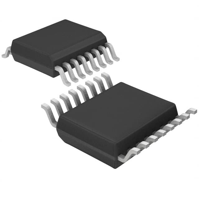
STMicroelectronics STAP08DP5XTTR
- Part No.:
- STAP08DP5XTTR
- Manufacturer:
- STMicroelectronics
- Category:
- LED Drivers
- Package:
- 16-TSSOP (0.173", 4.40mm Width) Exposed Pad
- Datasheet:
-
 STAP08DP5XTTR.pdf
- Description:
- IC LED DRVR LINEAR 100MA 16TSSOP
- Quantity:
- Payment:

- Shipping:

Inventory:1,851
Please send an inquiry. Send us your inquiry, and we will respond immediately.
Product details
Overview
STAP08DP5XTTR from STMicroelectronics is an AEC-Q100 qualified 8-bit constant-current LED sink driver for automotive lighting systems. It delivers regulated 5–100 mA per channel via external REXT, supports short/open output error detection without extra pins, and operates from 3.0–5.5 V supply - enabling direct interface with 3.3 V microcontrollers in dashboard backlighting applications.
For engineers reviewing the STAP08DP5XTTR datasheet, STAP08DP5XTTR pinout, STAP08DP5XTTR application, or STAP08DP5XTTR equivalent, this device is selected for high-reliability LED current control with integrated diagnostics, thermal-efficient TSSOP-16 exposed-pad packaging, and 30 MHz serial data throughput in space-constrained automotive modules.
Technical Context
The STAP08DP5XTTR integrates an 8-bit serial-in/parallel-out shift register feeding an 8-bit D-type storage register, driving eight independent constant-current sinks. Its detection circuitry monitors each output for open-circuit, short-to-GND, and short-to-VO conditions using dedicated logic on OE/DM2 and LE/DM1 pins - entering and exiting detection mode via defined 5-clock sequences without interrupting normal operation.
Current regulation is set by a single external resistor (REXT), enabling precise 5–100 mA per channel with ±1.5% channel-to-channel accuracy at VO ≥ 1.3 V. The device supports 20 V output voltage swing, allowing up to 6–7 LEDs in series per channel at typical forward voltages, and features 37.5 °C/W junction-to-ambient thermal resistance when the exposed pad is soldered to PCB ground.
Key Specifications
| Parameter | Value and Actual Design Meaning |
|---|---|
| Output channels | 8 independent constant-current sinks, each programmable 5–100 mA via REXT |
| Supply voltage | 3.0–5.5 V - enables direct use with 3.3 V MCUs and compatibility with automotive 5 V rails |
| Output voltage range | Up to 20 V - supports driving multiple LEDs in series (e.g., 6× 3.2 V white LEDs) |
| Max clock frequency | 30 MHz - ensures fast serial data loading for dynamic brightness updates in infotainment displays |
| Current accuracy | ±1.5% channel-to-channel at VO ≥ 1.3 V - maintains uniform LED brightness across all 8 channels |
| Thermal resistance | 37.5 °C/W (RthJA) - requires exposed pad soldering to PCB for rated thermal performance |
| Error detection | Detects open, short-to-GND, and short-to-VO per channel - reports status via SDO without added pins |
Pinout & Package
Package: HTSSOP16 exposed pad (TSSOP-16 with thermal pad), RoHS-compliant, ECOPACK®2 grade.
| Pin/Terminal | Circuit Role | Design Meaning |
|---|---|---|
| 1 GND | Ground reference | Primary return path for all output currents and internal logic; must be low-impedance connection |
| 2 SDI | Serial data input | Accepts 3.3 V–compatible logic-level data for shift register loading |
| 3 CLK | Serial clock input | 30 MHz max edge-triggered clock synchronizing data into shift register |
| 4 LE/DM1 | Latch input / Detection Mode 1 | Latches shift register to output register; also initiates detection mode entry/exit sequence |
| 5–12 OUT0–OUT7 | Constant-current sink outputs | Each drives LED cathodes with user-programmed current; supports 20 V compliance |
| 13 OE/DM2 | Output enable / Detection Mode 2 | Active-low output control; second pin in 5-cycle logic sequence for detection mode control |
| 14 SDO | Serial data output | Shifts out 8-bit error status or normal data; compatible with 3.3 V MCU inputs |
| 15 R-EXT | Current programming node | Connects external resistor to set all 8 output currents simultaneously (e.g., 3930 Ω → 10 mA) |
| 16 VDD | Power supply | 3.0–5.5 V input; powers logic and output stages; decoupling capacitor required near pin |
Key Features
| Feature | Design Value |
|---|---|
| AEC-Q100 Grade 1 qualification | Validated for automotive ambient temperatures (−40 °C to +125 °C junction), ensuring reliability in dashboard and exterior lighting |
| Integrated open/short detection | Per-channel fault reporting via SDO within 1 µs - eliminates need for external sense resistors or ADC monitoring |
| 3.3 V logic compatibility | Full operation with 3.3 V microcontrollers on SDI, CLK, LE/DM1, OE/DM2, and SDO - no level-shifting required |
| High thermal efficiency package | TSSOP-16 with exposed pad reduces RthJA to 37.5 °C/W - enables 100 mA/channel operation at +85 °C ambient with proper PCB layout |
| Adjustable PWM dimming | 0–100% brightness control via OE/DM2 pin - supports analog dimming without external PWM generator |
Applications
| Dashboard Backlighting | Infotainment Display Lighting |
|---|---|
|
Use Scenario: Driving segmented LCD backlight zones in instrument clusters with variable brightness per zone. IC Role / Device Role / Timing Role: Constant-current sink for 8 independent LED strings; provides uniform luminance and real-time open-circuit detection to prevent partial display failure. Use Value: Enables fail-safe backlight operation - detects and reports individual LED string opens before driver IC shutdown, supporting ASIL-B diagnostic coverage. |
Use Scenario: Powering RGB LED arrays behind touch-sensitive center-stack displays for dynamic UI feedback. IC Role / Device Role / Timing Role: Serially controlled 8-channel current sink; accepts rapid SPI-like updates at 30 MHz to synchronize color/brightness changes with GUI rendering. Use Value: Eliminates discrete current-setting resistors per channel - reduces BOM count and PCB area while maintaining ±1.5% current matching across colors. |
| Daytime Running Lights (DRL) | Interior Ambient Lighting |
|
Use Scenario: Driving linear LED strings in front-end DRL modules requiring precise current regulation and thermal robustness. IC Role / Device Role / Timing Role: High-voltage (20 V) sink driver supporting 5–7 LEDs in series per channel; uses REXT to set 80 mA nominal current per string. Use Value: Delivers stable light output over −40 °C to +105 °C ambient - avoids current drift-induced intensity variation during cold starts or under-hood heat soak. |
Use Scenario: Controlling multi-zone footwell and door-handle LED lighting with independent dimming and fault reporting. IC Role / Device Role / Timing Role: Low-voltage (3 V min) LED driver enabling direct integration with body-control module's 3.3 V domain; supports diagnostic readback via SDO. Use Value: Reduces system-level diagnostics complexity - replaces 8 discrete current regulators and 8 sense lines with one serial interface and built-in error flags. |
Equivalent & Alternatives
The following parts are listed as comparable options for similar LED sink driver applications.
| Alternative Part | Technical Difference | Application Difference | Selection Advice |
|---|---|---|---|
| TLC59116IPWPR | I²C interface, 16-channel, no built-in open/short detection, max 120 mA/channel, 5.5 V supply only | Requires I²C master and external fault monitoring; better suited for non-automotive consumer lighting | Select if I²C bus integration and higher channel count outweigh need for embedded diagnostics |
| MAX7219CWG+ | Common-cathode LED matrix driver, 8×8 segments, no current sink per pin, no open/short detection, 5.5 V only | Designed for 7-segment/LED matrix displays, not linear LED strings; lacks per-output current programming | Choose only for alphanumeric display panels - not a functional replacement for constant-current sink applications |
Compared with TLC59116IPWPR and MAX7219CWG+, the STAP08DP5XTTR uniquely combines AEC-Q100 qualification, per-channel open/short detection, 3.0 V operation, and serial-in/parallel-out architecture - making it the only drop-in solution for automotive LED backlighting requiring ISO 26262-aligned diagnostics and thermal resilience.
Availability
STAP08DP5XTTR is available at Aetrix Electronics and suitable for dashboard backlighting, exterior DRL modules, and infotainment display lighting requiring stable component supply, automotive-grade traceability, and long-term lifecycle support.
Supply support for STAP08DP5XTTR includes scheduled delivery planning, volume procurement assistance, BOM continuity management, traceable sourcing, and lifecycle availability coordination for OEM customers, industrial embedded developers, connected-device designers, and electronics production programs.
Manufacturer
STMicroelectronics is a global semiconductor leader headquartered in Geneva, Switzerland, specializing in automotive, industrial, and power management ICs with broad manufacturing and quality certifications.
The STAP08DP5XTTR belongs to ST's automotive LED driver product line, engineered specifically for AEC-Q100-compliant interior/exterior lighting systems where diagnostic integrity, thermal efficiency, and 3.3 V MCU interoperability are mandatory.
FAQ
What is the minimum supply voltage required for full functionality?
The STAP08DP5XTTR operates fully from 3.0 V to 5.5 V. At 3.0 V, all specifications including 30 MHz clock operation, 5–100 mA output current range, and error detection remain valid per datasheet Table 6. This enables direct use with 3.3 V automotive microcontrollers without level shifting or boost circuitry.
How does the open/short detection mode interact with normal LED driving?
Detection mode is entered and exited via a 5-clock-cycle logic sequence on OE/DM2 and LE/DM1 pins - it suspends normal LED driving temporarily. During detection, all outputs are forced ON, and fault status (open, short-to-GND, short-to-VO) is captured and shifted out via SDO within 1 µs. Normal operation resumes immediately after the sequence completes.
Can the STAP08DP5XTTR drive LEDs in series, and what is the maximum string voltage?
Yes - each OUTx pin supports up to 20 V output voltage swing relative to GND. With typical white LED forward voltages of ~3.2 V, this allows up to six 3.2 V LEDs (19.2 V total) in series per channel. The 20 V rating ensures margin for temperature-induced VF drift and transient spikes in automotive environments.
Is the exposed thermal pad electrically isolated or grounded?
The exposed pad is electrically isolated from internal circuitry per datasheet Note in Section 1.1. It must be soldered to a PCB thermal pad connected to system ground to achieve the specified 37.5 °C/W RthJA. No internal electrical connection exists - grounding is purely for thermal conduction and mechanical stability.
STAP08DP5XTTR Specifications
- Product attributes
- Attribute value
- Manufacturer:
- STMicroelectronics
- Series:
- -
- Package/Case:
- 16-TSSOP (0.173", 4.40mm Width) Exposed Pad
- Packaging:
- Tape & Reel (TR)
- Product Status:
- Active
- Type:
- Linear
- Topology:
- Shift Register
- Internal Switch(s):
- Yes
- Number of Outputs:
- 8
- Voltage - Supply (Min):
- 3V
- Voltage - Supply (Max):
- 5.5V
- Voltage - Output:
- 20V
- Current - Output / Channel:
- 100mA
- Frequency:
- 30MHz
- Dimming:
- -
- Applications:
- Backlight, Lighting
- Operating Temperature:
- -40°C ~ 125°C (TJ)
- Grade:
- -
- Qualification:
- -
- Mounting Type:
- Surface Mount
- Supplier Device Package:
- 16-TSSOP-EP
STAP08DP5XTTR FAQ
1.How can I place an order for STAP08DP5XTTR through Aetrix?
Please submit a Request for Quotation (RFQ) for STAP08DP5XTTR on Aetrix. Our sales agent will provide a competitive quotation and guide you through the order confirmation once you accept the terms.
2.Are the price and stock information for STAP08DP5XTTR reliable?
The price and inventory of STAP08DP5XTTR are updated periodically and may fluctuate due to market conditions. Stock and pricing data are typically refreshed every 24 hours. Quotation validity for STAP08DP5XTTR is usually 5 days.
3.What payment methods are accepted for STAP08DP5XTTR?
We accept Wire Transfer, PayPal, Credit Card, Western Union, MoneyGram, and Escrow for STAP08DP5XTTR transactions.
Note: Certain payment methods may incur a processing fee.
4.How is shipping managed for STAP08DP5XTTR?
STAP08DP5XTTR orders can be shipped via leading logistics carriers, including DHL, UPS, FedEx, TNT, or Registered Mail.
Once your STAP08DP5XTTR order is processed, you will receive an email with the shipment details and tracking number.
Note: Tracking information may take up to 24 hours to appear. Express delivery typically takes 3–5 business days.
5.How can I obtain technical support or documentation for STAP08DP5XTTR?
For technical support, including STAP08DP5XTTR datasheets, pinout diagrams, or application guidance, please contact our engineering support team. They can provide detailed documentation and assistance for your STAP08DP5XTTR requirements.
6.How does Aetrix verify that STAP08DP5XTTR is sourced from the original manufacturer or authorized distributors?
All STAP08DP5XTTR products on Aetrix are procured from qualified distributors and authorized channels. Our dedicated quality assurance team conducts strict verification, including traceability checks and, if necessary, third-party testing. This ensures that STAP08DP5XTTR meets industry standards.
7.What is the process for return or replacement of STAP08DP5XTTR?
All STAP08DP5XTTR units undergo pre-shipment inspection (PSI). If there is an issue with STAP08DP5XTTR, returns or replacements are accepted under the following conditions:
1.Quantity discrepancies, incorrect items, or visible external defects (such as breakage or corrosion), acknowledged by Aetrix.
2.The issue is reported within 90 days of delivery.
3.The STAP08DP5XTTR part is unused and in its original packaging.
Return procedure for STAP08DP5XTTR:
1.Submit a request within 90 days.
2.Obtain a Return Material Authorization (RMA) from Aetrix.
STAP08DP5XTTR Tags

-
BCR402RE6327HTSA1
Infineon Technologies

-
BCR430UXTSA2
Infineon Technologies

-
BCR420UE6433HTMA1
Infineon Technologies
-
BCR420UE6327HTSA1
Infineon Technologies
-
BCR421UE6327HTSA1
Infineon Technologies

-
LYT1604D-TL
Power Integrations

-
HV9910CLG-G
Microchip Technology

-
CL2N8-G
Microchip Technology

-
BCR420UW6-7
Diodes Incorporated
-
BCR421UW6-7
Diodes Incorporated

-
BCR420UFD-7
Diodes Incorporated
-
BCR421UFD-7
Diodes Incorporated
Tech Hub

A practical engineering and sourcing framework covering lifecycle verification, lifetime-buy calculations, replacement qualification, supplier checks and counterfeit-risk controls.

TTL and CMOS logic families differ in thresholds, loading, output drive, power and timing. This engineering guide compares 74HC and 74HCT, calculates noise margins and checks 3.3 V/5 V compatibility.

A practical engineering guide to 3.3V and 5V logic compatibility, input thresholds, resistor dividers, translator ICs, MOSFET level shifting, I2C pull-ups, timing limits and power-sequencing risks.

The 74HC595 uses push-pull logic outputs, while the TPIC6B595 uses 50 V open-drain DMOS sinks for higher-power loads. This guide compares timing, current limits, 3.3 V interfacing, load wiring, thermal…

The 74HC595 converts serial data into eight stable parallel outputs. This guide covers pin functions, shift and storage timing, OE and MR behavior, drive-current limits, cascading, voltage compatibilit…

A technical comparison of level-sensitive latches and edge-triggered flip-flops, covering timing windows, setup and hold limits, master–slave operation, time borrowing, race-through, HDL inference and…

A D latch stores one bit while Enable controls when data can pass. This reference covers gate-level operation, truth tables, transparency, setup and hold timing, LE versus OE, common ICs and practical …

An SR latch stores one bit through cross-coupled feedback. This engineering reference covers NOR and NAND implementations, truth tables, forbidden-state recovery, gated operation, switch debouncing, fa…

Latch circuits retain one bit through feedback. This technical reference covers SR and D latches, truth tables, transparency, timing limits, latch-versus-flip-flop behavior, applications and common log…

An engineering guide to LED driver operation, constant-current and constant-voltage outputs, linear and switching topologies, dimming, IC selection, calculations, replacement compatibility, and fault c…


