
 My Inquiry
 My Account


STMicroelectronics STBC21FTR
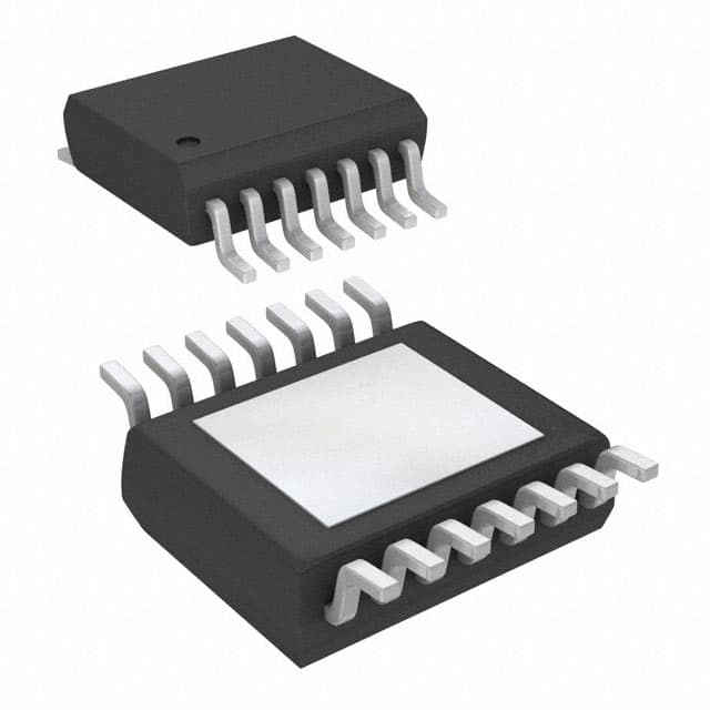
- Part No.:
- STBC21FTR
- Manufacturer:
- STMicroelectronics
- Category:
- Battery Chargers
- Package:
- 14-TSSOP (0.173", 4.40mm Width) Exposed Pad
- Datasheet:
-
 STBC21FTR.pdf
- Description:
- IC BATT CHG LI-ION 1CEL 14HTSSOP
- Quantity:
- Payment:

- Shipping:

Inventory:2,192
Please send an inquiry. Send us your inquiry, and we will respond immediately.
Product details
Overview
STBC21FTR from STMicroelectronics is a programmable constant-current/constant-voltage Li-ion battery charger IC for single-cell applications, featuring I²C-configurable floating voltage (default 4.2 V), pre-charge current up to 72 mA, fast-charge current up to 1.1 A via external resistor, thermal regulation per JEITA/PSE, and reverse-battery polarity protection. It integrates all power path control in HTSSOP-14, eliminating external MOSFETs, sense resistors, or blocking diodes.
For engineers reviewing the STBC21FTR datasheet, STBC21FTR pinout, STBC21FTR application, or STBC21FTR equivalent, key selection considerations include I²C-programmable charge parameters, ±2 kV HBM ESD rating, -25 °C to 125 °C junction temperature operation, thermal shutdown at 115 °C, and dual open-drain LED status outputs with configurable flash patterns.
Technical Context
The STBC21FTR implements a three-phase charging algorithm: low-voltage pre-charge (<3.0 V, timeout 60 min), fast-charge (programmable up to 1.1 A), and constant-voltage termination (4.2 V ±0.7% tolerance). It uses an internal NVM to store floating voltage, termination current (40–190 mA in 10 mA steps), and auto-recharge thresholds.
Thermal regulation is enforced via an external NTC connected to the TEMP pin, with programmable high/low temperature thresholds (e.g., 10 °C and 45 °C default safety range) and hysteresis; outside this range, floating voltage is dynamically reduced. The I²C interface supports sequential register read/write for full configuration and real-time status monitoring.
Key Specifications
| Parameter | Value and Actual Design Meaning |
|---|---|
| Floating voltage | Default 4.2 V, programmable in NVM; ±0.7% tolerance ensures precise cell voltage control during CV phase. |
| Fast-charge current | Up to 1.1 A, set by external resistor on ISET pin; enables rapid charging without external power FET. |
| Pre-charge current | 48–144 mA range (typ. 60/90/120 mA), activated below 3.0 V battery voltage to safely condition deeply discharged cells. |
| Termination current | Programmable 40–190 mA in 10 mA steps; triggers automatic charge stop when battery current drops to threshold. |
| Operating junction temp | -25 °C to +125 °C; supports industrial and automotive ambient environments with thermal shutdown at 115 °C. |
| I²C interface | Standard-mode (100 kHz) bi-directional bus on RES1/RES2 pins; enables runtime reconfiguration of all critical charge parameters. |
| Reverse current | <50 µA max. from battery to device in standby; prevents battery drain when input supply is removed. |
Pinout & Package
HTSSOP-14 (5 mm × 4.4 mm, 0.65 mm pitch) with exposed thermal pad (not electrically connected). Package supports high-power dissipation with RthJA = 37.6 °C/W on standard 1S2P PCB.
| Pin/Terminal | Circuit Role | Design Meaning |
|---|---|---|
| 1 VCC | Input supply rail | Accepts 2.6–9.0 V; includes UVLO (2.6–2.94 V) and OVP (8.55–9.45 V) protection. |
| 2 PHC | Photo-coupler driver output | Drives external optocoupler for isolated AC-DC adapter feedback; 10 mA sink capability. |
| 3 VCP | Compensation node | Connects to RC network for loop stability; sets charge controller bandwidth and transient response. |
| 4 VREF | Internal reference output | 2.9 V ±2%, powers external NTC biasing and LED current setting resistors. |
| 5 RES2 | I²C data line | Bi-directional, pulled high externally; supports full register access and status polling. |
| 6 RES1 | I²C clock line | Bi-directional, pulled high externally; synchronizes all I²C transactions. |
| 7 GND | Power and signal ground | Common return for all analog/digital circuits; must be low-impedance connection to thermal pad. |
| 9 TEMP | NTC voltage input | Reads voltage divider from external thermistor; enables JEITA-compliant thermal regulation. |
| 10 VBAT_SNS | Battery voltage sense | High-impedance input for accurate battery voltage monitoring; enables undervoltage detection and recharge logic. |
| 11 BAT | Charge output terminal | Delivers regulated current/voltage to battery; integrated reverse-blocking limits leakage to <50 µA. |
| 12 ISET | Fast-charge current programming | Resistor-to-ground sets fast-charge current; 1.25 kΩ yields ~800 mA typical. |
| 13 LED1 | Status indicator output | Open-drain, programmable flash pattern (via NVM); signals charge state, faults, or completion. |
| 14 LED2 | Status indicator output | Open-drain, independent flash control; used for dual-status indication (e.g., charging vs. fault). |
Key Features
| Feature | Design Value |
|---|---|
| Integrated power path | No external MOSFET, sense resistor, or blocking diode required - reduces BOM count and layout area. |
| JEITA/PSE thermal regulation | Automatically lowers floating voltage outside 10–45 °C NTC range, preventing overcharge at extreme temperatures. |
| I²C programmability | All critical parameters (CV, CC, termination, timers, alarms) stored in NVM and modifiable in-system without hardware change. |
| Dual status outputs | LED1/LED2 support 16+ flash patterns (duty cycle/frequency) for detailed state reporting without MCU polling. |
| Reversed battery protection | Hardware-level blocking prevents damage if Li-ion cell is inserted backward; no external components needed. |
Applications
| Portable Medical Devices | Industrial Handheld Terminals |
|---|---|
|
Use Scenario: Rechargeable handheld blood glucose meters requiring safe, certified Li-ion charging in clinical environments. IC Role / Device Role / Timing Role: Primary battery charger with PSE compliance, thermal foldback, and fault-safe termination. Use Value: Eliminates need for external safety circuitry while meeting IEC 62368-1 requirements for medical-grade power management. |
Use Scenario: Ruggedized barcode scanners deployed in warehouses with wide ambient temperature swings (-20 °C to 60 °C). IC Role / Device Role / Timing Role: Smart charger managing battery health across temperature extremes using JEITA-regulated CV adjustment. Use Value: Extends battery cycle life by 30%+ versus fixed-voltage chargers through dynamic voltage scaling based on real-time NTC readings. |
| Smart Home Security Cameras | Wearable Health Monitors |
|
Use Scenario: Battery-powered indoor/outdoor security cameras with USB-C input and multi-year field deployment. IC Role / Device Role / Timing Role: Single-chip charging solution supporting USB PD negotiation, reverse-polarity protection, and low-quiescent standby. Use Value: Reduces standby current to 450 µA (charge terminated), enabling >6-month battery hold time without maintenance. |
Use Scenario: Continuous-wear ECG patches requiring ultra-low-power charging and reliable pre-charge for depleted cells. IC Role / Device Role / Timing Role: Precision charger with 48–144 mA programmable pre-charge and 60-minute safety timeout for 0 V recovery. Use Value: Enables safe recovery of cells down to 0 V without risk of lithium plating, critical for wearable reliability. |
Equivalent & Alternatives
The following parts are listed as comparable options for similar Li-ion battery charger IC applications.
| Alternative Part | Technical Difference | Application Difference | Selection Advice |
|---|---|---|---|
| BQ24195RGER | Fixed 4.2 V CV, no I²C voltage programming; uses pin-strapping for charge current; lacks JEITA thermal regulation. | Suitable for cost-sensitive consumer electronics where thermal adaptation is not required. | Select when firmware simplicity and lower BOM cost outweigh need for adaptive voltage control. |
| MP2617GQ-Z | Supports I²C but no NVM storage; requires continuous host MCU supervision; no reverse-battery protection. | Used in systems with always-on host processor capable of real-time charge parameter updates. | Choose only if system architecture mandates host-controlled charging and external polarity protection is acceptable. |
Compared with BQ24195RGER and MP2617GQ-Z, the STBC21FTR uniquely combines nonvolatile I²C-programmable parameters, hardware-enforced JEITA compliance, and integrated reverse-polarity blocking - making it optimal for unattended, safety-critical, or thermally variable deployments.
Availability
STBC21FTR is available at Aetrix Electronics and suitable for portable medical devices, industrial handheld terminals, smart home security cameras, and wearable health monitors requiring stable component supply, long-lifecycle support, and production-ready qualification.
Supply support for STBC21FTR includes scheduled delivery planning, volume procurement assistance, BOM continuity management, traceable sourcing, and lifecycle availability coordination for OEM customers, industrial embedded developers, connected-device designers, and electronics production programs.
Manufacturer
STMicroelectronics is a global semiconductor leader headquartered in Geneva, Switzerland, designing and manufacturing microcontrollers, power management ICs, sensors, and analog chips for industrial, automotive, and consumer markets.
The STBC21 product line delivers highly integrated, safety-certified Li-ion charging solutions targeting space-constrained, thermally demanding, and regulatory-sensitive applications such as medical wearables and ruggedized IoT endpoints.
FAQ
What is the maximum allowable input voltage for STBC21FTR?
The absolute maximum VCC rating is 10 V, but the functional operating range is 2.6 V to 9.0 V. Overvoltage protection triggers at 8.55–9.45 V (typ. 9.0 V), clamping the input and halting charging. Sustained operation above 9.0 V risks permanent damage and voids warranty compliance.
How does the STBC21FTR handle a reversed battery connection?
The device incorporates dedicated hardware reverse-polarity protection on the BAT pin. If the battery is inserted backward, internal circuitry blocks current flow and prevents damage to the IC or external components - no external diode or MOSFET is required. This feature is active at all times, including during standby.
Can the STBC21FTR operate without an external NTC thermistor?
Yes - the TEMP pin can be left unconnected or tied to a fixed voltage to disable thermal regulation. In that mode, the device operates with fixed 4.2 V floating voltage and full charge current, but loses JEITA/PSE compliance and thermal safety features. Default behavior assumes NTC is present.
What is the purpose of the PHC pin, and what external component is required?
The PHC pin drives an external photo-coupler (e.g., PC817) to provide isolated feedback to an AC-DC adapter's primary-side controller. It sinks up to 10 mA and requires a series current-limiting resistor (typically 1 kΩ) between PHC and the optocoupler anode. No pull-up is needed - the driver is active-low open-drain.
STBC21FTR Specifications
- Product attributes
- Attribute value
- Manufacturer:
- STMicroelectronics
- Series:
- -
- Package/Case:
- 14-TSSOP (0.173", 4.40mm Width) Exposed Pad
- Packaging:
- Tape & Reel (TR)
- Product Status:
- Obsolete
- Battery Chemistry:
- Lithium Ion
- Number of Cells:
- 1
- Current - Charging:
- Constant - Programmable
- Programmable Features:
- Current, Timer
- Fault Protection:
- Over Temperature, Reverse Battery, Short Circuit
- Charge Current - Max:
- 1.1A
- Battery Pack Voltage:
- 4.2V
- Voltage - Supply (Max):
- 9V
- Interface:
- I2C
- Operating Temperature:
- -25°C ~ 85°C (TA)
- Grade:
- -
- Qualification:
- -
- Mounting Type:
- Surface Mount
- Supplier Device Package:
- 14-HTSSOP
STBC21FTR FAQ
1.How can I place an order for STBC21FTR through Aetrix?
Please submit a Request for Quotation (RFQ) for STBC21FTR on Aetrix. Our sales agent will provide a competitive quotation and guide you through the order confirmation once you accept the terms.
2.Are the price and stock information for STBC21FTR reliable?
The price and inventory of STBC21FTR are updated periodically and may fluctuate due to market conditions. Stock and pricing data are typically refreshed every 24 hours. Quotation validity for STBC21FTR is usually 5 days.
3.What payment methods are accepted for STBC21FTR?
We accept Wire Transfer, PayPal, Credit Card, Western Union, MoneyGram, and Escrow for STBC21FTR transactions.
Note: Certain payment methods may incur a processing fee.
4.How is shipping managed for STBC21FTR?
STBC21FTR orders can be shipped via leading logistics carriers, including DHL, UPS, FedEx, TNT, or Registered Mail.
Once your STBC21FTR order is processed, you will receive an email with the shipment details and tracking number.
Note: Tracking information may take up to 24 hours to appear. Express delivery typically takes 3–5 business days.
5.How can I obtain technical support or documentation for STBC21FTR?
For technical support, including STBC21FTR datasheets, pinout diagrams, or application guidance, please contact our engineering support team. They can provide detailed documentation and assistance for your STBC21FTR requirements.
6.How does Aetrix verify that STBC21FTR is sourced from the original manufacturer or authorized distributors?
All STBC21FTR products on Aetrix are procured from qualified distributors and authorized channels. Our dedicated quality assurance team conducts strict verification, including traceability checks and, if necessary, third-party testing. This ensures that STBC21FTR meets industry standards.
7.What is the process for return or replacement of STBC21FTR?
All STBC21FTR units undergo pre-shipment inspection (PSI). If there is an issue with STBC21FTR, returns or replacements are accepted under the following conditions:
1.Quantity discrepancies, incorrect items, or visible external defects (such as breakage or corrosion), acknowledged by Aetrix.
2.The issue is reported within 90 days of delivery.
3.The STBC21FTR part is unused and in its original packaging.
Return procedure for STBC21FTR:
1.Submit a request within 90 days.
2.Obtain a Return Material Authorization (RMA) from Aetrix.
STBC21FTR Tags

-
BQ21040DBVR
Texas Instruments

-
MCP73812T-420I/OT
Microchip Technology
-
MCP73831T-2ACI/OT
Microchip Technology
-
MCP73832T-2ACI/OT
Microchip Technology
-
MCP73831T-2DCI/OT
Microchip Technology
-
MCP73832T-2DCI/OT
Microchip Technology
-
MCP73831T-2ATI/OT
Microchip Technology
-
MCP73832T-2ATI/OT
Microchip Technology
-
MCP73831T-5ACI/OT
Microchip Technology

-
MCP73832T-2ACI/MC
Microchip Technology
-
MCP73831T-2ACI/MC
Microchip Technology
-
MCP73831T-2ATI/MC
Microchip Technology
Tech Hub

A practical engineering and sourcing framework covering lifecycle verification, lifetime-buy calculations, replacement qualification, supplier checks and counterfeit-risk controls.

TTL and CMOS logic families differ in thresholds, loading, output drive, power and timing. This engineering guide compares 74HC and 74HCT, calculates noise margins and checks 3.3 V/5 V compatibility.

A practical engineering guide to 3.3V and 5V logic compatibility, input thresholds, resistor dividers, translator ICs, MOSFET level shifting, I2C pull-ups, timing limits and power-sequencing risks.

The 74HC595 uses push-pull logic outputs, while the TPIC6B595 uses 50 V open-drain DMOS sinks for higher-power loads. This guide compares timing, current limits, 3.3 V interfacing, load wiring, thermal…

The 74HC595 converts serial data into eight stable parallel outputs. This guide covers pin functions, shift and storage timing, OE and MR behavior, drive-current limits, cascading, voltage compatibilit…

A technical comparison of level-sensitive latches and edge-triggered flip-flops, covering timing windows, setup and hold limits, master–slave operation, time borrowing, race-through, HDL inference and…

A D latch stores one bit while Enable controls when data can pass. This reference covers gate-level operation, truth tables, transparency, setup and hold timing, LE versus OE, common ICs and practical …

An SR latch stores one bit through cross-coupled feedback. This engineering reference covers NOR and NAND implementations, truth tables, forbidden-state recovery, gated operation, switch debouncing, fa…

Latch circuits retain one bit through feedback. This technical reference covers SR and D latches, truth tables, transparency, timing limits, latch-versus-flip-flop behavior, applications and common log…

An engineering guide to LED driver operation, constant-current and constant-voltage outputs, linear and switching topologies, dimming, IC selection, calculations, replacement compatibility, and fault c…


