
 My Inquiry
 My Account


STMicroelectronics STCF01PMR
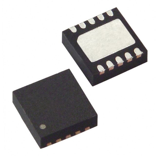
- Part No.:
- STCF01PMR
- Manufacturer:
- STMicroelectronics
- Category:
- LED Drivers
- Package:
- 10-VFDFN Exposed Pad
- Datasheet:
-
 STCF01PMR.pdf
- Description:
- IC LED DRIVER RGLTR 300MA 10DFN
- Quantity:
- Payment:

- Shipping:

Inventory:2,677
Please send an inquiry. Send us your inquiry, and we will respond immediately.
Product details
Overview
STCF01PMR from STMicroelectronics is a dedicated step-up DC-DC converter IC for driving 2–4 white LEDs in cell phone camera flash applications. It operates from 2.6V to 5.5V input, delivers up to 17V output, supports dual current levels (up to 300mA), features 1.5MHz PWM control, and provides true load disconnection via SHDN pin.
For engineers reviewing the STCF01PMR datasheet, STCF01PMR pinout, STCF01PMR application, or STCF01PMR equivalent, key selection criteria include its constant-current LED drive architecture, OVP-protected boost topology, torch/flash mode logic interface, and DFN10L (3mm × 3mm) footprint compatibility with space-constrained mobile designs.
Technical Context
The STCF01 employs current-mode PWM control with duty cycle modulation based on feedback from the FB pin, enabling precise constant-current regulation across varying LED forward voltages. Its internal 1.2A peak switch current limit and 17V overvoltage protection threshold ensure safe operation with up to four series-connected white LEDs.
Two external resistors (RHC, RLC) set high- and low-level LED currents independently; SEL pin selects between them, while SHDN pin enables shutdown (<0.5µA IQ) or forces torch mode with <200µs turn-on time - critical for burst photography timing.
Key Specifications
| Parameter | Value and Actual Design Meaning |
|---|---|
| Input Voltage Range | 2.6V to 5.5V - compatible with single-cell Li-ion battery voltage range including discharge tail. |
| Max Output Voltage | 17V - ensures sufficient headroom for four-series white LEDs (typ. 3.2V each × 4 = 12.8V). |
| Switching Frequency | 1.5MHz (±300kHz) - enables use of small 10µH inductor and ceramic capacitors for compact layout. |
| Efficiency | 90% @ 100mA, 80% @ 300mA - minimizes thermal stress and extends battery life during flash use. |
| Shutdown Current | <0.5µA - eliminates standby power drain when flash is inactive. |
| Overvoltage Threshold | 17V to 19V - hardware-enforced clamp prevents LED or IC damage under open-load or transient conditions. |
| Current Setting Accuracy | ±10% typical - achieved via resistor-ratio-based scaling with 2100 A/A and 2400 A/A multipliers. |
Pinout & Package
STCF01PMR is housed in a thermally enhanced DFN10L (3mm × 3mm, 0.5mm pitch) package with exposed thermal pad. Pin 1 is marked by a dot; top-view orientation follows JEDEC MO-229 standard.
| Pin/Terminal | Circuit Role | Design Meaning |
|---|---|---|
| PWRGND | Power ground reference | Common return for input/output capacitors and boost stage; must be low-inductance connection to minimize noise. |
| OVP | Overvoltage sense input | Monitors output voltage via resistor divider; triggers shutdown if >17V to protect LEDs and IC. |
| VI | Main supply input | Connects directly to battery; powers internal circuitry and boost switch stage. |
| HC | High-current setting | Voltage sensed at this pin sets flash-mode current via RHC; VI − VHC determines scaling. |
| LC | Low-current setting | Voltage sensed at this pin sets torch-mode current via RLC; VI − VLC determines scaling. |
| SGLGND | Logic ground reference | Separate digital ground for SEL/SHDN pins; improves noise immunity vs. PWRGND. |
| FB | Current feedback input | Measures LED current via external sense resistor; regulates output to maintain constant current. |
| SEL | Current level select | Logic-high selects HC-defined current (flash); logic-low selects LC-defined current (torch). |
| SHDN | Enable/disable control | High = shutdown (load disconnected, <0.5µA IQ); low = active (flash/torch per SEL). |
| SW | Internal switch node | Drain of integrated N-channel MOSFET; connects to inductor and Schottky diode anode. |
Key Features
| Feature | Design Value |
|---|---|
| Dual-mode constant-current control | Independent flash (up to 300mA) and torch (lower current) modes selectable via SEL pin with sub-200µs response. |
| True load disconnection | SHDN high removes all DC path from battery to LEDs - no leakage current through LEDs or sense resistor. |
| Integrated 1.2A peak switch | Eliminates need for external MOSFET; supports 10µH inductor and fits in <10mm² PCB area. |
| 17V overvoltage protection | Hardware-clamped OVP at OVP pin ensures robustness against open-circuit LED string failure. |
| Thermal shutdown with hysteresis | 145°C trip point + 15°C hysteresis prevents oscillation during sustained high-power operation. |
Applications
| Smartphone Camera Flash | Tablet Integrated Flash |
|---|---|
Use Scenario: Single- or multi-shot illumination for rear-facing camera modules in smartphones with Li-ion battery supply. IC Role / Device Role / Timing Role: Constant-current boost controller providing regulated flash current with <200µs turn-on for precise exposure timing. Use Value: Enables high-brightness flash without linear regulator losses, extending battery runtime and reducing thermal load on camera module PCB. | Use Scenario: Auxiliary lighting for front-facing video calls or document scanning in mid-size tablets. IC Role / Device Role / Timing Role: Torch-mode LED driver delivering stable low-current illumination for extended-duration use. Use Value: Maintains consistent brightness across battery discharge curve while consuming <0.5µA in standby - critical for always-on UX features. |
| Ultracompact Wearable Camera | Industrial Inspection Module |
Use Scenario: Flash illumination in body-worn action cameras where board space and thermal envelope are severely constrained. IC Role / Device Role / Timing Role: Space-optimized LED driver using DFN10L package and minimal external components (1 inductor, 2 caps, 1 diode). Use Value: Achieves full 300mA flash output in <10mm² footprint - 40% smaller than discrete boost + current-sense solutions. | Use Scenario: Machine-vision lighting for handheld barcode scanners or portable inspection tools operating from rechargeable batteries. IC Role / Device Role / Timing Role: Reliable current source tolerant of wide input voltage swing (2.6–5.5V) and ambient temperature variation (−40°C to +85°C). Use Value: Delivers repeatable LED intensity across battery life and environmental conditions - essential for consistent image capture quality. |
Equivalent & Alternatives
The following parts are listed as comparable options for similar LED boost driver applications.
| Alternative Part | Technical Difference | Application Difference | Selection Advice |
|---|---|---|---|
| MAX8630Y | Higher max output voltage (22V); requires external MOSFET; no integrated OVP comparator. | Supports >4 LED strings; less integrated protection; needs additional BOM components. | Choose when higher output voltage headroom or external switch flexibility is required. |
| TPS61310 | Fixed 1.2MHz switching frequency; no dual-current selection pins; uses I2C interface for current control. | Requires microcontroller interface; lacks direct SEL/SHDN logic control; better for programmable systems. | Choose when system already uses I2C bus and needs software-configurable LED current profiles. |
Compared with MAX8630Y and TPS61310, STCF01PMR offers the most direct hardware-controlled flash/torch implementation in the smallest footprint, with built-in OVP and true load disconnect - ideal for cost- and space-sensitive mobile camera modules where firmware overhead must be minimized.
Availability
STCF01PMR is available at Aetrix Electronics and suitable for smartphone camera flash, tablet auxiliary lighting, ultracompact wearable imaging, and industrial handheld inspection requiring stable component supply despite its obsolete status.
Supply support for STCF01PMR includes scheduled delivery planning, volume procurement assistance, BOM continuity management, traceable sourcing, and lifecycle availability coordination for OEM customers, industrial embedded developers, connected-device designers, and electronics production programs.
Manufacturer
STMicroelectronics is a global semiconductor leader headquartered in Geneva, Switzerland, designing and manufacturing analog, mixed-signal, power, and microcontroller products for automotive, industrial, and consumer markets.
The STCF01 belongs to ST's specialized LED driver product line targeting mobile imaging applications, engineered specifically for high-efficiency, low-footprint, dual-mode flash/torch operation in battery-powered camera modules.
FAQ
What is the function of the OVP pin on STCF01PMR?
The OVP pin monitors the boost converter output voltage via an external resistor divider. When the sensed voltage exceeds the internal 17V threshold, the device disables switching and clamps the output to prevent overvoltage damage to LEDs or downstream circuitry. This is a hardware-level protection independent of FB loop control.
How does the STCF01PMR achieve true load disconnection during shutdown?
When the SHDN pin is driven high, the internal power switches fully disconnect both the boost converter path and the current-sense feedback path. No DC current flows from VI to the LED string or FB resistor - verified by <0.5µA shutdown current and absence of voltage drop across the sense resistor in shutdown state.
Can STCF01PMR drive more than four white LEDs in series?
No. The 17V maximum output voltage limits operation to four typical white LEDs (3.2V–3.6V VF each). Attempting five LEDs would exceed the OVP threshold under normal operation, causing immediate shutdown. The IC is explicitly specified for 2–4 LED configurations per datasheet Section 6.
What is the role of SGLGND versus PWRGND on STCF01PMR?
SGLGND serves as the reference for digital control pins (SEL, SHDN, FB logic thresholds), isolating sensitive logic inputs from high-current power ground noise. PWRGND carries inductor return current and capacitor ripple; separating these grounds reduces coupling of switching transients into current-sense and enable logic paths.
STCF01PMR Specifications
- Product attributes
- Attribute value
- Manufacturer:
- STMicroelectronics
- Series:
- -
- Package/Case:
- 10-VFDFN Exposed Pad
- Packaging:
- Tape & Reel (TR)
- Product Status:
- Obsolete
- Type:
- DC DC Regulator
- Topology:
- Step-Up (Boost)
- Internal Switch(s):
- Yes
- Number of Outputs:
- 1
- Voltage - Supply (Min):
- 2.6V
- Voltage - Supply (Max):
- 5.5V
- Voltage - Output:
- 17V
- Current - Output / Channel:
- 300mA (Flash)
- Frequency:
- 1.5MHz
- Dimming:
- -
- Applications:
- Camera Flash
- Operating Temperature:
- -40°C ~ 85°C (TA)
- Grade:
- -
- Qualification:
- -
- Mounting Type:
- Surface Mount
- Supplier Device Package:
- 10-DFN (3x3)
STCF01PMR FAQ
1.How can I place an order for STCF01PMR through Aetrix?
Please submit a Request for Quotation (RFQ) for STCF01PMR on Aetrix. Our sales agent will provide a competitive quotation and guide you through the order confirmation once you accept the terms.
2.Are the price and stock information for STCF01PMR reliable?
The price and inventory of STCF01PMR are updated periodically and may fluctuate due to market conditions. Stock and pricing data are typically refreshed every 24 hours. Quotation validity for STCF01PMR is usually 5 days.
3.What payment methods are accepted for STCF01PMR?
We accept Wire Transfer, PayPal, Credit Card, Western Union, MoneyGram, and Escrow for STCF01PMR transactions.
Note: Certain payment methods may incur a processing fee.
4.How is shipping managed for STCF01PMR?
STCF01PMR orders can be shipped via leading logistics carriers, including DHL, UPS, FedEx, TNT, or Registered Mail.
Once your STCF01PMR order is processed, you will receive an email with the shipment details and tracking number.
Note: Tracking information may take up to 24 hours to appear. Express delivery typically takes 3–5 business days.
5.How can I obtain technical support or documentation for STCF01PMR?
For technical support, including STCF01PMR datasheets, pinout diagrams, or application guidance, please contact our engineering support team. They can provide detailed documentation and assistance for your STCF01PMR requirements.
6.How does Aetrix verify that STCF01PMR is sourced from the original manufacturer or authorized distributors?
All STCF01PMR products on Aetrix are procured from qualified distributors and authorized channels. Our dedicated quality assurance team conducts strict verification, including traceability checks and, if necessary, third-party testing. This ensures that STCF01PMR meets industry standards.
7.What is the process for return or replacement of STCF01PMR?
All STCF01PMR units undergo pre-shipment inspection (PSI). If there is an issue with STCF01PMR, returns or replacements are accepted under the following conditions:
1.Quantity discrepancies, incorrect items, or visible external defects (such as breakage or corrosion), acknowledged by Aetrix.
2.The issue is reported within 90 days of delivery.
3.The STCF01PMR part is unused and in its original packaging.
Return procedure for STCF01PMR:
1.Submit a request within 90 days.
2.Obtain a Return Material Authorization (RMA) from Aetrix.
STCF01PMR Tags

-
BCR402RE6327HTSA1
Infineon Technologies

-
BCR430UXTSA2
Infineon Technologies

-
BCR420UE6433HTMA1
Infineon Technologies
-
BCR420UE6327HTSA1
Infineon Technologies
-
BCR421UE6327HTSA1
Infineon Technologies

-
LYT1604D-TL
Power Integrations

-
HV9910CLG-G
Microchip Technology

-
CL2N8-G
Microchip Technology

-
BCR420UW6-7
Diodes Incorporated
-
BCR421UW6-7
Diodes Incorporated

-
BCR420UFD-7
Diodes Incorporated
-
BCR421UFD-7
Diodes Incorporated
Tech Hub

A practical engineering and sourcing framework covering lifecycle verification, lifetime-buy calculations, replacement qualification, supplier checks and counterfeit-risk controls.

TTL and CMOS logic families differ in thresholds, loading, output drive, power and timing. This engineering guide compares 74HC and 74HCT, calculates noise margins and checks 3.3 V/5 V compatibility.

A practical engineering guide to 3.3V and 5V logic compatibility, input thresholds, resistor dividers, translator ICs, MOSFET level shifting, I2C pull-ups, timing limits and power-sequencing risks.

The 74HC595 uses push-pull logic outputs, while the TPIC6B595 uses 50 V open-drain DMOS sinks for higher-power loads. This guide compares timing, current limits, 3.3 V interfacing, load wiring, thermal…

The 74HC595 converts serial data into eight stable parallel outputs. This guide covers pin functions, shift and storage timing, OE and MR behavior, drive-current limits, cascading, voltage compatibilit…

A technical comparison of level-sensitive latches and edge-triggered flip-flops, covering timing windows, setup and hold limits, master–slave operation, time borrowing, race-through, HDL inference and…

A D latch stores one bit while Enable controls when data can pass. This reference covers gate-level operation, truth tables, transparency, setup and hold timing, LE versus OE, common ICs and practical …

An SR latch stores one bit through cross-coupled feedback. This engineering reference covers NOR and NAND implementations, truth tables, forbidden-state recovery, gated operation, switch debouncing, fa…

Latch circuits retain one bit through feedback. This technical reference covers SR and D latches, truth tables, transparency, timing limits, latch-versus-flip-flop behavior, applications and common log…

An engineering guide to LED driver operation, constant-current and constant-voltage outputs, linear and switching topologies, dimming, IC selection, calculations, replacement compatibility, and fault c…


