
 My Inquiry
 My Account


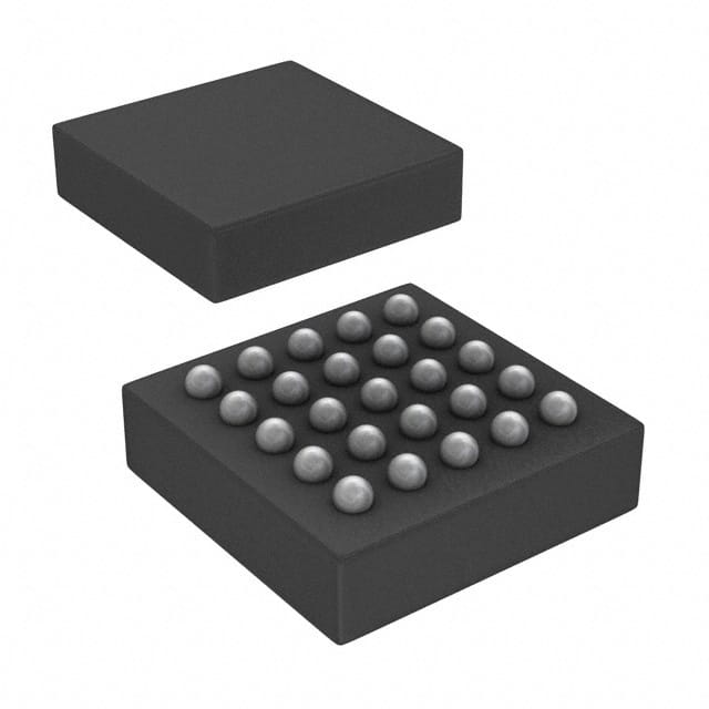
STMicroelectronics STCF03TBR
- Part No.:
- STCF03TBR
- Manufacturer:
- STMicroelectronics
- Category:
- LED Drivers
- Package:
- 25-TFBGA
- Datasheet:
-
 STCF03TBR.pdf
- Description:
- IC LED DRVR RGLTR I2C 25TFBGA
- Quantity:
- Payment:

- Shipping:

Inventory:2,589
Please send an inquiry. Send us your inquiry, and we will respond immediately.
Product details
Overview
STCF03TBR from STMicroelectronics is a high-efficiency buck-boost DC-DC LED driver IC for single-power white LED flash applications in mobile devices. It delivers up to 800 mA flash current (at 3.3–5.5 V input) and 200 mA torch current, features full I²C control, 1.8 MHz fixed-frequency PWM, and integrated LED overtemperature/short/open protection. Used in smartphone camera strobes with NTC-based thermal management.
For engineers reviewing the STCF03TBR datasheet, STCF03TBR pinout, STCF03TBR application, or STCF03TBR equivalent, key selection criteria include its TFBGA25 (3 × 3 mm) package, I²C-programmable flash/torch dimming (16 exponential steps), dual-mode operation (flash/torch), auxiliary red LED output, and battery-voltage-agnostic buck-boost regulation from 2.7 V to 5.5 V.
Technical Context
The STCF03TBR implements a synchronous buck-boost topology that automatically transitions between buck, boost, and buck-boost modes based on LED forward voltage versus battery voltage - ensuring stable 800 mA flash current across 2.7–5.5 V input. Regulation relies on dual feedback (FB1/FB2) sensing via external RFL (0.27 Ω) and RTR (1.8 Ω) resistors to maintain precise current accuracy (±10%).
Its I²C interface (SCL/SDA) supports four slave addresses via ADD pin, enabling multi-device configuration. Functional modes - shutdown, ready + auxiliary LED, flash, and torch - are controlled via register writes (e.g., PWR_ON, TRIG_EN, F_RUN) and hardware pins (TRIG, TMSK, ATN), with soft/hard flash triggering and digitally programmable safety time-out.
Key Specifications
| Parameter | Value and Actual Design Meaning |
|---|---|
| Topology | Synchronous buck-boost converter - maintains regulated LED current regardless of battery sag or LED VF variation. |
| Max Flash Current | 800 mA at VIN = 3.3–5.5 V - sufficient for high-intensity camera flash in smartphones. |
| Torch Current Range | 15–200 mA - adjustable via I²C for video recording illumination with low power draw. |
| Switching Frequency | 1.8 MHz typical - enables compact external components (4.7 µH inductor, 0603 capacitors). |
| Efficiency | 87% (chip only), 76% (full application) at 800 mA flash - minimizes thermal load and extends battery life. |
| I²C Interface | Standard two-wire bus with 4 selectable addresses - reduces PCB routing complexity and supports multi-LED systems. |
| Protection Features | LED open/short detection, chip overtemperature (140 °C), NTC-based LED overtemperature, programmable flash timeout - ensures system reliability under fault conditions. |
Pinout & Package
STCF03TBR is housed in a 25-ball TFBGA package (3 × 3 mm, 0.5 mm pitch) with an exposed thermal pad connected to PGND. Pin functions are validated per ST's official pin description table (Doc ID 13169 Rev 7, Table 2) and bottom-view layout (Figure 2).
| Pin/Terminal | Circuit Role | Design Meaning |
|---|---|---|
| PVBAT / VBAT | Main power supply input | Accepts 2.7–5.5 V Li-ion battery; powers internal circuitry and high-current switching path. |
| VLX1A / VLX1B / VLX2 | Inductor connection terminals | Interface with external 4.7 µH coupled inductor; VLX1A/VLX1B form primary winding, VLX2 is secondary. |
| VOUT | LED anode output | Delivers regulated current to flash LED cathode via RFL; voltage range 2.5–5.3 V. |
| FB1 / FB2 / FB2S | Current-sense feedback inputs | FB1 monitors total LED current (ILED × (RFL + RTR)); FB2/FB2S sense RFL-only drop for precision regulation. |
| SCL / SDA | I²C serial interface | Enable full digital control of mode, dimming, timeout, and status readback; require external 3.0 V pull-ups. |
| TRIG | Hardware flash trigger | Active-high input that initiates flash when ANDed with TRIG_EN register bit - supports precise timing independent of I²C latency. |
| TMSK | RF transmission mask | Active-high signal that forces immediate flash current reduction during cellular TX - prioritizes RF power over illumination. |
| ATN | Attention interrupt output | Open-drain active-low flag signaling faults (LED open/short, overtemp, OVP) to host processor. |
| AUXL | Auxiliary red LED driver | Provides 0–20 mA current for status indicator (e.g., recording light); dimmable via AUXI/AUXT registers. |
| NTC | External thermistor input | Connects to 100 kΩ NTC (e.g., Murata NCP21WF104J03RA) for LED temperature monitoring and thermal derating. |
| ADD | I²C address select | Binary input (GND/VIN/SDA/SCL) sets one of four slave addresses - enables multiple STCF03TBRs on same bus. |
| PGND / GND | Power and signal ground | Separate PGND (pins E1/E5/C3/D3) and GND (pin E2) minimize noise coupling into sensitive analog feedback paths. |
Key Features
| Feature | Design Value |
|---|---|
| Dual-mode LED current control | Independent 16-step exponential dimming for flash (60–800 mA) and torch (15–200 mA) - enables consistent brightness scaling across intensity ranges. |
| Hardware-triggered flash | TRIG pin + TRIG_EN register enable sub-microsecond flash activation - eliminates I²C bus contention during critical capture timing. |
| RF-aware current throttling | TMSK pin forces immediate flash current reduction during cellular transmission - preserves battery headroom for RF PA without software intervention. |
| Programmable flash safety timeout | Digitally settable 0.5–8 s timeout (FTIM_0–3 registers) - prevents LED damage from erroneous host commands or firmware hangs. |
| Integrated fault diagnostics | ATN pin asserts on LED open/short, chip overtemperature (140 °C), or output overvoltage (5.3 V) - enables real-time system-level error handling. |
| Thermal-aware LED protection | NTC input supports external 100 kΩ thermistor; enables dynamic flash current derating based on LED junction temperature - extends LED lifetime. |
Applications
| Smartphone Camera Flash | Digital Still Camera Strobe |
|---|---|
|
Use Scenario: High-intensity illumination for low-light photo capture in compact mobile handsets with single-cell Li-ion batteries. IC Role / Device Role / Timing Role: Primary flash LED driver providing 800 mA regulated current with <2 ms LED rise time and hardware-triggered activation. Use Value: Enables consistent flash output despite battery voltage decay from 4.2 V to 3.0 V, while maintaining <10% current tolerance via dual feedback sensing. |
Use Scenario: Synchronized strobe lighting for DSLR/mirrorless camera accessories requiring precise flash duration and intensity control. IC Role / Device Role / Timing Role: Standalone flash controller interfacing with camera MCU via I²C to configure flash mode, dimming, and safety timeout. Use Value: Eliminates need for discrete MOSFETs and op-amps by integrating buck-boost regulation, current sensing, and protection - reducing BOM count by ≥7 components. |
| Video Recording Torch Light | Mobile Device Status Indicator |
|
Use Scenario: Continuous low-power illumination during HD video capture in smartphones and tablets. IC Role / Device Role / Timing Role: Torch-mode LED driver delivering 200 mA with 16-step exponential dimming and thermal foldback. Use Value: Provides flicker-free, color-stable illumination with <1.8 mA quiescent current in ready mode - extending runtime during extended video sessions. |
Use Scenario: Dual-color status feedback (white flash + red auxiliary) in portable medical or industrial handheld devices. IC Role / Device Role / Timing Role: Auxiliary LED driver (AUXL) supplying 0–20 mA to red indicator LED, independently dimmable via I²C. Use Value: Replaces discrete LED driver IC or GPIO + current-limiting resistor - saves PCB area and enables synchronized blink patterns with flash events. |
Equivalent & Alternatives
The following parts are listed as comparable options for similar high-efficiency LED flash driver applications.
| Alternative Part | Technical Difference | Application Difference | Selection Advice |
|---|---|---|---|
| LM3644TME/NOPB | Single-inductor buck-boost architecture; 1.5 MHz switching; max 1.5 A flash current; no NTC input; uses single FB pin. | Lacks integrated NTC-based LED thermal protection and separate torch/flash dimming registers - requires external thermal management. | Preferred where higher peak current (>800 mA) is needed and thermal monitoring is handled externally or omitted. |
| TPS61310DSKR | Boost-only topology; 2.5 MHz switching; max 1.2 A flash current; analog/digital dimming; no I²C interface - uses EN/TRIG pins only. | No register-based configuration or fault reporting; limited to fixed or GPIO-controlled modes - less flexible for complex UI-driven flash behavior. | Chosen when system-level simplicity and minimal firmware overhead outweigh need for diagnostics and programmability. |
Compared with LM3644TME/NOPB and TPS61310DSKR, STCF03TBR uniquely combines I²C configurability, NTC-based thermal protection, and hardware-triggered flash in a 3 × 3 mm TFBGA - making it optimal for space-constrained, thermally demanding smartphone designs requiring robust fault handling.
Availability
STCF03TBR is available at Aetrix Electronics and suitable for smartphone camera modules, digital still camera strobes, mobile video torch systems, and portable medical imaging devices requiring stable component supply and long-term lifecycle support.
Supply support for STCF03TBR includes scheduled delivery planning, volume procurement assistance, BOM continuity management, traceable sourcing, and lifecycle availability coordination for OEM customers, industrial embedded developers, connected-device designers, and electronics production programs.
Manufacturer
STMicroelectronics is a global semiconductor leader headquartered in Geneva, Switzerland, designing and manufacturing microcontrollers, power management ICs, sensors, and analog products for automotive, industrial, and consumer markets.
The STCF03 belongs to ST's LED lighting driver product line, engineered specifically for high-efficiency, thermally robust flash illumination in battery-powered portable electronics - emphasizing integration, protection, and I²C programmability.
FAQ
What is the maximum flash current supported by STCF03TBR at 3.0 V input?
At 3.0 V input, STCF03TBR delivers up to 600 mA flash current - verified per datasheet Table 6 (Flash mode for VI = 2.7 V to 3.3 V). This limitation arises from reduced headroom for boost operation; performance recovers to 800 mA above 3.3 V input due to improved efficiency and duty-cycle margin.
How does the TMSK pin interact with flash current regulation?
The TMSK pin is a dedicated hardware input that, when asserted high, forces immediate reduction of flash current to a preconfigured safe level (typically ≤200 mA) - independent of I²C register state. This allows concurrent RF transmission without software intervention, preserving battery capacity for the power amplifier.
Can STCF03TBR drive LEDs with forward voltages exceeding 5.3 V?
No. The STCF03TBR's regulated output voltage range is strictly 2.5–5.3 V (Table 6), enforced by internal OVP circuitry (5.3 V threshold, 0.3 V hysteresis). Driving LEDs with VF > 5.3 V would trigger overvoltage protection and disable output - requiring external boost stage or alternative driver.
Is the auxiliary LED output (AUXL) capable of driving standard 20 mA red LEDs directly?
Yes. AUXL provides 0–20 mA sink current with ±10% accuracy (per datasheet Table 6), supporting common 2 VF red LEDs at 3.3 V supply. No external current-setting resistor is required - current is digitally programmed via AUXI_0–3 registers and scaled exponentially for smooth dimming.
STCF03TBR Specifications
- Product attributes
- Attribute value
- Manufacturer:
- STMicroelectronics
- Series:
- -
- Package/Case:
- 25-TFBGA
- Packaging:
- Tape & Reel (TR)
- Product Status:
- Obsolete
- Type:
- DC DC Regulator
- Topology:
- Step-Down (Buck), Step-Up (Boost)
- Internal Switch(s):
- Yes
- Number of Outputs:
- 1
- Voltage - Supply (Min):
- 2.7V
- Voltage - Supply (Max):
- 5.5V
- Voltage - Output:
- 2.5V ~ 5.3V
- Current - Output / Channel:
- 800mA (Flash)
- Frequency:
- 1.8MHz
- Dimming:
- I2C
- Applications:
- Camera Flash
- Operating Temperature:
- -40°C ~ 85°C (TA)
- Grade:
- -
- Qualification:
- -
- Mounting Type:
- Surface Mount
- Supplier Device Package:
- 25-TFBGA (3x3)
STCF03TBR FAQ
1.How can I place an order for STCF03TBR through Aetrix?
Please submit a Request for Quotation (RFQ) for STCF03TBR on Aetrix. Our sales agent will provide a competitive quotation and guide you through the order confirmation once you accept the terms.
2.Are the price and stock information for STCF03TBR reliable?
The price and inventory of STCF03TBR are updated periodically and may fluctuate due to market conditions. Stock and pricing data are typically refreshed every 24 hours. Quotation validity for STCF03TBR is usually 5 days.
3.What payment methods are accepted for STCF03TBR?
We accept Wire Transfer, PayPal, Credit Card, Western Union, MoneyGram, and Escrow for STCF03TBR transactions.
Note: Certain payment methods may incur a processing fee.
4.How is shipping managed for STCF03TBR?
STCF03TBR orders can be shipped via leading logistics carriers, including DHL, UPS, FedEx, TNT, or Registered Mail.
Once your STCF03TBR order is processed, you will receive an email with the shipment details and tracking number.
Note: Tracking information may take up to 24 hours to appear. Express delivery typically takes 3–5 business days.
5.How can I obtain technical support or documentation for STCF03TBR?
For technical support, including STCF03TBR datasheets, pinout diagrams, or application guidance, please contact our engineering support team. They can provide detailed documentation and assistance for your STCF03TBR requirements.
6.How does Aetrix verify that STCF03TBR is sourced from the original manufacturer or authorized distributors?
All STCF03TBR products on Aetrix are procured from qualified distributors and authorized channels. Our dedicated quality assurance team conducts strict verification, including traceability checks and, if necessary, third-party testing. This ensures that STCF03TBR meets industry standards.
7.What is the process for return or replacement of STCF03TBR?
All STCF03TBR units undergo pre-shipment inspection (PSI). If there is an issue with STCF03TBR, returns or replacements are accepted under the following conditions:
1.Quantity discrepancies, incorrect items, or visible external defects (such as breakage or corrosion), acknowledged by Aetrix.
2.The issue is reported within 90 days of delivery.
3.The STCF03TBR part is unused and in its original packaging.
Return procedure for STCF03TBR:
1.Submit a request within 90 days.
2.Obtain a Return Material Authorization (RMA) from Aetrix.
STCF03TBR Tags

-
BCR402RE6327HTSA1
Infineon Technologies

-
BCR430UXTSA2
Infineon Technologies

-
BCR420UE6433HTMA1
Infineon Technologies
-
BCR420UE6327HTSA1
Infineon Technologies
-
BCR421UE6327HTSA1
Infineon Technologies

-
LYT1604D-TL
Power Integrations

-
HV9910CLG-G
Microchip Technology

-
CL2N8-G
Microchip Technology

-
BCR420UW6-7
Diodes Incorporated
-
BCR421UW6-7
Diodes Incorporated

-
BCR420UFD-7
Diodes Incorporated
-
BCR421UFD-7
Diodes Incorporated
Tech Hub

A practical engineering and sourcing framework covering lifecycle verification, lifetime-buy calculations, replacement qualification, supplier checks and counterfeit-risk controls.

TTL and CMOS logic families differ in thresholds, loading, output drive, power and timing. This engineering guide compares 74HC and 74HCT, calculates noise margins and checks 3.3 V/5 V compatibility.

A practical engineering guide to 3.3V and 5V logic compatibility, input thresholds, resistor dividers, translator ICs, MOSFET level shifting, I2C pull-ups, timing limits and power-sequencing risks.

The 74HC595 uses push-pull logic outputs, while the TPIC6B595 uses 50 V open-drain DMOS sinks for higher-power loads. This guide compares timing, current limits, 3.3 V interfacing, load wiring, thermal…

The 74HC595 converts serial data into eight stable parallel outputs. This guide covers pin functions, shift and storage timing, OE and MR behavior, drive-current limits, cascading, voltage compatibilit…

A technical comparison of level-sensitive latches and edge-triggered flip-flops, covering timing windows, setup and hold limits, master–slave operation, time borrowing, race-through, HDL inference and…

A D latch stores one bit while Enable controls when data can pass. This reference covers gate-level operation, truth tables, transparency, setup and hold timing, LE versus OE, common ICs and practical …

An SR latch stores one bit through cross-coupled feedback. This engineering reference covers NOR and NAND implementations, truth tables, forbidden-state recovery, gated operation, switch debouncing, fa…

Latch circuits retain one bit through feedback. This technical reference covers SR and D latches, truth tables, transparency, timing limits, latch-versus-flip-flop behavior, applications and common log…

An engineering guide to LED driver operation, constant-current and constant-voltage outputs, linear and switching topologies, dimming, IC selection, calculations, replacement compatibility, and fault c…


