
 My Inquiry
 My Account


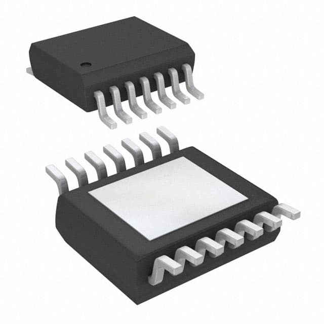
STMicroelectronics STEF01FTR
- Part No.:
- STEF01FTR
- Manufacturer:
- STMicroelectronics
- Category:
- Current Regulation/Management
- Package:
- 14-TSSOP (0.173", 4.40mm Width) Exposed Pad
- Datasheet:
-
 STEF01FTR.pdf
- Description:
- IC ELECTRONIC FUSE 5% 14HTSSOP
- Quantity:
- Payment:

- Shipping:

Inventory:1,550
Please send an inquiry. Send us your inquiry, and we will respond immediately.
Product details
Overview
STEF01FTR from STMicroelectronics is a fully programmable universal electronic fuse in HTSSOP14 package, designed for series insertion in DC power rails (8–48 V) to monitor and protect against overcurrent, overvoltage, and thermal faults. It delivers 4 A continuous current with 30 mΩ typical RDS(on), adjustable output clamp (10–52 V), and supports hot-swap operation in telecom and industrial power modules.
For engineers reviewing the STEF01FTR datasheet, STEF01FTR pinout, STEF01FTR application, or STEF01FTR equivalent, key selection considerations include programmable UVLO threshold (8–45 V), dual-mode thermal protection (latch/auto-retry), external reverse-current MOSFET gate drive, soft-start timing control via dv/dt capacitor, and Power Good flag signaling.
Technical Context
The STEF01FTR integrates an N-channel power MOSFET with precision current sensing using a Sense FET architecture, enabling foldback current limiting (1.5 A short-circuit, 4 A overload) based on external RLimit. Its overvoltage clamp circuit operates independently of input voltage slew rate and responds within microseconds when VIN exceeds the user-set VClamp threshold.
Thermal management combines two coordinated protections: maximum power dissipation limiting (fast-acting, auto-retry only) and junction temperature shutdown (175 °C, configurable latch/auto-retry via Auto pin). The EN/Fault pin serves as tri-state interface-enabling device control, fault signaling (1.4 V intermediate state for thermal latch, 0 V for auto-retry), and inter-device synchronization.
Key Specifications
| Parameter | Value and Actual Design Meaning |
|---|---|
| Input Voltage Range | 8–48 V operating; enables use across 12 V, 24 V, and 48 V industrial/telecom rails |
| Continuous Current | 4 A typ.; supports medium-power loads without external heatsinking on 2-layer PCB |
| RDS(on) | 30 mΩ typ. at TJ = 25 °C; limits conduction loss to ≤384 mW at 4 A |
| Output Clamp Range | Adjustable 10–52 V via resistor divider on Vclamp pin; protects downstream 24 V or 48 V circuits |
| UVLO Threshold | Programmable 8–45 V via resistor divider on UVLO pin; prevents startup under brownout |
| Soft-Start Time | Default 3 ms (no Cdv/dt); extended up to >100 ms with external capacitor for high-COUT hot-swap |
| Thermal Shutdown | 175 °C typ., with 25 °C hysteresis in auto-retry mode; ensures safe recovery after overload |
| Power Good Flag | Open-drain PG pin asserts high when VOUT ≥ VCC − 1 V; enables system-level power sequencing |
Pinout & Package
HTSSOP14 package with exposed pad connected internally to VCC; 4.4 mm × 5 mm footprint, 0.65 mm pitch, suitable for automated assembly and thermal relief via PCB copper pour under exposed pad.
| Pin/Terminal | Circuit Role | Design Meaning |
|---|---|---|
| 1 (UVLO) | UVLO threshold setting input | Resistor divider sets turn-on voltage (8–45 V); floating defaults to 14.5 V |
| 2 (dv/dt) | Soft-start ramp control | External capacitor extends turn-on time; open defaults to ~3 ms ramp |
| 3 (GND) | Signal and power ground reference | Must be low-impedance connection to minimize sensing error and noise coupling |
| 4 (Auto) | Thermal protection mode select | GND = auto-retry; floating/high = latched shutdown |
| 5 (Vclamp) | Overvoltage clamp threshold input | Resistor divider sets clamp level (10–52 V); floating defaults to 28 V |
| 6–9 (VOUT) | Power output terminals | All four pins must be shorted together on PCB to handle 4 A with minimal IR drop |
| 10 (I-Limit) | Overload current limit set point | Resistor to VOUT programs ILIM (3.2–4.8 A) and ISHORT (1.5 A) |
| 11 (Vg) | External MOSFET gate driver | 9.5 V typical gate drive; enables reverse-current blocking with external N-MOS |
| 12 (En/Fault) | Enable input / fault status output | Tri-state: HI = enable, LO = disable, 1.4 V = thermal latch fault, 0 V = auto-retry fault |
| 13 (PG) | Power Good flag | Open-drain output pulled high externally; asserts when VOUT ≥ VCC − 1 V |
| 14 (VCC) | Main power input | Connects to exposed pad; internal drain node of power MOSFET |
| Exposed Pad | Thermal and electrical connection to VCC | Required for thermal performance (RthJC = 4 °C/W); must be soldered to large copper area |
Key Features
| Feature | Design Value |
|---|---|
| Programmable Overvoltage Clamp | 10–52 V range via external resistor divider; prevents damage to downstream 24 V/48 V ICs during transients |
| Dual-Mode Thermal Protection | Selectable latch (manual reset) or auto-retry (self-recovering) behavior via single Auto pin connection |
| Integrated Power Limiting | Real-time power dissipation monitoring shuts down FET before die overheats-faster than thermal shutdown alone |
| Reverse-Current Blocking Support | Vg pin drives external N-MOS gate to block backfeed during hot-swap or rail collapse |
| Configurable Soft-Start | Capacitor-adjustable dv/dt controls inrush into large capacitive loads without external controllers |
| System-Level Fault Coordination | EN/Fault pin allows daisy-chaining multiple STEF01FTRs for synchronized shutdown during thermal events |
Applications
| Hot-Swap Power Distribution | Industrial Alarm & Lighting Control |
|---|---|
Use Scenario: Inserting a powered blade into a live backplane without disrupting other slots or causing bus voltage sag. IC Role / Device Role / Timing Role: Series e-fuse providing controlled ramp-up, current limiting, and fast disconnect on overcurrent. Use Value: Enables zero-downtime maintenance with <3 ms soft-start and foldback current limiting that sustains 1.5 A during short-circuit until safe shutdown. | Use Scenario: Protecting 24 V LED drivers and alarm sensors in factory automation panels subject to cable faults and ESD. IC Role / Device Role / Timing Role: Primary overcurrent and overvoltage protector on distributed 24 V supply rails. Use Value: Adjustable 28 V clamp and 4 A current limit prevent damage to sensitive lighting ICs while supporting UL2367 recognition for safety compliance. |
| Telecom DC Power Modules | Distributed Power Systems |
Use Scenario: Secondary-side protection in 48 V telecom rectifiers feeding multiple load cards with varying capacitance. IC Role / Device Role / Timing Role: Programmable e-fuse ensuring stable startup into high-COUT loads and clamping surges above 52 V. Use Value: External Cdv/dt tuning extends soft-start beyond 100 ms, avoiding false trips during bulk capacitor charging. | Use Scenario: Isolating branch circuits in redundant 12–48 V power architectures where fault containment is critical. IC Role / Device Role / Timing Role: Intelligent fuse with Power Good flag and inter-device EN/Fault coordination. Use Value: PG signal enables upstream controller to verify rail integrity; daisy-chained fault pins ensure cascaded shutdown of entire subsystem on single fault. |
Equivalent & Alternatives
The following parts are listed as comparable options for similar electronic fuse applications.
| Alternative Part | Technical Difference | Application Difference | Selection Advice |
|---|---|---|---|
| TPS25982L (Texas Instruments) | Higher 6 A continuous rating; integrated current sense amplifier; no external Vg driver for reverse-blocking MOSFET | Requires external circuitry for reverse-current blocking; better suited for current-monitoring telemetry than pure protection | Choose when precise current measurement and telemetry are required over reverse-blocking capability |
| MP5418 (Monolithic Power Systems) | Lower 3.6 A rating; fixed 12 V UVLO; no programmable overvoltage clamp; smaller QFN-16 package | Limited to fixed-rail systems; lacks adjustable clamp and soft-start timing control | Choose for cost-sensitive, space-constrained 12 V applications where full programmability is unnecessary |
Compared with TPS25982L and MP5418, STEF01FTR uniquely combines adjustable overvoltage clamp (10–52 V), dedicated Vg driver for reverse-current blocking, and dual-mode thermal protection-all in a single HTSSOP14 package validated to UL2367 and IEC 62368-1.
Availability
STEF01FTR is available at Aetrix Electronics and suitable for hot-swap power distribution, industrial alarm/lighting systems, and telecom power modules requiring stable component supply, long-term lifecycle support, and safety-certified protection ICs.
Supply support for STEF01FTR includes scheduled delivery planning, volume procurement assistance, BOM continuity management, traceable sourcing, and lifecycle availability coordination for OEM customers, industrial embedded developers, connected-device designers, and electronics production programs.
Manufacturer
STMicroelectronics is a global semiconductor leader headquartered in Geneva, specializing in power management, analog, microcontrollers, and automotive ICs with strong industrial and telecom focus.
The STEF01 product line delivers programmable electronic fuses for DC power rail protection-designed specifically for hot-swap, distributed power, and safety-critical industrial systems demanding configurability, reliability, and regulatory compliance.
FAQ
What is the minimum RLimit resistor value supported for reliable current limiting?
The RLimit resistor must be ≥8 Ω per datasheet Table 3. Using values below 8 Ω risks malfunction of the current-limiting circuit and potential device damage due to uncontrolled sense-FET biasing. Typical design uses 11–22 Ω to achieve 3.2–4.8 A overload limit while maintaining stability across temperature.
How does the STEF01FTR behave during a short-circuit event?
Upon short-circuit detection, it first enters foldback current limiting (1.5 A typ. with RLimit = 22 Ω), then triggers maximum power protection if dissipation exceeds safe limits, followed by thermal shutdown at 175 °C. Fault status appears on EN/Fault pin as 0 V (auto-retry) or 1.4 V (latch), depending on Auto pin configuration.
Can the Vclamp function protect against fast transients like ESD or lightning surges?
No-the Vclamp circuit responds to sustained overvoltage conditions (ms-scale), not nanosecond transients. For ESD (2 kV HBM) and surge immunity, external TVS diodes remain essential. The Vclamp is intended for slower overvoltage events such as regulator failure or incorrect supply connection.
Is the exposed pad electrically isolated or connected internally?
The exposed pad is electrically connected to VCC (pin 14) and forms the internal drain node of the power MOSFET. It must be soldered to a PCB copper pour tied to the main 8–48 V rail-not left floating-to ensure both thermal performance (RthJC = 4 °C/W) and correct device operation.
STEF01FTR Specifications
- Product attributes
- Attribute value
- Manufacturer:
- STMicroelectronics
- Series:
- -
- Package/Case:
- 14-TSSOP (0.173", 4.40mm Width) Exposed Pad
- Packaging:
- Tape & Reel (TR)
- Product Status:
- Active
- Function:
- Electronic Fuse
- Sensing Method:
- -
- Accuracy:
- ±5%
- Voltage - Input:
- 8V ~ 48V
- Current - Output:
- 4A
- Operating Temperature:
- -40°C ~ 125°C (TJ)
- Grade:
- -
- Qualification:
- -
- Mounting Type:
- Surface Mount
- Supplier Device Package:
- 14-HTSSOP
STEF01FTR FAQ
1.How can I place an order for STEF01FTR through Aetrix?
Please submit a Request for Quotation (RFQ) for STEF01FTR on Aetrix. Our sales agent will provide a competitive quotation and guide you through the order confirmation once you accept the terms.
2.Are the price and stock information for STEF01FTR reliable?
The price and inventory of STEF01FTR are updated periodically and may fluctuate due to market conditions. Stock and pricing data are typically refreshed every 24 hours. Quotation validity for STEF01FTR is usually 5 days.
3.What payment methods are accepted for STEF01FTR?
We accept Wire Transfer, PayPal, Credit Card, Western Union, MoneyGram, and Escrow for STEF01FTR transactions.
Note: Certain payment methods may incur a processing fee.
4.How is shipping managed for STEF01FTR?
STEF01FTR orders can be shipped via leading logistics carriers, including DHL, UPS, FedEx, TNT, or Registered Mail.
Once your STEF01FTR order is processed, you will receive an email with the shipment details and tracking number.
Note: Tracking information may take up to 24 hours to appear. Express delivery typically takes 3–5 business days.
5.How can I obtain technical support or documentation for STEF01FTR?
For technical support, including STEF01FTR datasheets, pinout diagrams, or application guidance, please contact our engineering support team. They can provide detailed documentation and assistance for your STEF01FTR requirements.
6.How does Aetrix verify that STEF01FTR is sourced from the original manufacturer or authorized distributors?
All STEF01FTR products on Aetrix are procured from qualified distributors and authorized channels. Our dedicated quality assurance team conducts strict verification, including traceability checks and, if necessary, third-party testing. This ensures that STEF01FTR meets industry standards.
7.What is the process for return or replacement of STEF01FTR?
All STEF01FTR units undergo pre-shipment inspection (PSI). If there is an issue with STEF01FTR, returns or replacements are accepted under the following conditions:
1.Quantity discrepancies, incorrect items, or visible external defects (such as breakage or corrosion), acknowledged by Aetrix.
2.The issue is reported within 90 days of delivery.
3.The STEF01FTR part is unused and in its original packaging.
Return procedure for STEF01FTR:
1.Submit a request within 90 days.
2.Obtain a Return Material Authorization (RMA) from Aetrix.
STEF01FTR Tags
.jpg)
-
PSSI2021SAY,115
Nexperia USA Inc.

-
BCR401RE6327HTSA1
Infineon Technologies

-
INA199B2DCKR
Texas Instruments
-
INA199A1DCKR
Texas Instruments
-
INA199B1DCKR
Texas Instruments
-
NSI45015WT1G
onsemi
-
NSI45020T1G
onsemi
-
NSI45030AT1G
onsemi
-
NSI45025AT1G
onsemi
-
NSI45020AT1G
onsemi
-
NSI50010YT1G
onsemi
-
LM334Z/NOPB
Texas Instruments
Tech Hub

Jumper cables guide covering safe connection order, red and black clamp placement, final ground connection, cable gauge, length, clamp quality, copper vs CCA cables, jump starter comparison and battery…

LDO regulator guide covering low dropout voltage, power dissipation, thermal design, PSRR, output noise, capacitor stability, adjustable LDO circuits, LDO vs buck converter and datasheet selection chec…

Conditional Access Module guide covering CAM meaning, CI/CI+ interface, smart card authorization, DVB security workflow, TV and set-top box compatibility, internal electronics, ESD protection, connecto…

Guide to electronic component obsolescence covering EOL risk, PCN/PDN notices, last-time buy planning, replacement options, form-fit-function validation, counterfeit risk and BOM lifecycle management.

18650 battery guide covering lithium-ion cell basics, 3.6V/3.7V voltage, 4.2V charging, mAh and Wh capacity, protected cells, chargers, BMS, series-parallel packs, holders, welding and sourcing checks.…

Hall effect sensor guide covering working principle, linear and digital sensors, Arduino circuits, current sensing, speed detection, automotive applications, A3144 examples, signal filtering and datash…

Product Change Notification guide for electronic components, covering PCN meaning, PCN vs PDN/EOL, common change types, risk levels, form-fit-function review, engineering validation, BOM control, LTB/L…

A practical guide to blend door actuators, covering HVAC function, symptoms, location, AC and heater issues, reset and calibration, replacement cost, electrical diagnosis, compatibility checks, and rep…

Engineering guide to Raspberry Pi alternatives, covering chip-level differences, Orange Pi, ROCK, Jetson, Banana Pi, NanoPi, Compute Module, Pico, GPIO, camera, HAT compatibility, and replacement risks…

Engineering guide to dynamic load response testing for high-current buck converters, covering load step setup, slew rate, Vcore undershoot, overshoot, recovery time, probe location, output capacitors a…


