
 My Inquiry
 My Account


STMicroelectronics STEF12PUR
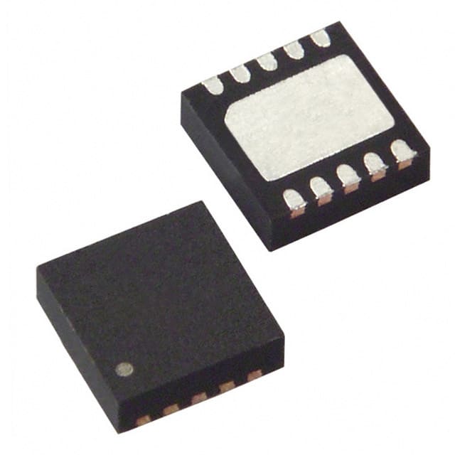
- Part No.:
- STEF12PUR
- Manufacturer:
- STMicroelectronics
- Category:
- Current Regulation/Management
- Package:
- 10-VFDFN Exposed Pad
- Datasheet:
-
 STEF12PUR.pdf
- Description:
- IC ELECTRONIC FUSE 10DFN
- Quantity:
- Payment:

- Shipping:

Inventory:3,830
Please send an inquiry. Send us your inquiry, and we will respond immediately.
Product details
Overview
STEF12PUR from STMicroelectronics is a 12 V electronic fuse (eFuse) with integrated N-channel power MOSFET, designed for series protection of 12 V rails in storage and consumer electronics. It delivers 3.6 A continuous current, 53 mΩ typical on-resistance, 15 V output clamping, thermal latch at 165 °C, and controlled dv/dt ramp-up - enabling safe inrush management in HDD/SSD power paths.
For engineers reviewing the STEF12PUR datasheet, STEF12PUR pinout, STEF12PUR application, or STEF12PUR equivalent, key selection criteria include programmable current limiting via external resistor, tri-state Enable/Fault signaling for thermal fault reporting and coordinated shutdown, UL2367 recognition, DFN10 (3×3 mm) package thermal performance (RthJA = 52.7 °C/W), and compatibility with 12 V automotive-grade supply monitoring.
Technical Context
The STEF12PUR implements a precision current-sense architecture using an internal N-channel sense FET with fixed ratio to monitor load current and enforce programmable short-circuit (3.3–5.5 A) and overload (4.4 A) limits via external RLimit. Its dv/dt control circuit-configurable with external capacitor-delivers adjustable output voltage ramp time (0.5–2.6 ms) and 350 µs enable delay.
Thermal protection operates as a latched shutdown at 165 °C, signaled via intermediate voltage (0.82–1.95 V) on the bi-directional En/Fault pin; undervoltage lockout (7.7–9.3 V) and overvoltage clamping (13.8–16.2 V) provide rail integrity across -40 °C to 125 °C junction temperature range.
Key Specifications
| Parameter | Value and Actual Design Meaning |
|---|---|
| Continuous current | 3.6 A at 25 °C with 0.5 in² copper pad - defines max sustained load without derating under standard PCB layout. |
| N-channel RDS(on) | 53 mΩ typ - determines I²R loss (≈230 mW at 3 A) and output voltage drop during normal operation. |
| Output clamp voltage | 15 V typ - limits downstream component stress during input overvoltage transients up to 18 V. |
| Undervoltage lockout | 8.5 V typ with 0.8 V hysteresis - prevents erratic operation during brown-out and ensures clean startup above rail stability threshold. |
| Thermal latch threshold | 165 °C typ - triggers irreversible shutdown until reset, protecting against sustained overload-induced MOSFET failure. |
| Enable/Fault logic levels | VIL = 0.58 V max, VIH = 2.64 V min, VINT = 1.4 V typ - enables direct interfacing with 3.3 V microcontrollers for status reporting and reset control. |
| Package | DFN10L (3×3 mm) with exposed pad - provides low thermal resistance (RthJC = 17.4 °C/W) and space-efficient mounting for high-density storage PCBs. |
Pinout & Package
STEF12PUR uses the DFN10L (3×3 mm) package with wettable flanks and exposed thermal pad (Pin 11). The 10-pin configuration supports precise current sensing, thermal fault signaling, and programmable ramp control.
| Pin/Terminal | Circuit Role | Design Meaning |
|---|---|---|
| 1 GND | Ground reference | Primary return path for internal bias, sense, and protection circuits; must be low-impedance connection to PCB ground plane. |
| 2 dv/dt | dv/dt control node | Connects to internal slew-rate circuit; external capacitor sets ramp-up time (0.5–2.6 ms); open if not used. |
| 3 En/Fault | Tri-state enable/fault interface | High = enabled; low = disabled; intermediate voltage (0.82–1.95 V) signals thermal fault; supports daisy-chained shutdown. |
| 4 I-Limit | Current limit programming | Resistor to Source sets short-circuit (3.3–5.5 A) and overload (4.4 A) thresholds; must not be left floating. |
| 5 NC | No connect | Internally unconnected; no PCB trace or solder required. |
| 6–10 VOUT/Source | Power MOSFET source terminal | Common connection point for output load and current-sense resistor; carries full load current and serves as RLimit reference. |
| 11 VCC | Positive input supply | 12 V rail input (abs max 25 V/100 ms); connects to exposed thermal pad for optimal heat dissipation. |
Key Features
| Feature | Design Value |
|---|---|
| Programmable current limiting | Short-circuit and overload thresholds set externally via single resistor (RLimit), enabling design-specific trip points without firmware changes. |
| Controlled output voltage ramp | Adjustable dv/dt via external capacitor on Pin 2 reduces inrush current and prevents bus droop during hot-plug or cold-start in SSD/HDD applications. |
| Bi-directional En/Fault pin | Single pin handles both enable control and thermal fault reporting, eliminating need for separate status lines and simplifying system-level monitoring. |
| UL2367 Recognition | File E468771 certification confirms compliance with end-equipment safety standards for overcurrent protection in consumer and storage devices. |
| Latched thermal shutdown | 165 °C thermal latch prevents repeated cycling during persistent overload, ensuring fail-safe disconnection until explicit reset via VCC cycle or En/Fault pull-down. |
Applications
| Hard Disk Drives (HDD) | Solid State Drives (SSD) |
|---|---|
|
Use Scenario: Power sequencing and overcurrent protection for 12 V spindle motor and actuator drivers during spin-up and seek operations. IC Role / Device Role / Timing Role: Series eFuse providing real-time current monitoring, programmable trip, and thermal latch to prevent damage from motor stall or cable shorts. Use Value: Eliminates mechanical fuse replacement, supports hot-swap readiness, and enables diagnostic reporting via En/Fault pin to host controller. |
Use Scenario: Input rail protection for 12 V NAND flash controller and DRAM power domains in enterprise SSD modules. IC Role / Device Role / Timing Role: High-speed current limiter with <350 µs enable delay and <2.6 ms ramp, preventing transient overloads during power-on reset and firmware initialization. Use Value: Maintains stable 12 V supply during burst write operations while clamping transients up to 18 V to protect sensitive flash memory interfaces. |
| HDD/SSD Arrays | Set-Top Boxes |
|
Use Scenario: Individual rail protection across multi-bay storage enclosures where independent fault isolation prevents cascading failures. IC Role / Device Role / Timing Role: Distributed eFuse enabling per-bay current limiting and thermal fault signaling via daisy-chained En/Fault pins. Use Value: Enables system-level fault containment and remote diagnostics without requiring dedicated monitoring ICs per bay. |
Use Scenario: 12 V supply protection for tuner modules, video decoders, and HDMI transmitter ICs subject to surge events from external antenna or HDMI cable coupling. IC Role / Device Role / Timing Role: Overvoltage clamp (15 V) and short-circuit limiter (4.4 A) acting as first-line defense against ESD and lightning-induced surges. Use Value: Reduces need for downstream TVS diodes and extends product lifecycle by absorbing repetitive low-energy transients without degradation. |
Equivalent & Alternatives
The following parts are listed as comparable options for similar electronic fuse applications.
| Alternative Part | Technical Difference | Application Difference | Selection Advice |
|---|---|---|---|
| TCKE201A | Higher 20 A rating, 3.3 V enable logic, no dv/dt control pin - requires external ramp circuitry. | Targeted at server PSU distribution, not optimized for compact 12 V storage rails. | Choose when higher current capacity and 3.3 V logic compatibility outweigh need for integrated ramp control. |
| TPS25942L | 4.5–18 V input, 5.7 mΩ RDS(on), integrated current monitor output (IMON), but no UL recognition. | Designed for industrial PLC I/O modules requiring analog current telemetry, not consumer storage safety compliance. | Choose when precise real-time current measurement is required and UL2367 certification is not mandated. |
Compared with TCKE201A and TPS25942L, STEF12PUR uniquely balances UL2367 safety certification, integrated dv/dt control for HDD/SSD inrush management, and compact DFN10 footprint - making it the only option qualified for certified 12 V storage subsystem protection without external components.
Availability
STEF12PUR is available at Aetrix Electronics and suitable for hard disk drives, solid state drives, and set-top boxes requiring stable component supply, long-term lifecycle support, and UL-recognized overcurrent protection.
Supply support for STEF12PUR includes scheduled delivery planning, volume procurement assistance, BOM continuity management, traceable sourcing, and lifecycle availability coordination for OEM customers, industrial embedded developers, connected-device designers, and electronics production programs.
Manufacturer
STMicroelectronics is a global semiconductor leader headquartered in Geneva, specializing in power management, analog, and microcontroller solutions for industrial, automotive, and consumer markets.
STEF12PUR belongs to ST's electronic fuse product line, engineered specifically for reliable, certified 12 V rail protection in high-reliability storage and consumer electronics - emphasizing safety compliance, thermal robustness, and board-space efficiency.
FAQ
What is the recommended PCB layout for thermal performance?
Use a minimum 0.5 in² copper pour connected to the exposed VCC pad (Pin 11) with ≥6 thermal vias (0.3 mm diameter) to inner ground planes. Maintain ≥0.2 mm clearance between GND and VOUT/Source traces carrying >3 A. Avoid routing high-speed signals under the DFN10 footprint to preserve thermal conduction path.
How is the current limit resistor (RLimit) calculated?
RLimit is calculated using RLimit = 95 / IShort (Ω), where IShort is the desired short-circuit current limit in amperes. For example, a 4.4 A limit requires RLimit ≈ 21.6 Ω (standard 22 Ω resistor). The relationship is validated in Figure 13 of DS7315 Rev 8 and holds across -40 °C to 125 °C.
Can STEF12PUR be reset without power cycling?
Yes - pulling the En/Fault pin below 0.58 V (VIL) for >100 µs and releasing it resets the thermal latch without interrupting VCC. This method is confirmed in Section 5.1.5 and Figure 6 of DS7315 Rev 8, and supports firmware-controlled recovery in systems with microcontroller supervision.
Does STEF12PUR support parallel operation for higher current?
No - the device lacks current-sharing features such as master/slave synchronization or external current balance inputs. Parallel connection is not supported per Section 5.1.4 of DS7315 Rev 8, as mismatched RDS(on) and thermal gradients would cause uneven current distribution and premature fault triggering.
STEF12PUR Specifications
- Product attributes
- Attribute value
- Manufacturer:
- STMicroelectronics
- Series:
- -
- Package/Case:
- 10-VFDFN Exposed Pad
- Packaging:
- Tape & Reel (TR)
- Product Status:
- Active
- Function:
- Electronic Fuse
- Sensing Method:
- -
- Accuracy:
- -
- Voltage - Input:
- 7.6V ~ 18V
- Current - Output:
- 3.6A
- Operating Temperature:
- -40°C ~ 125°C (TJ)
- Grade:
- -
- Qualification:
- -
- Mounting Type:
- Surface Mount
- Supplier Device Package:
- 10-DFN (3x3)
STEF12PUR FAQ
1.How can I place an order for STEF12PUR through Aetrix?
Please submit a Request for Quotation (RFQ) for STEF12PUR on Aetrix. Our sales agent will provide a competitive quotation and guide you through the order confirmation once you accept the terms.
2.Are the price and stock information for STEF12PUR reliable?
The price and inventory of STEF12PUR are updated periodically and may fluctuate due to market conditions. Stock and pricing data are typically refreshed every 24 hours. Quotation validity for STEF12PUR is usually 5 days.
3.What payment methods are accepted for STEF12PUR?
We accept Wire Transfer, PayPal, Credit Card, Western Union, MoneyGram, and Escrow for STEF12PUR transactions.
Note: Certain payment methods may incur a processing fee.
4.How is shipping managed for STEF12PUR?
STEF12PUR orders can be shipped via leading logistics carriers, including DHL, UPS, FedEx, TNT, or Registered Mail.
Once your STEF12PUR order is processed, you will receive an email with the shipment details and tracking number.
Note: Tracking information may take up to 24 hours to appear. Express delivery typically takes 3–5 business days.
5.How can I obtain technical support or documentation for STEF12PUR?
For technical support, including STEF12PUR datasheets, pinout diagrams, or application guidance, please contact our engineering support team. They can provide detailed documentation and assistance for your STEF12PUR requirements.
6.How does Aetrix verify that STEF12PUR is sourced from the original manufacturer or authorized distributors?
All STEF12PUR products on Aetrix are procured from qualified distributors and authorized channels. Our dedicated quality assurance team conducts strict verification, including traceability checks and, if necessary, third-party testing. This ensures that STEF12PUR meets industry standards.
7.What is the process for return or replacement of STEF12PUR?
All STEF12PUR units undergo pre-shipment inspection (PSI). If there is an issue with STEF12PUR, returns or replacements are accepted under the following conditions:
1.Quantity discrepancies, incorrect items, or visible external defects (such as breakage or corrosion), acknowledged by Aetrix.
2.The issue is reported within 90 days of delivery.
3.The STEF12PUR part is unused and in its original packaging.
Return procedure for STEF12PUR:
1.Submit a request within 90 days.
2.Obtain a Return Material Authorization (RMA) from Aetrix.
STEF12PUR Tags
.jpg)
-
PSSI2021SAY,115
Nexperia USA Inc.

-
BCR401RE6327HTSA1
Infineon Technologies

-
INA199B2DCKR
Texas Instruments
-
INA199A1DCKR
Texas Instruments
-
INA199B1DCKR
Texas Instruments
-
NSI45015WT1G
onsemi
-
NSI45020T1G
onsemi
-
NSI45030AT1G
onsemi
-
NSI45025AT1G
onsemi
-
NSI45020AT1G
onsemi
-
NSI50010YT1G
onsemi
-
LM334Z/NOPB
Texas Instruments
Tech Hub

A practical engineering and sourcing framework covering lifecycle verification, lifetime-buy calculations, replacement qualification, supplier checks and counterfeit-risk controls.

TTL and CMOS logic families differ in thresholds, loading, output drive, power and timing. This engineering guide compares 74HC and 74HCT, calculates noise margins and checks 3.3 V/5 V compatibility.

A practical engineering guide to 3.3V and 5V logic compatibility, input thresholds, resistor dividers, translator ICs, MOSFET level shifting, I2C pull-ups, timing limits and power-sequencing risks.

The 74HC595 uses push-pull logic outputs, while the TPIC6B595 uses 50 V open-drain DMOS sinks for higher-power loads. This guide compares timing, current limits, 3.3 V interfacing, load wiring, thermal…

The 74HC595 converts serial data into eight stable parallel outputs. This guide covers pin functions, shift and storage timing, OE and MR behavior, drive-current limits, cascading, voltage compatibilit…

A technical comparison of level-sensitive latches and edge-triggered flip-flops, covering timing windows, setup and hold limits, master–slave operation, time borrowing, race-through, HDL inference and…

A D latch stores one bit while Enable controls when data can pass. This reference covers gate-level operation, truth tables, transparency, setup and hold timing, LE versus OE, common ICs and practical …

An SR latch stores one bit through cross-coupled feedback. This engineering reference covers NOR and NAND implementations, truth tables, forbidden-state recovery, gated operation, switch debouncing, fa…

Latch circuits retain one bit through feedback. This technical reference covers SR and D latches, truth tables, transparency, timing limits, latch-versus-flip-flop behavior, applications and common log…

An engineering guide to LED driver operation, constant-current and constant-voltage outputs, linear and switching topologies, dimming, IC selection, calculations, replacement compatibility, and fault c…


