
 My Inquiry
 My Account


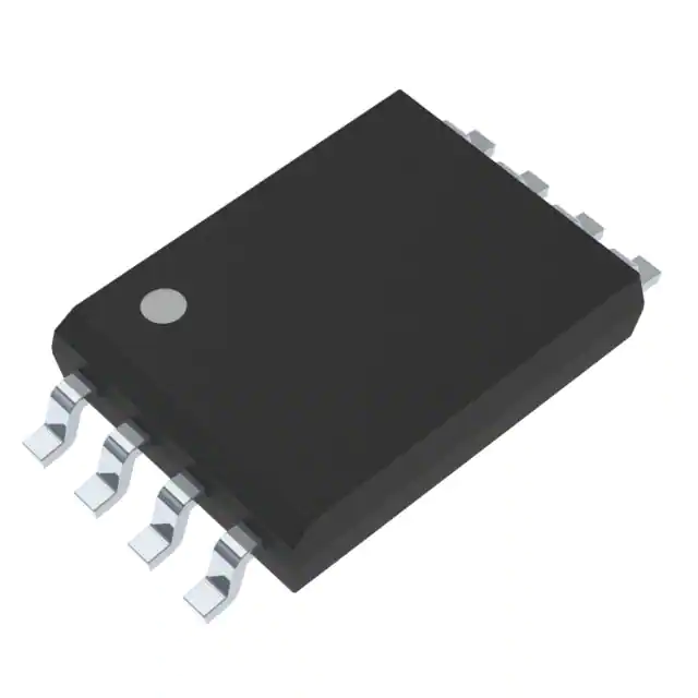
STMicroelectronics STGAP1BSTR
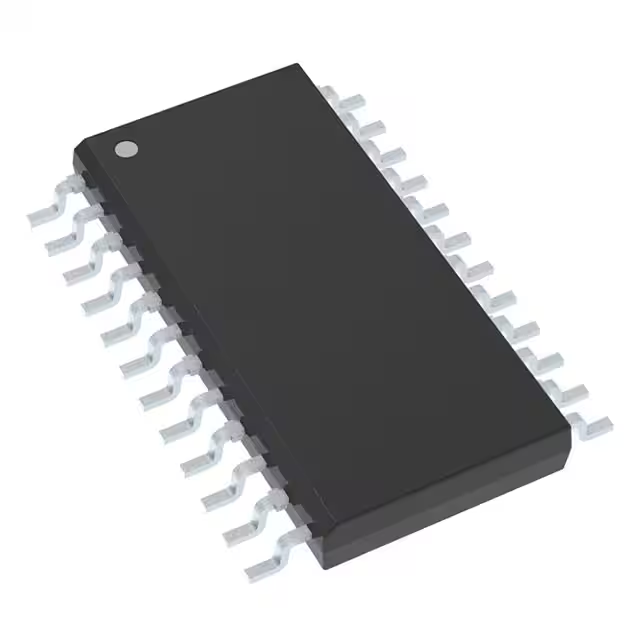
- Part No.:
- STGAP1BSTR
- Manufacturer:
- STMicroelectronics
- Category:
- Isolators - Gate Drivers
- Package:
- 24-SOIC (0.295", 7.50mm Width)
- Datasheet:
-
 STGAP1BSTR.pdf
- Description:
- SNGL ISOLATED GATE DRIVER 24SO
- Quantity:
- Payment:

- Shipping:

Inventory:981
Please send an inquiry. Send us your inquiry, and we will respond immediately.
Product details
Overview
STGAP1BSTR from STMicroelectronics is an AEC-Q100 qualified, galvanically isolated single-channel gate driver IC for N-channel MOSFETs and IGBTs, featuring 5 A sink/source peak output current, ±50 V/ns dV/dt immunity, 100 ns max input-output propagation delay, and integrated desaturation detection, Miller clamp, and VCE active clamping - deployed in EV traction inverters and industrial 1200 V three-phase drives.
For engineers reviewing the STGAP1BSTR datasheet, STGAP1BSTR pinout, STGAP1BSTR application, or STGAP1BSTR equivalent, key selection considerations include its programmable SPI-configurable protection thresholds (DESAT, SENSE, 2LTO), dual UVLO/OVLO on both VH/VL rails, negative gate drive capability via VL, and diagnostic status reporting through open-drain outputs and SPI register reads.
Technical Context
The STGAP1BSTR implements true galvanic isolation between low-voltage logic and high-voltage power stages, with 1500 VPEAK working voltage and 2500 VRMS isolation rating per UL 1577. Its architecture separates gate drive paths into independent GON (source) and GOFF (sink) outputs, enabling precise control of turn-on/turn-off timing and supporting negative gate bias down to –10 V via VL.
Protection logic is fully configurable via SPI: desaturation threshold (2.6–10.5 V), SENSE overcurrent trip (88–420 mV), 2-level turn-off trigger (6.65–15.23 V), and deadtime (250–1415 ns). All fault conditions - DESAT, VCE clamp timeout, overtemperature (125 °C warning / 155 °C shutdown), and regulator errors - generate latched flags accessible via STATUS registers and mapped to DIAG1/DIAG2 pins.
Key Specifications
| Parameter | Value and Actual Design Meaning |
|---|---|
| Isolation Voltage | 2500 VRMS (1 min), 1500 VPEAK working voltage - enables safe operation in 600/1200 V DC bus systems with reinforced insulation. |
| Output Drive Strength | 5 A sink/source at 25 °C - supports fast switching of high-Qg IGBTs/MOSFETs in >10 kW inverters without external buffers. |
| dV/dt Immunity | ±50 V/ns across full temperature range - prevents false triggering during high-speed commutation in noisy motor drive environments. |
| Propagation Delay | 100 ns max (ON/OFF) - ensures tight PWM timing control and <10 ns pulse width distortion for accurate duty cycle fidelity. |
| Protection Programmability | SPI-configurable DESAT (8 thresholds), SENSE (8 thresholds), 2LTO (16 thresholds), deadtime (3 settings) - eliminates hardware tuning and enables one-firmware support across multiple power stages. |
| Supply Rail Monitoring | Independent UVLO/OVLO on VDD (3.95/5.5 V), VH (9.4–14.7 V turn-on), VL (–7.35 to –2.8 V turn-on) - guarantees safe startup/shutdown sequencing in split-rail gate drive supplies. |
| Diagnostic Interface | Two open-drain diagnostic outputs (DIAG1/DIAG2) + full SPI status register map - enables real-time fault classification and system-level error logging without additional ADC or GPIO overhead. |
Pinout & Package
STGAP1BSTR is housed in a SO-24W (wide-body SOIC-24) package with 8 mm creepage/clearance, optimized for high-voltage isolation and thermal dissipation in automotive and industrial power modules.
| Pin/Terminal | Circuit Role | Design Meaning |
|---|---|---|
| 1, 12 GND | Low-side ground reference | Return path for logic supply (VDD/VREG) and digital I/Os; must be separated from high-side ground (GNDISO) to maintain isolation barrier. |
| 2 SDO | SPI serial data output | Push-pull or open-drain output delivering register readback data; requires external pull-up for open-drain mode. |
| 3 SDI | SPI serial data input | Accepts configuration commands and register writes; deglitched internally (50–580 ns filter selectable). |
| 4 CS | SPI chip select | Active-low enable for SPI transactions; rising edge triggers internal command latch and status flag clearing. |
| 5 CK | SPI clock | Supports up to 5 MHz clock rate; rise/fall times ≤25 ns required for reliable communication. |
| 6 VREG | LV regulator output | 3.3 V ±5% supply for logic core; shorted to VDD when external 3.3 V is used - disables internal LDO. |
| 7 VDD | LV power supply | 4.5–5.5 V input powering digital section; includes UVLO (3.95 V turn-on) and OVLO (5.5 V turn-on) with hysteresis. |
| 8 IN-/DIAG2 | Configurable logic input/output | Gate command input (IN-) or open-drain diagnostic output (DIAG2); direction controlled by SPI register. |
| 9 IN+ | Primary gate command input | CMOS-compatible input accepting 0.33×VDD to 0.66×VDD logic thresholds; internal 60 kΩ pull-down. |
| 10 DIAG1 | Dedicated diagnostic output | Open-drain output asserting low on fault events (DESAT, OVLO, REGERR); 300–800 kΩ internal pull-down. |
| 11 SD | Asynchronous shutdown | Active-low hard stop command overriding all logic states; forces GOFF ON, GON Hi-Z, CLAMP ON within 105 μs. |
| 13 GNDISO | High-side isolated ground | Reference for VH, VL, GON, GOFF, CLAMP, DESAT, SENSE, VCECLAMP - electrically isolated from GND by ≥8 mm creepage. |
| 14, 23 VL | Negative gate supply rail | Accepts –10 V to 0.3 V; enables negative gate bias for improved dv/dt immunity and Miller immunity in high-side switches. |
| 15 VREGISO | HV regulator output | 3.3 V output from HV-side LDO; decoupled with 4.7 µF capacitor to stabilize gate drive supply under transient load. |
| 16 SENSE | Overcurrent sense input | Analog input for shunt-based current monitoring; 8 programmable thresholds (88–420 mV) with 95 ns response time. |
| 17 VH | Positive gate supply rail | 4.5–36 V input powering high-side driver; includes UVLO (9.4–14.7 V turn-on) and OVLO (16.9–20 V turn-on). |
| 18 DESAT | Desaturation detection | Monitors IGBT VCE or MOSFET VDS; blanking time (160–340 ns) and threshold (2.6–10.5 V) are SPI-programmable. |
| 19 VCECLAMP | VCE active clamping | Connects to external clamping circuit; triggers when VCE exceeds VL + 1.6 V with 0.5 V hysteresis and 20 ns response. |
| 20 GON | Gate source output | Rail-to-rail output sourcing up to 5 A; high-level voltage = VH – 0.05 V @ 0.1 A, low-level = VL + 0.03 V @ 0.1 A. |
| 21 GOFF | Gate sink output | Rail-to-rail output sinking up to 5 A; supports 2-level turn-off with programmable voltage threshold and timing. |
| 22 CLAMP | Miller clamp output | Active clamp pulling gate to VL when Miller region detected; threshold = 2.0 V ±0.3 V vs. GNDISO. |
| 24 ASC | Asynchronous stop command | Secondary hard-stop input; 100–250 ns response time; overrides all logic and protection states immediately. |
Key Features
| Feature | Design Value |
|---|---|
| Galvanic Isolation Architecture | True isolation barrier with 8 mm creepage/clearance and 1500 VPEAK working voltage - eliminates need for external isolators in ASIL-B compliant EV inverter designs. |
| Programmable Dual-Rail Protection | Independent UVLO/OVLO on VDD, VH, and VL rails with user-selectable thresholds - ensures robust power sequencing in multi-supply gate driver topologies. |
| Configurable Fault Response | SPI-selectable 2-level turn-off (voltage + timing), DESAT blanking, and SENSE filtering - enables optimization of fault handling for specific IGBT/MOSFET switching characteristics. |
| Integrated Diagnostic Reporting | Two dedicated open-drain outputs (DIAG1/DIAG2) plus full SPI-accessible status registers - provides both immediate hardware fault signaling and detailed post-fault root-cause analysis. |
| Negative Gate Drive Support | VL pin accepts –10 V supply enabling negative gate bias - reduces Miller-induced shoot-through risk in high-dv/dt half-bridge configurations. |
Applications
| EV Traction Inverter | Solar String Inverter |
|---|---|
Use Scenario: Driving 1200 V SiC MOSFETs in a 3-phase 150 kW traction inverter for battery electric vehicles, operating at 10–20 kHz switching frequency with strict ASIL-B functional safety requirements. IC Role / Device Role / Timing Role: Isolated gate driver providing reinforced insulation, desaturation detection, and 2-level turn-off to protect against short-circuit faults during torque transients. Use Value: Enables compliance with ISO 26262 via latched fault flags, programmable DESAT thresholds matching SiC device VDS saturation, and diagnostic coverage >90% per FMEDA. | Use Scenario: Controlling 600 V IGBTs in a 10 kW solar string inverter with MPPT tracking, operating in outdoor environments with wide ambient temperature variation (–40 to +85 °C). IC Role / Device Role / Timing Role: High-reliability gate driver with ±50 V/ns dV/dt immunity and thermal shutdown (155 °C) to sustain operation under partial shading and grid fault conditions. Use Value: Eliminates external Miller clamp circuits and discrete overvoltage protection, reducing BOM count by 4 components while maintaining >10-year field reliability. |
| Industrial Motor Drive | EV DC Fast Charging Station |
Use Scenario: Powering 400 V AC induction motors in HVAC compressors and pumps using 600 V IGBTs in a 3-level NPC topology, requiring precise deadtime control and VCE clamping. IC Role / Device Role / Timing Role: Configurable deadtime generator (250–1415 ns) and VCE active clamping interface to suppress voltage spikes during soft-switching transitions. Use Value: Reduces EMI filter size by 30% through controlled switching edge rates and eliminates snubber losses via active clamping. | Use Scenario: Managing 1200 V Si IGBTs in a 150 kW liquid-cooled DC fast charger power stage, subject to frequent thermal cycling and grid voltage surges. IC Role / Device Role / Timing Role: AEC-Q100 qualified gate driver with dual-rail UVLO, overtemperature warning (125 °C), and asynchronous stop (ASC) for emergency shutdown during ground fault events. Use Value: Supports UL 1577 certification for charging infrastructure and enables predictive maintenance via SPI-read temperature and fault history logs. |
Equivalent & Alternatives
The following parts are listed as comparable options for similar isolated gate driver applications.
| Alternative Part | Technical Difference | Application Difference | Selection Advice |
|---|---|---|---|
| Si827x (Silicon Labs) | Non-isolated logic inputs; no SPI programming; fixed DESAT threshold (7 V); no VCE clamping or SENSE input. | Limited to simpler 600 V inverters without advanced fault management; lacks automotive qualification. | Choose for cost-sensitive industrial drives where programmability and AEC-Q100 are not required. |
| UCC5870-Q1 (TI) | Higher 10 A drive strength; integrated isolated DC/DC; no separate VL pin; fixed 2LTO; no ASC input. | Better suited for high-power SiC modules but lacks negative gate bias and asynchronous hard-stop capability. | Prefer for >200 kW traction inverters needing higher drive current, but verify absence of VL support matches your gate bias scheme. |
Compared with Si827x and UCC5870-Q1, STGAP1BSTR uniquely combines AEC-Q100 qualification, negative gate drive (VL), SPI-configurable protection, and asynchronous stop (ASC) - making it the only option supporting ASIL-B-compliant, field-upgradable fault response in compact 1200 V EV power stages.
Availability
STGAP1BSTR is available at Aetrix Electronics and suitable for EV traction inverters, solar string inverters, industrial motor drives, and EV DC fast charging stations requiring stable component supply, long-term lifecycle assurance, and automotive-grade reliability.
Supply support for STGAP1BSTR includes scheduled delivery planning, volume procurement assistance, BOM continuity management, traceable sourcing, and lifecycle availability coordination for OEM customers, industrial embedded developers, connected-device designers, and electronics production programs.
Manufacturer
STMicroelectronics is a global semiconductor leader headquartered in Geneva, Switzerland, designing and manufacturing microcontrollers, power ICs, sensors, and analog devices for automotive, industrial, and consumer markets.
The STGAP1BSTR belongs to ST's STGAP family of isolated gate drivers, engineered specifically for high-reliability, high-voltage power conversion systems requiring functional safety, programmable protection, and reinforced galvanic isolation.
FAQ
What is the maximum switching frequency supported by STGAP1BSTR?
The datasheet specifies a maximum recommended switching frequency of 150 kHz, limited by thermal constraints and propagation delay stability. At 100 kHz, typical power dissipation remains below 65 mW in the input section and within thermal limits of the SO-24W package (Rth(JA) = 65 °C/W). Higher frequencies require careful PCB layout and heatsinking to avoid junction temperature exceeding 150 °C.
How does the SPI interface handle fault flag clearing?
Fault flags (UVLOD, OVLOD, DESAT, REGERRR, etc.) are latched and remain asserted until explicitly cleared via SPI write to the corresponding STATUS register bit. The CS rising edge initiates the clear sequence, and flags are reset only after successful register write - ensuring no spurious clearing during noise events. DIAG1/DIAG2 outputs reflect latched state, not raw fault pulses.
Can STGAP1BSTR drive both IGBTs and SiC MOSFETs?
Yes - STGAP1BSTR supports both device types via programmable protection thresholds: DESAT threshold ranges from 2.6 V to 10.5 V (matching IGBT VCE(sat) and SiC VDS(sat)), and SENSE threshold spans 88–420 mV (compatible with low-value shunts used for high-frequency SiC current sensing). Its 5 A drive strength and 25 ns rise/fall times meet typical SiC gate requirements.
What is the role of the ASC (asynchronous stop command) pin?
The ASC pin provides a hardware-level emergency shutdown path independent of SPI or logic states. When asserted high, it forces GOFF ON, GON Hi-Z, and CLAMP ON within 100–250 ns - bypassing all internal logic, protection timers, and register settings. It is intended for critical safety functions like ground fault interruption in EV chargers or DC link overvoltage events.
STGAP1BSTR Specifications
- Product attributes
- Attribute value
- Manufacturer:
- STMicroelectronics
- Series:
- -
- Package/Case:
- 24-SOIC (0.295", 7.50mm Width)
- Packaging:
- Tape & Reel (TR)
- Product Status:
- Active
- Technology:
- -
- Number of Channels:
- -
- Voltage - Isolation:
- -
- Common Mode Transient Immunity (Min):
- -
- Propagation Delay tpLH / tpHL (Max):
- -
- Pulse Width Distortion (Max):
- -
- Rise / Fall Time (Typ):
- -
- Current - Output High, Low:
- -
- Current - Peak Output:
- -
- Voltage - Forward (Vf) (Typ):
- -
- Current - DC Forward (If) (Max):
- -
- Voltage - Output Supply:
- -
- Grade:
- -
- Qualification:
- -
- Operating Temperature:
- -
- Mounting Type:
- Surface Mount
- Supplier Device Package:
- 24-SO
- Approval Agency:
- -
STGAP1BSTR FAQ
1.How can I place an order for STGAP1BSTR through Aetrix?
Please submit a Request for Quotation (RFQ) for STGAP1BSTR on Aetrix. Our sales agent will provide a competitive quotation and guide you through the order confirmation once you accept the terms.
2.Are the price and stock information for STGAP1BSTR reliable?
The price and inventory of STGAP1BSTR are updated periodically and may fluctuate due to market conditions. Stock and pricing data are typically refreshed every 24 hours. Quotation validity for STGAP1BSTR is usually 5 days.
3.What payment methods are accepted for STGAP1BSTR?
We accept Wire Transfer, PayPal, Credit Card, Western Union, MoneyGram, and Escrow for STGAP1BSTR transactions.
Note: Certain payment methods may incur a processing fee.
4.How is shipping managed for STGAP1BSTR?
STGAP1BSTR orders can be shipped via leading logistics carriers, including DHL, UPS, FedEx, TNT, or Registered Mail.
Once your STGAP1BSTR order is processed, you will receive an email with the shipment details and tracking number.
Note: Tracking information may take up to 24 hours to appear. Express delivery typically takes 3–5 business days.
5.How can I obtain technical support or documentation for STGAP1BSTR?
For technical support, including STGAP1BSTR datasheets, pinout diagrams, or application guidance, please contact our engineering support team. They can provide detailed documentation and assistance for your STGAP1BSTR requirements.
6.How does Aetrix verify that STGAP1BSTR is sourced from the original manufacturer or authorized distributors?
All STGAP1BSTR products on Aetrix are procured from qualified distributors and authorized channels. Our dedicated quality assurance team conducts strict verification, including traceability checks and, if necessary, third-party testing. This ensures that STGAP1BSTR meets industry standards.
7.What is the process for return or replacement of STGAP1BSTR?
All STGAP1BSTR units undergo pre-shipment inspection (PSI). If there is an issue with STGAP1BSTR, returns or replacements are accepted under the following conditions:
1.Quantity discrepancies, incorrect items, or visible external defects (such as breakage or corrosion), acknowledged by Aetrix.
2.The issue is reported within 90 days of delivery.
3.The STGAP1BSTR part is unused and in its original packaging.
Return procedure for STGAP1BSTR:
1.Submit a request within 90 days.
2.Obtain a Return Material Authorization (RMA) from Aetrix.
STGAP1BSTR Tags
.JPG)
-
TLP152(TPL,E
Toshiba Semiconductor and Storage

-
HT0740LG-G
Microchip Technology
-
FOD8314TR2
onsemi
-
1EDI60N12AFXUMA1
Infineon Technologies
-
1EDB7275FXUMA1
Infineon Technologies
-
UCC5350MCDR
Texas Instruments

-
2EDB7259KXUMA1
Infineon Technologies

-
UCC5304DWVR
Texas Instruments
-
SI8261BBC-C-ISR
Skyworks Solutions Inc.
-
HT0440LG-G
Microchip Technology
-
HCPL-0302-500E
Broadcom Limited
-
STGAP2HSCMTR
STMicroelectronics
Tech Hub

A practical engineering and sourcing framework covering lifecycle verification, lifetime-buy calculations, replacement qualification, supplier checks and counterfeit-risk controls.

TTL and CMOS logic families differ in thresholds, loading, output drive, power and timing. This engineering guide compares 74HC and 74HCT, calculates noise margins and checks 3.3 V/5 V compatibility.

A practical engineering guide to 3.3V and 5V logic compatibility, input thresholds, resistor dividers, translator ICs, MOSFET level shifting, I2C pull-ups, timing limits and power-sequencing risks.

The 74HC595 uses push-pull logic outputs, while the TPIC6B595 uses 50 V open-drain DMOS sinks for higher-power loads. This guide compares timing, current limits, 3.3 V interfacing, load wiring, thermal…

The 74HC595 converts serial data into eight stable parallel outputs. This guide covers pin functions, shift and storage timing, OE and MR behavior, drive-current limits, cascading, voltage compatibilit…

A technical comparison of level-sensitive latches and edge-triggered flip-flops, covering timing windows, setup and hold limits, master–slave operation, time borrowing, race-through, HDL inference and…

A D latch stores one bit while Enable controls when data can pass. This reference covers gate-level operation, truth tables, transparency, setup and hold timing, LE versus OE, common ICs and practical …

An SR latch stores one bit through cross-coupled feedback. This engineering reference covers NOR and NAND implementations, truth tables, forbidden-state recovery, gated operation, switch debouncing, fa…

Latch circuits retain one bit through feedback. This technical reference covers SR and D latches, truth tables, transparency, timing limits, latch-versus-flip-flop behavior, applications and common log…

An engineering guide to LED driver operation, constant-current and constant-voltage outputs, linear and switching topologies, dimming, IC selection, calculations, replacement compatibility, and fault c…


