
 My Inquiry
 My Account


STMicroelectronics STLED524
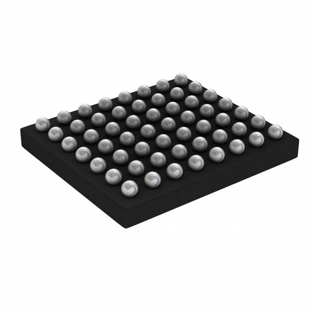
- Part No.:
- STLED524
- Manufacturer:
- STMicroelectronics
- Category:
- Display Drivers
- Package:
- 56-UFBGA, CSPBGA
- Datasheet:
-
 STLED524.pdf
- Description:
- IC DRVR DOT MATRIX 56CSP
- Quantity:
- Payment:

- Shipping:

Inventory:13,767
Please send an inquiry. Send us your inquiry, and we will respond immediately.
Product details
Overview
STLED524 from STMicroelectronics is an intelligent 5×24 dot-matrix LED display driver IC with integrated boost converter and LDO, designed for high-efficiency multiplexed LED control in space-constrained UIs. It delivers up to 20 mA per LED, supports 255-step PWM dimming and per-dot slope timing, and operates from 2.7 V to 5.5 V input. Used in appliance front panels requiring dynamic scrolling text and icon animation.
For engineers reviewing the STLED524 datasheet, STLED524 pinout, STLED524 application, or STLED524 equivalent, this page provides verified technical context, real-world design meaning of key specs, validated pin functions, application-specific implementation guidance, and confirmed alternative options for LED matrix driver selection.
Technical Context
The STLED524 implements a column-scanned 5-row × 24-column LED matrix using low-side current mirrors per LED, supplied by an internal 2.4 MHz boost converter whose output voltage is digitally adjustable (via register) to match LED forward voltage-reducing power loss in current regulation. An integrated 3.1 V/80 mA LDO powers auxiliary circuitry.
It features dual pattern memory (Pattern 1 & Pattern 2), four-directional hardware scroll with column/row locking, per-dot programmable blanking time, cycle time, and slope time, plus SPI interface for register configuration and status monitoring. Protection includes overvoltage, thermal shutdown, open/short ISET detection, and row transistor fault reporting.
Key Specifications
| Parameter | Value and Actual Design Meaning |
|---|---|
| LED Matrix Size | 5 rows × 24 columns - enables compact alphanumeric/icon displays without external row/column drivers |
| Max LED Current | 20 mA per dot - sufficient for bright visible indicators on white/green/red LEDs at typical VF |
| PWM Dimming Steps | 255 steps - allows fine-grained luminance control across wide ambient light conditions |
| Boost Converter Efficiency | 92% at 350 mA - minimizes thermal load in battery- or low-voltage-powered appliances |
| Slope Timing Resolution | Per-dot adjustable cycle & slope time - enables smooth animated transitions between display states |
| LDO Output | 3.1 V @ 80 mA - powers microcontroller I/O or logic circuitry without external regulator |
| SPI Interface | Full-duplex, register-addressed - simplifies host MCU firmware integration with minimal GPIO overhead |
Pinout & Package
CSP 56-bump package, 0.4 mm pitch, 3.4 mm × 3.0 mm footprint - optimized for ultra-thin appliance bezels and handheld device PCBs.
| Pin/Terminal | Circuit Role | Design Meaning |
|---|---|---|
| VIN | Input supply | 2.7–5.5 V main power rail feeding boost converter and LDO inputs |
| VOUT | Boost output | Adjustable DC-DC output (typically 12–24 V) driving LED column current mirrors |
| VDD | LDO output | Stable 3.1 V supply for host MCU or peripheral logic |
| ISET | Current reference | Analog pin setting max LED current via external resistor (RSET) |
| SCLK, SDI, SDO, CS | SPI interface | Standard 4-wire SPI for configuration, pattern loading, and status readback |
| SYNC | Frame synchronization | External trigger for synchronized multi-device display updates |
| INT | Interrupt output | Open-drain signal indicating faults (thermal, OV, short/open ISET, row error) |
| LEDx_y (120 pins) | LED cathode outputs | 5×24 low-side current-sink terminals - each drives one LED dot independently |
Key Features
| Feature | Design Value |
|---|---|
| Dual-pattern memory | Stores two independent 5×24 frame buffers - enables seamless static + scrolling content without host CPU intervention |
| 4-way hardware scroll | Configurable left/right/up/down movement with blank row/column insertion - reduces MCU processing load during animation |
| Per-dot slope timing | Independent cycle and slope duration registers for each of 120 LEDs - supports localized fade-in/fade-out effects |
| Integrated boost + LDO | Single-chip power solution eliminates need for external DC-DC and linear regulators - saves board area and BOM cost |
| Comprehensive fault protection | Real-time monitoring of thermal, overvoltage, ISET open/short, and row transistor failures - improves system reliability in unattended appliances |
Applications
| Appliance Control Panel | Handheld Device Display |
|---|---|
Use Scenario: Microwave oven or washing machine front panel showing timer countdown, program status, and error codes. IC Role / Device Role / Timing Role: Primary LED matrix controller managing 5×24 segmented icons and dynamic text via hardware scroll and dual-pattern buffering. Use Value: Reduces MCU firmware complexity by offloading animation timing and pattern switching; 20 mA drive ensures visibility under kitchen lighting. | Use Scenario: Portable medical monitor displaying vital sign trends and alarm indicators on compact LED grid. IC Role / Device Role / Timing Role: Low-power display driver with integrated 3.1 V LDO powering sensor interface MCU, while boost converter efficiently drives high-VF indicator LEDs. Use Value: 92% boost efficiency extends battery life; per-dot dimming enables adaptive brightness for clinical environments. |
| Industrial HMI Module | Consumer Electronics UI |
Use Scenario: Factory floor control box with status LEDs for machine readiness, fault alerts, and mode indication. IC Role / Device Role / Timing Role: Robust LED driver with thermal and overvoltage protection operating in variable-temperature industrial enclosures. Use Value: Integrated protections eliminate need for external supervision circuitry; CSP package withstands vibration and thermal cycling. | Use Scenario: Smart home thermostat showing temperature, schedule, and Wi-Fi status via animated icons. IC Role / Device Role / Timing Role: SPI-configured display engine enabling smooth icon transitions and scrolling weather forecasts without frame buffer RAM on host MCU. Use Value: Hardware scroll and slope modes reduce host CPU load and power consumption during idle display updates. |
Equivalent & Alternatives
The following parts are listed as comparable options for similar LED matrix driver applications.
| Alternative Part | Technical Difference | Application Difference | Selection Advice |
|---|---|---|---|
| TLC5947 | 24-channel constant-current sink with grayscale PWM (4096 steps); no integrated boost or LDO; requires external 5 V supply | Best for low-density, high-resolution grayscale LED arrays where external power is available and per-dot intensity precision >255 steps is required | Select when higher PWM resolution is critical and board space allows separate boost/LDO; not suitable for direct VIN-to-LED high-VF operation |
| IS31FL3731 | 16×10 matrix driver with auto-breathing, no boost converter; operates from 2.7–5.5 V; I²C interface only | Targeted at smaller displays (<160 dots) with simpler animation needs and I²C-only host interfaces | Choose for cost-sensitive, lower-pin-count designs where 5×24 matrix size and SPI interface are not mandatory |
Compared with TLC5947 and IS31FL3731, the STLED524 uniquely integrates boost conversion and LDO in a 5×24 configuration with hardware scroll-making it optimal for compact, self-powered appliance UIs needing robust, low-software-overhead LED control.
Availability
STLED524 is available at Aetrix Electronics and suitable for appliance user interfaces, handheld unit displays, and industrial HMI modules requiring stable component supply, long-lifecycle support, and consistent parametric performance across production batches.
Supply support for STLED524 includes scheduled delivery planning, volume procurement assistance, BOM continuity management, traceable sourcing, and lifecycle availability coordination for OEM customers, industrial embedded developers, connected-device designers, and electronics production programs.
Manufacturer
STMicroelectronics is a global semiconductor leader headquartered in Geneva, specializing in power management, microcontrollers, sensors, and analog ICs for industrial, automotive, and consumer markets.
The STLED524 belongs to ST's Intelligent LED Driver product line, engineered specifically for energy-efficient, feature-rich display control in space- and power-constrained embedded UIs-emphasizing integration, reliability, and ease of system-level implementation.
FAQ
What is the maximum total current the STLED524 can deliver to the LED matrix?
The STLED524 supports up to 20 mA per LED dot across its 120 outputs. With all LEDs lit simultaneously, peak current draw from the boost converter is approximately 350 mA - matching the rated output capability and 92% efficiency point specified in the datasheet. Total average current depends on multiplexing duty cycle and active dot count.
How does the automatic slope function improve display visual quality?
The slope function applies programmable, per-dot duty-cycle ramping (fade-in/fade-out) during state transitions - eliminating harsh LED on/off artifacts. By adjusting cycle time and slope duration independently for each dot, it enables smooth animations like scrolling text or breathing icons without MCU-level timing loops or frame buffer manipulation.
Can the STLED524 drive high-forward-voltage LEDs such as blue or white?
Yes - the integrated boost converter's output voltage is digitally adjustable (via BOOST control register) from ~12 V to ~24 V, allowing optimization for blue/white LEDs with VF up to 3.6 V per segment. This adaptability minimizes power dissipation in the current mirrors and maintains high overall efficiency even with demanding LED stacks.
Is the STLED524 pin-compatible with earlier ST LED drivers like STLED316?
No - the STLED524 uses a 56-bump CSP package with unique pin mapping and significantly enhanced functionality (dual-pattern memory, hardware scroll, per-dot slope, integrated LDO). It is not a drop-in replacement for STLED316 or other legacy drivers; PCB layout and firmware initialization must be redesigned to leverage its advanced features.
STLED524 Specifications
- Product attributes
- Attribute value
- Manufacturer:
- STMicroelectronics
- Series:
- -
- Package/Case:
- 56-UFBGA, CSPBGA
- Packaging:
- Tape & Reel (TR)
- Product Status:
- Active
- Display Type:
- LED
- Configuration:
- Dot Matrix
- Interface:
- SPI
- Digits or Characters:
- -
- Current - Supply:
- -
- Voltage - Supply:
- 2.7V ~ 5.5V
- Operating Temperature:
- -30°C ~ 85°C
- Grade:
- -
- Qualification:
- -
- Mounting Type:
- Surface Mount
- Supplier Device Package:
- 56-CSP (3.4x3.0)
STLED524 FAQ
1.How can I place an order for STLED524 through Aetrix?
Please submit a Request for Quotation (RFQ) for STLED524 on Aetrix. Our sales agent will provide a competitive quotation and guide you through the order confirmation once you accept the terms.
2.Are the price and stock information for STLED524 reliable?
The price and inventory of STLED524 are updated periodically and may fluctuate due to market conditions. Stock and pricing data are typically refreshed every 24 hours. Quotation validity for STLED524 is usually 5 days.
3.What payment methods are accepted for STLED524?
We accept Wire Transfer, PayPal, Credit Card, Western Union, MoneyGram, and Escrow for STLED524 transactions.
Note: Certain payment methods may incur a processing fee.
4.How is shipping managed for STLED524?
STLED524 orders can be shipped via leading logistics carriers, including DHL, UPS, FedEx, TNT, or Registered Mail.
Once your STLED524 order is processed, you will receive an email with the shipment details and tracking number.
Note: Tracking information may take up to 24 hours to appear. Express delivery typically takes 3–5 business days.
5.How can I obtain technical support or documentation for STLED524?
For technical support, including STLED524 datasheets, pinout diagrams, or application guidance, please contact our engineering support team. They can provide detailed documentation and assistance for your STLED524 requirements.
6.How does Aetrix verify that STLED524 is sourced from the original manufacturer or authorized distributors?
All STLED524 products on Aetrix are procured from qualified distributors and authorized channels. Our dedicated quality assurance team conducts strict verification, including traceability checks and, if necessary, third-party testing. This ensures that STLED524 meets industry standards.
7.What is the process for return or replacement of STLED524?
All STLED524 units undergo pre-shipment inspection (PSI). If there is an issue with STLED524, returns or replacements are accepted under the following conditions:
1.Quantity discrepancies, incorrect items, or visible external defects (such as breakage or corrosion), acknowledged by Aetrix.
2.The issue is reported within 90 days of delivery.
3.The STLED524 part is unused and in its original packaging.
Return procedure for STLED524:
1.Submit a request within 90 days.
2.Obtain a Return Material Authorization (RMA) from Aetrix.
STLED524 Tags

-
PCA8561AHN/AY
NXP Semiconductors

-
SN74LS47N
Texas Instruments

-
PCF85176T/1Y
NXP Semiconductors
-
PCF85176H/1,518
NXP Semiconductors

-
BU9796AMUV-E2
Rohm Semiconductor
-
PCA85176H/Q900/1,5
NXP Semiconductors
-
PCF8537AH/1,518
NXP Semiconductors

-
LM3914VX/NOPB
Texas Instruments

-
PCF85134HL/1,118
NXP Semiconductors

-
AS1115-BSST
ams-OSRAM USA INC.
-
PCA8534AH/Q900/1,5
NXP Semiconductors
-
LM3914V/NOPB
Texas Instruments
Tech Hub

A practical engineering guide to 3.3V and 5V logic compatibility, input thresholds, resistor dividers, translator ICs, MOSFET level shifting, I2C pull-ups, timing limits and power-sequencing risks.

The 74HC595 uses push-pull logic outputs, while the TPIC6B595 uses 50 V open-drain DMOS sinks for higher-power loads. This guide compares timing, current limits, 3.3 V interfacing, load wiring, thermal…

The 74HC595 converts serial data into eight stable parallel outputs. This guide covers pin functions, shift and storage timing, OE and MR behavior, drive-current limits, cascading, voltage compatibilit…

A technical comparison of level-sensitive latches and edge-triggered flip-flops, covering timing windows, setup and hold limits, master–slave operation, time borrowing, race-through, HDL inference and…

A D latch stores one bit while Enable controls when data can pass. This reference covers gate-level operation, truth tables, transparency, setup and hold timing, LE versus OE, common ICs and practical …

An SR latch stores one bit through cross-coupled feedback. This engineering reference covers NOR and NAND implementations, truth tables, forbidden-state recovery, gated operation, switch debouncing, fa…

Latch circuits retain one bit through feedback. This technical reference covers SR and D latches, truth tables, transparency, timing limits, latch-versus-flip-flop behavior, applications and common log…

An engineering guide to LED driver operation, constant-current and constant-voltage outputs, linear and switching topologies, dimming, IC selection, calculations, replacement compatibility, and fault c…

Operational amplifier guide covering op amp basics, feedback, ideal vs real op amps, common configurations, buffer circuits, offset, bias current, gain-bandwidth, slew rate, rail-to-rail limits and sel…

Jumper cables guide covering safe connection order, red and black clamp placement, final ground connection, cable gauge, length, clamp quality, copper vs CCA cables, jump starter comparison and battery…


