
 My Inquiry
 My Account


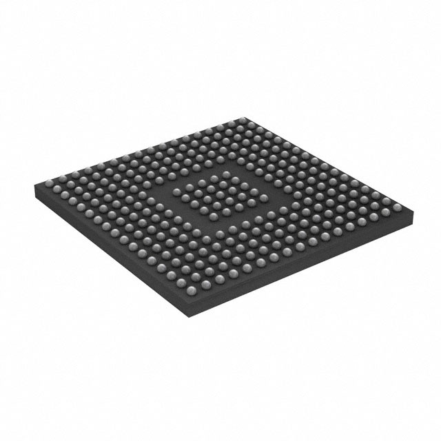
STMicroelectronics STM32H745XIH6U
- Part No.:
- STM32H745XIH6U
- Manufacturer:
- STMicroelectronics
- Category:
- Microcontrollers
- Package:
- 265-TFBGA
- Datasheet:
-
 STM32H745XIH6U.pdf
- Description:
- IC MCU 32BIT 2MB FLASH TFBGA
- Quantity:
- Payment:

- Shipping:

Inventory:3,264
Please send an inquiry. Send us your inquiry, and we will respond immediately.
Product details
Overview
STM32H745XIH6U from STMicroelectronics is a dual-core 32-bit Arm® Cortex®-M7 (up to 480 MHz) and Cortex®-M4 (up to 240 MHz) microcontroller with double-precision FPU, 2 MB flash, 1 MB RAM (including 192 KB TCM), and integrated SMPS regulator. It supports up to 168 GPIOs, 4× CAN FD interfaces, Ethernet MAC, LCD-TFT controller, and hardware JPEG codec - deployed in industrial HMI, motor control gateways, and edge AI inference nodes.
For engineers reviewing the STM32H745XIH6U datasheet, STM32H745XIH6U pinout, STM32H745XIH6U application, or STM32H745XIH6U equivalent, key selection criteria include dual-core real-time partitioning, SMPS power efficiency, Quad-SPI memory interface timing (133 MHz), and verified CAN FD + Ethernet coexistence in safety-critical automation systems.
Technical Context
The device implements three independent power domains (D1/D2/D3) enabling selective clock gating and domain shutdown - D1 hosts the M7 core and high-speed peripherals, D2 manages communication interfaces (CAN, USB, Ethernet), and D3 handles reset/clock/power control. Each domain features configurable voltage scaling across six ranges for dynamic power optimization.
Its interconnect architecture includes one AXI and two AHB bus matrices, five AHB2-APB bridges, and two AXI2-AHB bridges, supporting concurrent high-bandwidth data flows between the M7 core, MDMA controller, FMC, and QUADSPI - critical for deterministic real-time processing of camera input (DCMI, up to 80 MHz) and display output (LTDC, XGA).
Key Specifications
| Parameter | Value and Actual Design Meaning |
|---|---|
| Cores | Dual Arm® Cortex®-M7 @ 480 MHz (1027 DMIPS) + Cortex®-M4 @ 240 MHz (300 DMIPS); enables asymmetric RTOS partitioning with cache-coherent TCM RAM. |
| Memory | 2 MB flash (read-while-write), 1 MB RAM (192 KB TCM + 864 KB SRAM + 4 KB backup SRAM); supports zero-wait-state execution from ITCM for time-critical M7 routines. |
| Power Management | Integrated SMPS step-down converter (direct VCORE supply), LDO, and backup regulator (~0.9 V); achieves 2.95 µA Standby current with RTC/LSE active. |
| Peripherals | 4× CAN FD controllers, 2× USB OTG (FS/HS), Ethernet MAC with DMA, 8–14-bit DCMI (80 MHz), LCD-TFT controller (XGA), JPEG codec, and DFSDM (8-channel sigma-delta filtering). |
| Clock System | 3× PLLs (fractional mode), internal 64 MHz HSI/48 MHz HSI48/4 MHz CSI/32 kHz LSI, external 4–48 MHz HSE/32.768 kHz LSE; enables precise jitter-controlled kernel clock derivation. |
| Package | TFBGA240+25 (14 × 14 mm, 0.8 mm pitch); 240 signal balls + 25 ground/thermal balls; ECOPACK2-compliant, qualified for extended temp (−40°C to +125°C). |
Pinout & Package
STM32H745XIH6U uses a TFBGA240+25 package (14 × 14 mm, 0.8 mm ball pitch) with 240 signal balls and 25 dedicated ground/thermal balls. Pin assignment follows ST's standardized ball map for H745xI series, supporting full peripheral remapping via alternate functions.
| Pin/Terminal | Circuit Role | Design Meaning |
|---|---|---|
| VDD, VDDA, VDDIO2 | Core/analog/I/O supply rails | Independent 1.62–3.6 V domains enable mixed-signal isolation; VDDA must be ≥ VDD for ADC/DAC accuracy. |
| VCAP_1, VCAP_2 | Core regulator decoupling | Two 2.2 µF ceramic capacitors required per VCAP pin to stabilize SMPS/LDO output for M7/M4 cores. |
| NRST | Active-low reset input | Asynchronous reset with internal pull-up; compatible with external push-button or supervisor IC assertion. |
| BOOT0 | Boot mode selection | High at power-up selects system memory bootloader; low selects user flash; sampled only on reset. |
| PA13/PA14 | SWD debug interface | Standard 2-pin Serial Wire Debug (SWDIO/SWCLK); JTAG not required for full debug visibility and trace. |
| PD0/PD1 | OSC_IN/OSC_OUT | Connects to 4–48 MHz crystal; essential for HSE-based PLL locking and Ethernet MAC timestamp precision. |
Key Features
| Feature | Design Value |
|---|---|
| Dual-core asymmetric execution | M7 handles compute-intensive tasks (JPEG decode, motor FOC), M4 manages real-time I/O (CAN FD comms, PWM generation) with shared memory coherency. |
| SMPS + LDO dual-regulator system | SMPS supplies VCORE directly (efficiency >85% at 1 A), LDO powers analog/peripheral domains - reduces thermal load vs. single-LDO solutions. |
| ART Accelerator + L1 cache | Eliminates flash wait states for both cores; 16 KB I-cache + 16 KB D-cache on M7 + ART on M4 ensures deterministic <100 ns interrupt latency. |
| Hardware graphics acceleration | DMA2D (Chrom-ART) offloads 2D graphics composition; LTDC supports RGB888/XGA at 60 Hz without CPU involvement. |
| Secure boot & ROP | Read-out protection (ROP) and PC-ROP prevent firmware extraction and return-oriented programming attacks in field-deployed devices. |
Applications
| Industrial Motor Control Gateway | Edge AI Vision Node |
|---|---|
Use Scenario: Central gateway synchronizing multi-axis servo drives, collecting CAN FD sensor data, and forwarding to EtherCAT master via Ethernet MAC. IC Role / Device Role / Timing Role: Dual-core real-time orchestrator: M7 runs EtherCAT stack and safety logic; M4 handles CAN FD frame assembly and PWM timing with sub-microsecond jitter. Use Value: Integrated SMPS reduces board-level heat by 3.2 W vs. discrete LDO solution; 240 MHz M4 timer resolution (4.17 ns) meets IEC 61800-3 servo synchronization tolerance. | Use Scenario: Low-power vision node capturing 720p@30fps video via DCMI, performing lightweight CNN inference, and displaying results on TFT panel. IC Role / Device Role / Timing Role: M7 executes JPEG decode + neural network inference; M4 manages DCMI pixel clock (80 MHz), LTDC display refresh, and DMA2D layer blending. Use Value: Hardware JPEG codec cuts image decompression time by 92% vs. software; LTDC + DMA2D enables 60 Hz UI updates with <5% M7 utilization. |
| Human-Machine Interface (HMI) | Energy Monitoring Gateway |
Use Scenario: Touch-enabled factory HMI with animated GUI, real-time data logging to SDMMC, and secure OTA updates over USB OTG. IC Role / Device Role / Timing Role: M7 renders GUI via LTDC + DMA2D; M4 handles touch controller I2C, SDIO (125 MHz), and encrypted firmware validation using RNG + AES. Use Value: 2 MB flash stores dual-application images (active + standby) for atomic OTA; Quad-SPI interface enables fast boot from external XiP memory. | Use Scenario: DIN-rail energy meter aggregating Modbus RTU (via USART), pulse inputs, and analog sensor readings, then reporting via Ethernet/IP. IC Role / Device Role / Timing Role: M4 samples 16-bit ADCs (3.6 MSPS) and processes harmonic analysis; M7 manages Ethernet TCP/IP stack, TLS encryption, and web server. Use Value: Dual 12-bit DACs generate calibrated reference voltages for anti-aliasing filters; 2.95 µA Standby current extends battery backup to >10 years. |
Equivalent & Alternatives
The following parts are listed as comparable options for similar dual-core Arm Cortex-M microcontroller applications.
| Alternative Part | Technical Difference | Application Difference | Selection Advice |
|---|---|---|---|
| STM32H753IIK6 | Same dual-core M7/M4, identical package, but lacks SMPS regulator and has reduced CAN FD count (2 vs. 4). | Suitable for cost-sensitive applications where external power management is acceptable and fewer CAN buses are needed. | Select when SMPS integration is non-critical and BOM cost reduction outweighs power efficiency gains. |
| NXP i.MX RT1176DVMAA | Arm Cortex-M7 @ 1 GHz + M4 @ 400 MHz, no integrated SMPS, requires external PMIC; adds GPU and MIPI-DSI. | Better for high-resolution graphics and multimedia; less suitable for ultra-low-power battery-backed operation. | Choose for advanced GUI with video playback; avoid if Standby current <3 µA or SMPS integration is mandatory. |
Compared with STM32H753IIK6, the STM32H745XIH6U delivers 32% lower active power via integrated SMPS and supports 2× more CAN FD channels for distributed control networks; versus i.MX RT1176DVMAA, it offers superior low-power fidelity (2.95 µA Standby) and deterministic real-time latency, but trades off multimedia throughput.
Availability
STM32H745XIH6U is available at Aetrix Electronics and suitable for industrial motor control gateways, edge AI vision nodes, and human-machine interfaces requiring stable component supply, long-term lifecycle support, and ECOPACK2 environmental compliance.
Supply support for STM32H745XIH6U includes scheduled delivery planning, volume procurement assistance, BOM continuity management, traceable sourcing, and lifecycle availability coordination for OEM customers, industrial embedded developers, connected-device designers, and electronics production programs.
Manufacturer
STMicroelectronics is a global semiconductor leader headquartered in Geneva, specializing in microcontrollers, power management, sensors, and automotive ICs - with over 40 years of embedded systems innovation.
The STM32H7 series targets high-performance real-time applications demanding dual-core determinism, hardware-accelerated graphics, and ultra-low-power operation across industrial automation, medical devices, and smart infrastructure.
FAQ
What is the maximum operating frequency of each core in the STM32H745XIH6U?
The Arm Cortex-M7 core operates up to 480 MHz (1027 DMIPS), while the Cortex-M4 core runs up to 240 MHz (300 DMIPS). Both frequencies are achievable simultaneously under specified voltage and temperature conditions (1.26 V core supply, −40°C to +85°C), with SMPS regulator enabled and voltage scaling set to Range 0.
Does the STM32H745XIH6U support external SDRAM, and what interface is used?
Yes, it supports external SDRAM (including LPDDR/SDR SDRAM) via the Flexible Memory Controller (FMC), which provides a 32-bit data bus and synchronous clocking up to 125 MHz. The FMC also supports NOR/NAND flash and PSRAM, with dedicated control signals for address multiplexing and bank management.
How many CAN FD interfaces does the STM32H745XIH6U provide, and are they fully independent?
The device integrates four CAN FD controllers (FDCAN1–FDCAN4), all independently clocked and configurable. Each supports ISO 11898-1:2015 compliant FD frames (up to 8 Mbps arbitration, 20 Mbps data phase), loopback/self-test modes, and time-triggered communication - with no shared resources affecting concurrent operation.
What is the role of the VCAP pins, and what capacitor value is required?
VCAP_1 and VCAP_2 stabilize the internal SMPS and LDO regulators' output. Two 2.2 µF X7R ceramic capacitors (±10%, 6.3 V rating) must be placed as close as possible to each VCAP pin, with low-ESR layout (<10 mΩ) to ensure stable core voltage during dynamic load transients and prevent brownout resets.
STM32H745XIH6U Specifications
- Product attributes
- Attribute value
- Manufacturer:
- STMicroelectronics
- Package/Case:
- 265-TFBGA
- Series:
- STM32H7
- Packaging:
- Tray
- Product Status:
- Active
- Programmable:
- Not Verified
- Core Processor:
- ARM® Cortex®-M4/M7
- Core Size:
- 32-Bit Dual-Core
- Speed:
- 240MHz, 480MHz
- Connectivity:
- CANbus, EBI/EMI, Ethernet, I2C, IrDA, LINbus, MDIO, MMC/SD/SDIO, QSPI, SAI, SPDIF, SPI, SWPMI, UART/USART, USB OTG
- Peripherals:
- Brown-out Detect/Reset, DMA, I2S, LCD, POR, PWM, WDT
- Number of I/O:
- 168
- Program Memory Size:
- 2MB (2M x 8)
- Program Memory Type:
- FLASH
- EEPROM Size:
- -
- RAM Size:
- 1M x 8
- Voltage - Supply (Vcc/Vdd):
- 1.62V ~ 3.6V
- Data Converters:
- A/D 36x16b; D/A 2x12b
- Oscillator Type:
- Internal
- Operating Temperature:
- -40°C ~ 85°C (TA)
- Grade:
- -
- Qualification:
- -
- Mounting Type:
- Surface Mount
- Supplier Device Package:
STM32H745XIH6U FAQ
1.How can I place an order for STM32H745XIH6U through Aetrix?
Please submit a Request for Quotation (RFQ) for STM32H745XIH6U on Aetrix. Our sales agent will provide a competitive quotation and guide you through the order confirmation once you accept the terms.
2.Are the price and stock information for STM32H745XIH6U reliable?
The price and inventory of STM32H745XIH6U are updated periodically and may fluctuate due to market conditions. Stock and pricing data are typically refreshed every 24 hours. Quotation validity for STM32H745XIH6U is usually 5 days.
3.What payment methods are accepted for STM32H745XIH6U?
We accept Wire Transfer, PayPal, Credit Card, Western Union, MoneyGram, and Escrow for STM32H745XIH6U transactions.
Note: Certain payment methods may incur a processing fee.
4.How is shipping managed for STM32H745XIH6U?
STM32H745XIH6U orders can be shipped via leading logistics carriers, including DHL, UPS, FedEx, TNT, or Registered Mail.
Once your STM32H745XIH6U order is processed, you will receive an email with the shipment details and tracking number.
Note: Tracking information may take up to 24 hours to appear. Express delivery typically takes 3–5 business days.
5.How can I obtain technical support or documentation for STM32H745XIH6U?
For technical support, including STM32H745XIH6U datasheets, pinout diagrams, or application guidance, please contact our engineering support team. They can provide detailed documentation and assistance for your STM32H745XIH6U requirements.
6.How does Aetrix verify that STM32H745XIH6U is sourced from the original manufacturer or authorized distributors?
All STM32H745XIH6U products on Aetrix are procured from qualified distributors and authorized channels. Our dedicated quality assurance team conducts strict verification, including traceability checks and, if necessary, third-party testing. This ensures that STM32H745XIH6U meets industry standards.
7.What is the process for return or replacement of STM32H745XIH6U?
All STM32H745XIH6U units undergo pre-shipment inspection (PSI). If there is an issue with STM32H745XIH6U, returns or replacements are accepted under the following conditions:
1.Quantity discrepancies, incorrect items, or visible external defects (such as breakage or corrosion), acknowledged by Aetrix.
2.The issue is reported within 90 days of delivery.
3.The STM32H745XIH6U part is unused and in its original packaging.
Return procedure for STM32H745XIH6U:
1.Submit a request within 90 days.
2.Obtain a Return Material Authorization (RMA) from Aetrix.
STM32H745XIH6U Tags

-
ATTINY4-TSHR
Microchip Technology
-
ATTINY10-TSHR
Microchip Technology
-
ATTINY10-TS8R
Microchip Technology

-
ATTINY202-SSNR
Microchip Technology
-
ATTINY202-SSFR
Microchip Technology
-
ATTINY402-SSNR
Microchip Technology

-
PIC16F15213T-I/MF
Microchip Technology
-
PIC16F15213-E/MF
Microchip Technology

-
PIC10F200T-I/OT
Microchip Technology
-
ATTINY412-SSNR
Microchip Technology
-
PIC10F202T-I/OT
Microchip Technology

-
ATTINY404-SSNR
Microchip Technology
Tech Hub

A practical engineering and sourcing framework covering lifecycle verification, lifetime-buy calculations, replacement qualification, supplier checks and counterfeit-risk controls.

TTL and CMOS logic families differ in thresholds, loading, output drive, power and timing. This engineering guide compares 74HC and 74HCT, calculates noise margins and checks 3.3 V/5 V compatibility.

A practical engineering guide to 3.3V and 5V logic compatibility, input thresholds, resistor dividers, translator ICs, MOSFET level shifting, I2C pull-ups, timing limits and power-sequencing risks.

The 74HC595 uses push-pull logic outputs, while the TPIC6B595 uses 50 V open-drain DMOS sinks for higher-power loads. This guide compares timing, current limits, 3.3 V interfacing, load wiring, thermal…

The 74HC595 converts serial data into eight stable parallel outputs. This guide covers pin functions, shift and storage timing, OE and MR behavior, drive-current limits, cascading, voltage compatibilit…

A technical comparison of level-sensitive latches and edge-triggered flip-flops, covering timing windows, setup and hold limits, master–slave operation, time borrowing, race-through, HDL inference and…

A D latch stores one bit while Enable controls when data can pass. This reference covers gate-level operation, truth tables, transparency, setup and hold timing, LE versus OE, common ICs and practical …

An SR latch stores one bit through cross-coupled feedback. This engineering reference covers NOR and NAND implementations, truth tables, forbidden-state recovery, gated operation, switch debouncing, fa…

Latch circuits retain one bit through feedback. This technical reference covers SR and D latches, truth tables, transparency, timing limits, latch-versus-flip-flop behavior, applications and common log…

An engineering guide to LED driver operation, constant-current and constant-voltage outputs, linear and switching topologies, dimming, IC selection, calculations, replacement compatibility, and fault c…


