
 My Inquiry
 My Account


STMicroelectronics STM32L011F4U6TR
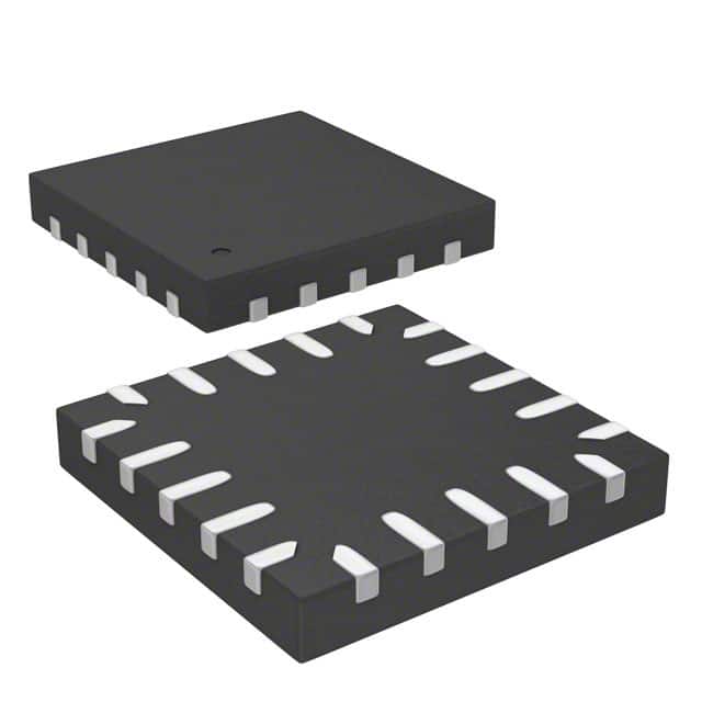
- Part No.:
- STM32L011F4U6TR
- Manufacturer:
- STMicroelectronics
- Category:
- Microcontrollers
- Package:
- 20-UFQFN
- Datasheet:
-
 STM32L011F4U6TR.pdf
- Description:
- IC MCU 32BIT 16KB FLASH 20UFQFPN
- Quantity:
- Payment:

- Shipping:

Inventory:18,637
Please send an inquiry. Send us your inquiry, and we will respond immediately.
Product details
Overview
STM32L011F4U6TR from STMicroelectronics is an ultra-low-power 32-bit Arm® Cortex®-M0+ microcontroller in UFQFPN20 (3×3 mm) package, featuring 16 KB Flash, 2 KB SRAM, 512 B EEPROM with ECC, 12-bit ADC (1.14 Msps), and dual ultra-low-power comparators. It operates from 1.65–3.6 V across –40 to +125 °C and delivers 76 µA/MHz in Run mode - ideal for battery-powered sensor nodes and smart metering endpoints.
For engineers reviewing the STM32L011F4U6TR datasheet, STM32L011F4U6TR pinout, STM32L011F4U6TR application, or STM32L011F4U6TR equivalent, key selection criteria include standby current (0.23 µA), RTC-enabled Stop mode (0.54 µA), 5 µs Flash wakeup, 23 I/Os (20 of which are 5V-tolerant), and integrated ECC for Flash and EEPROM - all critical for long-life embedded control in constrained environments.
Technical Context
The STM32L011F4U6TR implements a single-core Arm Cortex-M0+ running at up to 32 MHz with 0.95 DMIPS/MHz performance, supported by multiple clock sources: 16 MHz factory-trimmed HSI (±1%), 32 kHz LSE for RTC calibration, and multispeed MSI (65 kHz–4.2 MHz). Its power architecture includes dynamic voltage scaling and five low-power modes - Standby, Stop, Low-power Run, Sleep, and Run - each with defined current profiles and wakeup latency.
Peripherals are routed via an interconnect matrix supporting concurrent DMA transfers across ADC, USART, SPI, I2C, and timers. The device integrates a 96-bit unique ID, CRC calculation unit, serial wire debug (SW-DP), and pre-programmed bootloader supporting USART and SPI - enabling secure, field-upgradable firmware deployment without external programming hardware.
Key Specifications
| Parameter | Value and Actual Design Meaning |
|---|---|
| Core | Arm Cortex-M0+, 32-bit, up to 32 MHz - enables deterministic real-time control with minimal code footprint and energy per instruction. |
| Memory | 16 KB Flash (ECC-protected), 2 KB SRAM, 512 B EEPROM (ECC-protected) - ensures data integrity in harsh environments and supports parameter retention across power cycles. |
| Power Consumption | 0.23 µA Standby (2 wakeup pins), 0.54 µA Stop + RTC + 2 KB RAM retention - extends coin-cell battery life to >10 years in periodic-sensing applications. |
| ADC | 12-bit, 1.14 Msps, 10-channel, operational down to 1.65 V - allows high-resolution analog sensing without external supply boosting. |
| Timers | 7 timers: 2x 16-bit general-purpose (up to 4/2 channels), 1x ultra-low-power LPTIM, SysTick, RTC, 2x watchdogs - supports precise timing, pulse generation, and safety-critical timeout monitoring. |
| I/O Voltage Tolerance | 23 I/Os total; 20 pins 5V-tolerant - simplifies interface with legacy 5V peripherals without level-shifting circuitry. |
| Debug Interface | Serial Wire Debug (SW-DP) - enables non-intrusive real-time debugging and flash programming using standard ST-LINK tools. |
Pinout & Package
STM32L011F4U6TR is housed in a 20-pin Ultra Thin Fine Pitch Quad Flat No-lead (UFQFPN20) package, 3×3 mm body, 0.5 mm pitch, with exposed thermal pad. This compact, leadless package supports high-density PCB layouts and offers excellent thermal performance for space-constrained IoT endpoints.
| Pin/Terminal | Circuit Role | Design Meaning |
|---|---|---|
| VDD | Power supply (core & I/O) | 1.65–3.6 V main supply; powers CPU, memories, and digital peripherals - requires local decoupling near pin. |
| VSS | Ground reference | Digital ground return path; must be connected to low-impedance PCB plane for noise immunity and stable ADC operation. |
| NRST | Active-low reset input | Asynchronous reset trigger; internal pull-up enabled; accepts 1.65–3.6 V logic levels - used for system recovery and safe startup. |
| PA0 | General-purpose I/O / ADC1_IN0 / COMP1_INP | Configurable as GPIO, analog input for 12-bit ADC channel 0, or non-inverting input for comparator 1 - enables direct sensor interface. |
| PA1 | General-purpose I/O / ADC1_IN1 / COMP2_INP | Multi-function pin supporting ADC channel 1 or comparator 2 non-inverting input - supports differential sensing with PA0. |
| PA2 | General-purpose I/O / USART2_TX / LPUART1_TX | Primary UART transmit pin; supports both full USART and low-power LPUART protocols - essential for ultra-low-power wireless module interfacing. |
| PA3 | General-purpose I/O / USART2_RX / LPUART1_RX | UART receive pin with wake-on-RX capability in Stop mode - enables event-driven communication without continuous polling. |
| PA4 | General-purpose I/O / SPI1_NSS | Chip select for SPI1 peripheral - used to manage slave selection in multi-device SPI buses with minimal GPIO overhead. |
| PA5 | General-purpose I/O / SPI1_SCK | SPI clock output; driven at up to 16 MHz - synchronizes data transfer with external sensors or memory devices. |
| PA6 | General-purpose I/O / SPI1_MISO / ADC1_IN3 | Configurable as SPI input or ADC channel 3 - allows shared pin usage between digital comms and analog acquisition. |
| PA7 | General-purpose I/O / SPI1_MOSI / ADC1_IN4 | Configurable as SPI output or ADC channel 4 - supports simultaneous sensor readout and data transmission. |
| PA8 | General-purpose I/O / RCC_MCO | Microcontroller clock output; configurable to mirror HSI, LSE, or PLL clock - used for clock distribution or external device synchronization. |
| PA9 | General-purpose I/O / USART1_TX | Dedicated USART1 transmit pin - provides secondary UART interface for debug or host communication independent of LPUART. |
| PA10 | General-purpose I/O / USART1_RX | Dedicated USART1 receive pin - supports full-speed UART communication alongside low-power LPUART on PA2/PA3. |
| PA13 | SWDIO | Serial Wire Debug data I/O - bidirectional signal for programming and real-time debugging via SW-DP interface. |
| PA14 | SWCLK | Serial Wire Debug clock - synchronous clock input for debug session control; requires stable 1–50 MHz source. |
| PA15 | General-purpose I/O / JTDI / SPI1_NSS | Multi-function pin supporting debug test input or SPI chip select - enables boundary scan or alternate SPI configuration. |
| VBAT | Backup power supply | Connects to coin cell or supercapacitor to maintain RTC and 20-byte backup registers during main power loss - enables timekeeping across brownouts. |
| VREF+ | Analog reference positive | Optional external reference input for ADC; when unconnected, internal 1.22 V reference is used - improves ADC accuracy in noisy supply environments. |
Key Features
| Feature | Design Value |
|---|---|
| ECC-protected memories | Hardware error correction on 16 KB Flash and 512 B EEPROM prevents silent data corruption - critical for firmware integrity and long-term parameter storage. |
| Ultra-low-power comparators | Two rail-to-rail comparators with window mode and wake-from-Stop capability down to 1.65 V - enables autonomous analog event detection without CPU intervention. |
| Flexible clock system | Four internal oscillators (HSI16, LSI, MSI, LSE) plus PLL and external clock inputs - allows dynamic clock selection to match performance vs. power needs per operating mode. |
| Pre-programmed bootloader | Factory-loaded USART/SPI bootloader accessible via BOOT0 pin - eliminates need for external programmer during initial firmware load or field updates. |
| 5V-tolerant I/Os | 20 of 23 GPIOs tolerate 5V signals while powered from 1.8–3.3 V - reduces BOM cost and board area by removing discrete level shifters. |
Applications
| Smart Utility Metering | Wireless Sensor Node |
|---|---|
Use Scenario: Battery-powered gas/water meter with hourly pressure/temperature readings and LoRaWAN transmission. IC Role / Device Role / Timing Role: Main controller managing sensor acquisition, RTC-based scheduling, low-power radio interface, and secure data logging. Use Value: 0.23 µA Standby current and 5 µs wakeup enable >15-year battery life; ECC EEPROM preserves calibration data across decades. |
Use Scenario: Indoor air quality monitor using CO₂, VOC, and humidity sensors, transmitting via BLE every 5 minutes. IC Role / Device Role / Timing Role: Central MCU coordinating multi-sensor sampling, ADC conversion, LPUART/BLE HCI interface, and adaptive sleep scheduling. Use Value: Dual ultra-low-power comparators detect threshold breaches (e.g., CO₂ spike) and wake CPU instantly - eliminating periodic polling overhead. |
| Industrial Predictive Maintenance | Medical Wearable Patch |
Use Scenario: Vibration sensor on motor bearing, capturing FFT windows and triggering alerts on anomaly detection. IC Role / Device Role / Timing Role: Real-time signal processor executing edge FFT algorithms, managing DMA-accelerated ADC bursts, and timestamping events with RTC. Use Value: 76 µA/MHz efficiency and 2 KB SRAM allow local FFT computation without external memory - reducing latency and system power. |
Use Scenario: ECG patch recording heart activity continuously for 7 days on a single CR2032 cell. IC Role / Device Role / Timing Role: System-on-chip handling analog front-end biasing, 12-bit ADC sampling at 1 ksps, Bluetooth LE packetization, and secure firmware updates. Use Value: 0.54 µA Stop mode + RTC + full RAM retention preserves context and timebase while awaiting next ECG burst - maximizing usable runtime. |
Equivalent & Alternatives
The following parts are listed as comparable options for similar ultra-low-power microcontroller applications.
| Alternative Part | Technical Difference | Application Difference | Selection Advice |
|---|---|---|---|
| STM32L031F4P6 | Same Cortex-M0+ core, 16 KB Flash, but adds 1x USB 2.0 FS interface and 1x DAC; package is TSSOP20 (6.5×4.4 mm). | Required where USB host/device connectivity or analog waveform generation is needed - not suitable if strict size or cost constraints apply. | Select when USB or DAC functionality is mandatory; avoid if only basic sensing/control is required and UFQFPN20 footprint is fixed. |
| EFM32ZG108F16 | ARM Cortex-M0+, 16 KB Flash, 8 KB RAM, lower typical Stop current (0.3 µA), but no EEPROM and only 12-bit ADC at 1 Msps. | Better suited for RAM-intensive sensor fusion; lacks EEPROM for persistent calibration storage - requires external non-volatile memory. | Choose for higher RAM headroom and marginally lower Stop current; reject if on-chip EEPROM or ECC protection is required for regulatory compliance. |
Compared with STM32L011F4U6TR, STM32L031F4P6 adds USB/DAC at the cost of larger footprint and higher BOM complexity, while EFM32ZG108F16 trades EEPROM and ECC for extra RAM and slightly lower Stop current - making STM32L011F4U6TR optimal for size-constrained, data-integrity-critical, battery-operated endpoints.
Availability
STM32L011F4U6TR is available at Aetrix Electronics and suitable for smart metering, wireless sensor networks, industrial predictive maintenance, and medical wearable patches requiring stable component supply over extended production lifecycles.
Supply support for STM32L011F4U6TR includes scheduled delivery planning, volume procurement assistance, BOM continuity management, traceable sourcing, and lifecycle availability coordination for OEM customers, industrial embedded developers, connected-device designers, and electronics production programs.
Manufacturer
STMicroelectronics is a global semiconductor leader headquartered in Geneva, Switzerland, designing and manufacturing microcontrollers, power ICs, sensors, and analog components for industrial, automotive, and consumer markets.
The STM32L0 Access line targets ultra-low-power embedded applications demanding long battery life, robust memory integrity, and compact packaging - optimized for cost-sensitive, high-volume IoT endpoints with stringent energy budgets.
FAQ
What is the minimum supply voltage for reliable ADC operation?
The 12-bit ADC operates reliably down to 1.65 V supply, maintaining full 1.14 Msps sampling rate and ±2 LSB integral nonlinearity across temperature. Below 1.65 V, ADC functionality is disabled per electrical specifications - design must ensure VDD remains ≥1.65 V during active conversion sequences.
Does STM32L011F4U6TR support hardware encryption or secure boot?
No. The STM32L011F4U6TR does not integrate hardware cryptographic accelerators (AES, SHA, PKA) or secure boot ROM. It relies on software-based security libraries and external secure elements for authentication or encrypted firmware updates - unlike STM32L5 or STM32H5 series.
Can the internal 32 kHz LSE oscillator be calibrated for improved RTC accuracy?
Yes. The LSE can be calibrated using the RTC_CALIB register to adjust frequency by ±487.5 ppm in 0.95 ppm steps, compensating for crystal tolerance and temperature drift. Calibration requires a known time reference and is retained across resets when VBAT is present.
How many I/O pins support wake-from-Stop mode?
16 dedicated wakeup lines (PA0–PA15) support wake-from-Stop mode, plus NRST and RTC alarm. Each wakeup line can be individually enabled/disabled in the EXTI registers, and configured for rising/falling/both-edge detection - enabling flexible event-driven system recovery.
STM32L011F4U6TR Specifications
- Product attributes
- Attribute value
- Manufacturer:
- STMicroelectronics
- Package/Case:
- 20-UFQFN
- Series:
- STM32L0
- Packaging:
- Tape & Reel (TR)
- Product Status:
- Active
- Programmable:
- Not Verified
- Core Processor:
- ARM® Cortex®-M0+
- Core Size:
- 32-Bit Single-Core
- Speed:
- 32MHz
- Connectivity:
- I2C, IrDA, SPI, UART/USART
- Peripherals:
- Brown-out Detect/Reset, DMA, POR, PWM, WDT
- Number of I/O:
- 16
- Program Memory Size:
- 16KB (16K x 8)
- Program Memory Type:
- FLASH
- EEPROM Size:
- 512 x 8
- RAM Size:
- 2K x 8
- Voltage - Supply (Vcc/Vdd):
- 1.65V ~ 3.6V
- Data Converters:
- A/D 7x12b
- Oscillator Type:
- Internal
- Operating Temperature:
- -40°C ~ 85°C (TA)
- Grade:
- -
- Qualification:
- -
- Mounting Type:
- Surface Mount
- Supplier Device Package:
STM32L011F4U6TR FAQ
1.How can I place an order for STM32L011F4U6TR through Aetrix?
Please submit a Request for Quotation (RFQ) for STM32L011F4U6TR on Aetrix. Our sales agent will provide a competitive quotation and guide you through the order confirmation once you accept the terms.
2.Are the price and stock information for STM32L011F4U6TR reliable?
The price and inventory of STM32L011F4U6TR are updated periodically and may fluctuate due to market conditions. Stock and pricing data are typically refreshed every 24 hours. Quotation validity for STM32L011F4U6TR is usually 5 days.
3.What payment methods are accepted for STM32L011F4U6TR?
We accept Wire Transfer, PayPal, Credit Card, Western Union, MoneyGram, and Escrow for STM32L011F4U6TR transactions.
Note: Certain payment methods may incur a processing fee.
4.How is shipping managed for STM32L011F4U6TR?
STM32L011F4U6TR orders can be shipped via leading logistics carriers, including DHL, UPS, FedEx, TNT, or Registered Mail.
Once your STM32L011F4U6TR order is processed, you will receive an email with the shipment details and tracking number.
Note: Tracking information may take up to 24 hours to appear. Express delivery typically takes 3–5 business days.
5.How can I obtain technical support or documentation for STM32L011F4U6TR?
For technical support, including STM32L011F4U6TR datasheets, pinout diagrams, or application guidance, please contact our engineering support team. They can provide detailed documentation and assistance for your STM32L011F4U6TR requirements.
6.How does Aetrix verify that STM32L011F4U6TR is sourced from the original manufacturer or authorized distributors?
All STM32L011F4U6TR products on Aetrix are procured from qualified distributors and authorized channels. Our dedicated quality assurance team conducts strict verification, including traceability checks and, if necessary, third-party testing. This ensures that STM32L011F4U6TR meets industry standards.
7.What is the process for return or replacement of STM32L011F4U6TR?
All STM32L011F4U6TR units undergo pre-shipment inspection (PSI). If there is an issue with STM32L011F4U6TR, returns or replacements are accepted under the following conditions:
1.Quantity discrepancies, incorrect items, or visible external defects (such as breakage or corrosion), acknowledged by Aetrix.
2.The issue is reported within 90 days of delivery.
3.The STM32L011F4U6TR part is unused and in its original packaging.
Return procedure for STM32L011F4U6TR:
1.Submit a request within 90 days.
2.Obtain a Return Material Authorization (RMA) from Aetrix.
STM32L011F4U6TR Tags

-
ATTINY4-TSHR
Microchip Technology
-
ATTINY10-TSHR
Microchip Technology
-
ATTINY10-TS8R
Microchip Technology

-
ATTINY202-SSNR
Microchip Technology
-
ATTINY202-SSFR
Microchip Technology
-
ATTINY402-SSNR
Microchip Technology

-
PIC16F15213T-I/MF
Microchip Technology
-
PIC16F15213-E/MF
Microchip Technology

-
PIC10F200T-I/OT
Microchip Technology
-
ATTINY412-SSNR
Microchip Technology
-
PIC10F202T-I/OT
Microchip Technology

-
ATTINY404-SSNR
Microchip Technology
Tech Hub

An engineering guide to LED driver operation, constant-current and constant-voltage outputs, linear and switching topologies, dimming, IC selection, calculations, replacement compatibility, and fault c…

Operational amplifier guide covering op amp basics, feedback, ideal vs real op amps, common configurations, buffer circuits, offset, bias current, gain-bandwidth, slew rate, rail-to-rail limits and sel…

Jumper cables guide covering safe connection order, red and black clamp placement, final ground connection, cable gauge, length, clamp quality, copper vs CCA cables, jump starter comparison and battery…

LDO regulator guide covering low dropout voltage, power dissipation, thermal design, PSRR, output noise, capacitor stability, adjustable LDO circuits, LDO vs buck converter and datasheet selection chec…

Conditional Access Module guide covering CAM meaning, CI/CI+ interface, smart card authorization, DVB security workflow, TV and set-top box compatibility, internal electronics, ESD protection, connecto…

Guide to electronic component obsolescence covering EOL risk, PCN/PDN notices, last-time buy planning, replacement options, form-fit-function validation, counterfeit risk and BOM lifecycle management.

18650 battery guide covering lithium-ion cell basics, 3.6V/3.7V voltage, 4.2V charging, mAh and Wh capacity, protected cells, chargers, BMS, series-parallel packs, holders, welding and sourcing checks.…

Hall effect sensor guide covering working principle, linear and digital sensors, Arduino circuits, current sensing, speed detection, automotive applications, A3144 examples, signal filtering and datash…

Product Change Notification guide for electronic components, covering PCN meaning, PCN vs PDN/EOL, common change types, risk levels, form-fit-function review, engineering validation, BOM control, LTB/L…

A practical guide to blend door actuators, covering HVAC function, symptoms, location, AC and heater issues, reset and calibration, replacement cost, electrical diagnosis, compatibility checks, and rep…


