
 My Inquiry
 My Account


STMicroelectronics STM32MP153DAA1
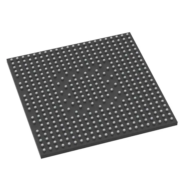
- Part No.:
- STM32MP153DAA1
- Manufacturer:
- STMicroelectronics
- Category:
- Microprocessors
- Package:
- 448-LFBGA
- Datasheet:
-
 STM32MP153DAA1.pdf
- Description:
- IC MPU STM32MP1 800MHZ 448LFBGA
- Quantity:
- Payment:

- Shipping:

Inventory:4,889
Please send an inquiry. Send us your inquiry, and we will respond immediately.
Product details
Overview
STM32MP153DAA1 from STMicroelectronics is a dual-core Arm® Cortex®-A7 (800 MHz) + Cortex®-M4 microprocessor unit (MPU) with TrustZone®, NEON™, and FPU, supporting TFT LCD up to Full HD (1920×1080@30 fps), 37 communication interfaces including dual CAN FD (one TTCAN), and 708 KB on-chip SRAM. It targets industrial HMI, edge gateway, and smart building control systems requiring secure Linux/RTOS coexistence.
For engineers reviewing the STM32MP153DAA1 datasheet, STM32MP153DAA1 pinout, STM32MP153DAA1 application, or STM32MP153DAA1 equivalent, key selection criteria include dual-core isolation via TrustZone®, DDR3/LPDDR3 memory controller support, HDMI-CEC and SPDIF Rx capability, and 2 µA Standby current with DDR retention - critical for battery-backed edge nodes.
Technical Context
The device integrates two independent processing domains: the Cortex-A7 cluster runs Linux-based applications with AXI/AHB interconnects (266 MHz / 209 MHz), while the Cortex-M4 handles real-time tasks with deterministic latency and dedicated DMA routing. Memory subsystem includes 256 KB AXI SYSRAM, 384 KB AHB SRAM, and 64 KB backup-domain SRAM with 4 KB retention SRAM.
Security is enforced via hardware-level TrustZone peripherals, ETZPC, TZC, active tamper detection, and BSEC-managed OTP fuses (3072-bit, including 96-bit unique ID). Clocking uses five fractional PLLs, internal 64 MHz HSI and 32 kHz LSI oscillators, plus external 8–48 MHz HSE and 32.768 kHz LSE sources.
Key Specifications
| Parameter | Value and Actual Design Meaning |
|---|---|
| Cores | Dual Arm® Cortex®-A7 @ 800 MHz + single Cortex®-M4 @ 209 MHz - enables Linux + RTOS partitioning with hardware-isolated memory and peripherals. |
| Memory Interface | LPDDR2/LPDDR3-1066 or DDR3/DDR3L-1066 up to 1 Gbyte - supports high-bandwidth graphics and application data streaming. |
| SRAM | 708 KB total: 256 KB AXI SYSRAM (cache-coherent), 384 KB AHB SRAM, 64 KB Backup domain + 4 KB RETRAM - enables fast boot, secure context storage, and RTC-persistent state. |
| Graphics | LCD-TFT controller with dual layer, programmable LUT, up to 90 MHz pixel clock - drives WXGA (1366×768@60 fps) or Full HD (1920×1080@30 fps) displays without external GPU. |
| Communication | 2 × CAN FD (1 × TTCAN), 6 × I²C FM+, 4 × UART/USART, 6 × SPI, 4 × SAI, SPDIF Rx (4 inputs), HDMI-CEC, GMAC (10/100/1000 Mbps) - meets industrial fieldbus, audio, and time-sensitive networking requirements. |
| Analog | 2 × 16-bit ADC (up to 3.6 Msps), 2 × 12-bit DAC (1 MHz), DFSDM (8 channels), temp sensor - supports precision sensor fusion and closed-loop analog control. |
| Power | 1.71–3.6 V I/O supply (5 V-tolerant), 2 µA Standby current with DDR retention - enables ultra-low-power operation in always-on edge devices. |
Pinout & Package
STM32MP153DAA1 is housed in a TFBGA361 package (12 mm × 12 mm, 0.5 mm pitch), compliant with ECOPACK2 environmental standards. Pin assignment follows ST's documented ball map (DS12502 Rev 9, Section 4), with dedicated power domains (VDDCORE, VDDIO, VDDUSB, VDDA), multiple I/O banks (GPIOA–GPIOH), and dedicated high-speed interface lanes (DDR, SDMMC, GMAC, DCMI).
| Pin/Terminal | Circuit Role | Design Meaning |
|---|---|---|
| VDDCORE | Core power supply | 1.1 V nominal supply for Cortex-A7/M4 cores and L2 cache - requires low-noise regulation and decoupling per ST layout guidelines. |
| VDDIO_1–VDDIO_5 | I/O power domains | Independent 1.71–3.6 V supplies per GPIO bank - enables mixed-voltage interfacing (e.g., 1.8 V SDIO, 3.3 V UART) and level-shifting flexibility. |
| NRST | System reset input | Active-low asynchronous reset controlling entire SoC - compatible with push-button, PMIC, or watchdog assertion. |
| BOOT0/BOOT1 | Boot mode selection | Strapped pins determining primary boot source (FSMC, QSPI, SDMMC, USB, etc.) - defines firmware loading path at power-up. |
| OSC_IN/OSC_OUT | HSE oscillator connection | 8–48 MHz crystal interface for high-accuracy system clock - used by RCC to generate CPU, peripheral, and USB clocks. |
| PA0–PH15 | General-purpose I/O | 176 total GPIOs with interrupt, wakeup, and tamper capability - supports multiplexed functions (AF0–AF15) across all communication and timer peripherals. |
Key Features
| Feature | Design Value |
|---|---|
| TrustZone-enabled dual-core architecture | Hardware-enforced isolation between Linux (A7) and real-time firmware (M4), enabling secure boot, encrypted firmware updates, and peripheral access control. |
| Integrated DDR controller with ECC | Supports LPDDR2/LPDDR3/DDR3/DDR3L with configurable bus width (16/32-bit) and up to 8-bit ECC - ensures data integrity in mission-critical memory operations. |
| Multi-protocol audio interface | 4 × SAI (I²S/PDM/SPDIF Tx), SPDIF Rx (4-channel), and internal audio PLL - eliminates need for external audio codecs in voice-enabled HMI and conferencing endpoints. |
| Hardware security accelerators | HASH (SHA-256), HMAC, 2 × TRNG (3-oscillator design), CRC units - accelerates TLS handshake, firmware signature verification, and secure key generation. |
| Low-power retention modes | Standby mode with DDR retention at 2 µA, LPLV-Stop mode with 16 KB SRAM retention - extends battery life in portable HMIs and remote sensors without full reboot. |
Applications
| Industrial HMI | Edge Gateway |
|---|---|
Use Scenario: Touchscreen panel in factory automation cabinet with local logic execution and cloud connectivity. IC Role / Device Role / Timing Role: MPU running Yocto Linux for GUI rendering (LTDC), real-time motion control via M4, and dual CAN FD for PLC communication. Use Value: Single-chip integration reduces BOM count and PCB area; TrustZone isolates safety-critical motion control from network-facing Linux stack. |
Use Scenario: Smart building node aggregating Modbus, BACnet, and BLE sensor data before forwarding to cloud via Ethernet or USB host. IC Role / Device Role / Timing Role: Dual-core processor hosting protocol gateways (A7) and deterministic sensor polling/firmware update scheduling (M4). Use Value: 37 communication interfaces eliminate external bridge ICs; GMAC with IEEE 1588v2 enables precise time synchronization across HVAC subsystems. |
| Medical Display Terminal | Automotive Infotainment Prototype |
Use Scenario: Portable ultrasound display unit requiring high-resolution imaging, touch UI, and battery-backed operation. IC Role / Device Role / Timing Role: Graphics controller (LTDC) driving 1080p display, M4 managing ADC sampling and beamforming, DFSDM processing sigma-delta sensor data. Use Value: 90 MHz pixel clock and dual-layer composition enable smooth overlay of diagnostic overlays; 2 µA Standby preserves battery during idle periods. |
Use Scenario: In-vehicle infotainment development platform supporting HDMI video output, USB media playback, and CAN FD diagnostics. IC Role / Device Role / Timing Role: Application processor (A7) running Android Automotive OS, M4 handling CAN FD message filtering and TTCAN time-triggered scheduling. Use Value: Integrated TTCAN satisfies ASAM MCD-2 MC timing requirements; HDMI-CEC enables seamless TV/AVR control without additional transceivers. |
Equivalent & Alternatives
The following parts are listed as comparable options for similar dual-core MPU applications.
| Alternative Part | Technical Difference | Application Difference | Selection Advice |
|---|---|---|---|
| NXP i.MX 8M Mini (LPC55S69) | Quad-core Cortex-A53 + Cortex-M4F; lacks TrustZone-peripheral isolation and integrated LTDC; no built-in HDMI-CEC or SPDIF Rx. | Better raw A53 performance but higher power; requires external display controller and audio codec for equivalent HMI functionality. | Select when prioritizing Linux application throughput over integrated graphics/audio and security-hardened peripheral partitioning. |
| Renesas RZ/G2L (R9A07G043L2) | Dual Cortex-A55 + Cortex-M33; includes DRAM controller and LVDS output but no native HDMI-CEC or TTCAN; lower SRAM (512 KB vs 708 KB). | Strong multimedia acceleration (VPU) but limited real-time determinism; no hardware tamper detection or 2 µA Standby mode. | Select for video-centric edge AI inference where VPU offload outweighs need for ultra-low-power retention and industrial fieldbus support. |
Compared with i.MX 8M Mini and RZ/G2L, STM32MP153DAA1 uniquely combines TrustZone-peripheral enforcement, integrated TFT controller with 90 MHz pixel clock, dual CAN FD with TTCAN, and sub-µA standby - making it optimal for cost-sensitive, security-aware industrial HMIs requiring minimal external components.
Availability
STM32MP153DAA1 is available at Aetrix Electronics and suitable for industrial HMI, edge gateway, medical display terminal, and automotive infotainment prototype applications requiring stable component supply, long-term lifecycle assurance, and ECOPACK2-compliant packaging.
Supply support for STM32MP153DAA1 includes scheduled delivery planning, volume procurement assistance, BOM continuity management, traceable sourcing, and lifecycle availability coordination for OEM customers, industrial embedded developers, connected-device designers, and electronics production programs.
Manufacturer
STMicroelectronics is a global semiconductor leader headquartered in Geneva, Switzerland, specializing in microcontrollers, power management, sensors, and automotive ICs with strong focus on industrial and embedded markets.
The STM32MP series is designed specifically for heterogeneous computing in resource-constrained edge devices, balancing Linux-capable application processing with real-time MCU responsiveness and hardware-enforced security - targeting industrial automation, smart infrastructure, and human-machine interface applications.
FAQ
What boot sources does STM32MP153DAA1 support?
STM32MP153DAA1 supports eight primary boot sources selected via BOOT0/BOOT1 straps: Quad-SPI flash, SD/eMMC, NAND flash via FMC, USB device, serial flash via SPI, and internal ROM. Each source maps to a specific memory region and initializes the first-stage bootloader (FSBL) in the Cortex-M4, which then loads the second-stage bootloader (SSBL) for the Cortex-A7 cluster.
Does STM32MP153DAA1 support DDR3L memory?
Yes, STM32MP153DAA1 supports DDR3L-1066 at 16-bit or 32-bit bus width, with configurable timing parameters and on-die termination. The DDR controller includes hardware-calibrated write leveling and read leveling, and supports self-refresh, power-down, and deep power-down modes - validated per JEDEC JESD79-3F specification.
How is TrustZone implemented on this MPU?
TrustZone is implemented through three hardware blocks: the TrustZone Address Space Controller (TZC) for DDR memory region protection, the Embedded TrustZone Protection Controller (ETZPC) for peripheral access control, and the Cortex-A7 Security Extensions for secure/non-secure world switching. Secure world code executes only on designated memory regions and cannot access non-secure peripherals without explicit permission via SMC calls.
What is the maximum camera interface bandwidth supported?
The Digital Camera Interface (DCMI) supports up to 140 Mbyte/s throughput with 8–14-bit parallel input, enabling 1080p30 capture from CMOS sensors. It includes embedded frame synchronization, vertical/horizontal blanking detection, and automatic cropping - verified with ON Semiconductor AR0135 and Sony IMX290 sensors in ST reference designs.
STM32MP153DAA1 Specifications
- Product attributes
- Attribute value
- Manufacturer:
- STMicroelectronics
- Package/Case:
- 448-LFBGA
- Series:
- STM32MP1
- Packaging:
- Tray
- Product Status:
- Active
- Core Processor:
- ARM® Cortex®-A7
- Number of Cores/Bus Width:
- 2 Core, 32-Bit
- Speed:
- 209MHz, 800MHz
- Co-Processors/DSP:
- ARM® Cortex®-M4
- RAM Controllers:
- DDR3, DDR3L, LPDDR2, LPDDR3
- Graphics Acceleration:
- Yes
- Display & Interface Controllers:
- HDMI-CEC, LCD
- Ethernet:
- 10/100Mbps (1)
- SATA:
- -
- USB:
- USB 2.0 (2), USB 2.0 OTG+ PHY (3)
- Voltage - I/O:
- 2.5V, 3.3V
- Operating Temperature:
- -20°C ~ 105°C (TJ)
- Grade:
- -
- Qualification:
- -
- Security Features:
- ARM TZ
- Mounting Type:
- Surface Mount
- Supplier Device Package:
- 448-LFBGA (18x18)
- Additional Interfaces:
- CAN, Ethernet, I2C, MMC/SD/SDIO, SPDIF, SPI, UART, USB
STM32MP153DAA1 FAQ
1.How can I place an order for STM32MP153DAA1 through Aetrix?
Please submit a Request for Quotation (RFQ) for STM32MP153DAA1 on Aetrix. Our sales agent will provide a competitive quotation and guide you through the order confirmation once you accept the terms.
2.Are the price and stock information for STM32MP153DAA1 reliable?
The price and inventory of STM32MP153DAA1 are updated periodically and may fluctuate due to market conditions. Stock and pricing data are typically refreshed every 24 hours. Quotation validity for STM32MP153DAA1 is usually 5 days.
3.What payment methods are accepted for STM32MP153DAA1?
We accept Wire Transfer, PayPal, Credit Card, Western Union, MoneyGram, and Escrow for STM32MP153DAA1 transactions.
Note: Certain payment methods may incur a processing fee.
4.How is shipping managed for STM32MP153DAA1?
STM32MP153DAA1 orders can be shipped via leading logistics carriers, including DHL, UPS, FedEx, TNT, or Registered Mail.
Once your STM32MP153DAA1 order is processed, you will receive an email with the shipment details and tracking number.
Note: Tracking information may take up to 24 hours to appear. Express delivery typically takes 3–5 business days.
5.How can I obtain technical support or documentation for STM32MP153DAA1?
For technical support, including STM32MP153DAA1 datasheets, pinout diagrams, or application guidance, please contact our engineering support team. They can provide detailed documentation and assistance for your STM32MP153DAA1 requirements.
6.How does Aetrix verify that STM32MP153DAA1 is sourced from the original manufacturer or authorized distributors?
All STM32MP153DAA1 products on Aetrix are procured from qualified distributors and authorized channels. Our dedicated quality assurance team conducts strict verification, including traceability checks and, if necessary, third-party testing. This ensures that STM32MP153DAA1 meets industry standards.
7.What is the process for return or replacement of STM32MP153DAA1?
All STM32MP153DAA1 units undergo pre-shipment inspection (PSI). If there is an issue with STM32MP153DAA1, returns or replacements are accepted under the following conditions:
1.Quantity discrepancies, incorrect items, or visible external defects (such as breakage or corrosion), acknowledged by Aetrix.
2.The issue is reported within 90 days of delivery.
3.The STM32MP153DAA1 part is unused and in its original packaging.
Return procedure for STM32MP153DAA1:
1.Submit a request within 90 days.
2.Obtain a Return Material Authorization (RMA) from Aetrix.
STM32MP153DAA1 Tags

-
AT91SAM9260B-CU-999
Microchip Technology
-
AT91SAM9G25-CU
Microchip Technology

-
ATSAMA5D27C-CU
Microchip Technology
-
AT91SAM9X35-CU
Microchip Technology
-
AT91SAM9X25-CU
Microchip Technology

-
MCIMX6Y2CVM08AB
NXP Semiconductors
.JPG)
-
AM3352BZCZ100
Texas Instruments
-
AT91SAM9260B-CU
Microchip Technology

-
AT91SAM9260B-QU
Microchip Technology

-
ATSAMA5D31A-CU
Microchip Technology
-
AT91SAM9G20B-CU-999
Microchip Technology
-
MCIMX6Y2CVM05AB
NXP Semiconductors
Tech Hub

A practical engineering guide to 3.3V and 5V logic compatibility, input thresholds, resistor dividers, translator ICs, MOSFET level shifting, I2C pull-ups, timing limits and power-sequencing risks.

The 74HC595 uses push-pull logic outputs, while the TPIC6B595 uses 50 V open-drain DMOS sinks for higher-power loads. This guide compares timing, current limits, 3.3 V interfacing, load wiring, thermal…

The 74HC595 converts serial data into eight stable parallel outputs. This guide covers pin functions, shift and storage timing, OE and MR behavior, drive-current limits, cascading, voltage compatibilit…

A technical comparison of level-sensitive latches and edge-triggered flip-flops, covering timing windows, setup and hold limits, master–slave operation, time borrowing, race-through, HDL inference and…

A D latch stores one bit while Enable controls when data can pass. This reference covers gate-level operation, truth tables, transparency, setup and hold timing, LE versus OE, common ICs and practical …

An SR latch stores one bit through cross-coupled feedback. This engineering reference covers NOR and NAND implementations, truth tables, forbidden-state recovery, gated operation, switch debouncing, fa…

Latch circuits retain one bit through feedback. This technical reference covers SR and D latches, truth tables, transparency, timing limits, latch-versus-flip-flop behavior, applications and common log…

An engineering guide to LED driver operation, constant-current and constant-voltage outputs, linear and switching topologies, dimming, IC selection, calculations, replacement compatibility, and fault c…

Operational amplifier guide covering op amp basics, feedback, ideal vs real op amps, common configurations, buffer circuits, offset, bias current, gain-bandwidth, slew rate, rail-to-rail limits and sel…

Jumper cables guide covering safe connection order, red and black clamp placement, final ground connection, cable gauge, length, clamp quality, copper vs CCA cables, jump starter comparison and battery…


