
 My Inquiry
 My Account


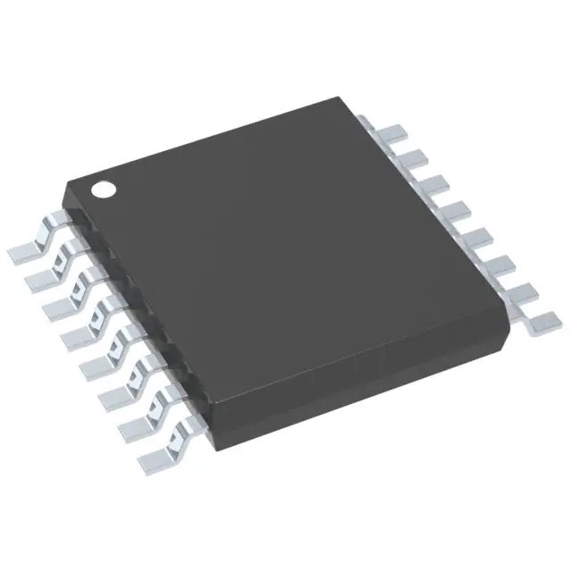
STMicroelectronics STP08DP05XTTR
- Part No.:
- STP08DP05XTTR
- Manufacturer:
- STMicroelectronics
- Category:
- LED Drivers
- Package:
- 16-TSSOP (0.173", 4.40mm Width) Exposed Pad
- Datasheet:
-
 STP08DP05XTTR.pdf
- Description:
- IC LED DRVR LIN 100MA 16HTSSOP
- Quantity:
- Payment:

- Shipping:

Inventory:50,832
Please send an inquiry. Send us your inquiry, and we will respond immediately.
Product details
Overview
STP08DP05XTTR from STMicroelectronics is an 8-bit constant-current LED sink driver with integrated open/short output error detection, designed for LED panel displays and signage systems. It delivers 5–100 mA per channel via external REXT, supports 30 MHz serial clocking, operates from 3.0–5.5 V supply, and features dual-mode pin functionality (LE/DM1 and OE/DM2) for seamless detection mode entry without additional pins.
For engineers reviewing the STP08DP05XTTR datasheet, STP08DP05XTTR pinout, STP08DP05XTTR application, or STP08DP05XTTR equivalent, key selection considerations include its 8-channel sink architecture, thermal-enhanced TSSOP-16 exposed-pad package, real-time fault reporting via SDO, adjustable current accuracy (±1.5% between bits), and compatibility with 3.3 V microcontrollers in high-density LED matrix designs.
Technical Context
The STP08DP05XTTR integrates an 8-bit serial-in/parallel-out shift register cascaded with an 8-bit D-type storage latch, feeding eight matched, thermally stable current-regulated sinks. Its detection logic uses a three-phase sequence on OE/DM2 and LE/DM1 to enter error mode-sampling open, short-to-GND, and short-to-VO conditions without interrupting normal data flow.
Each output provides up to 20 V compliance voltage, enabling series-connected LEDs per channel; current is set by a single external resistor (REXT) with typical accuracy of ±1.5% between channels at VO ≥ 1.3 V. The device implements thermal shutdown at ~170 °C and offers ESD protection rated at 2.5 kV HBM and 200 V MM.
Key Specifications
| Parameter | Value and Actual Design Meaning |
|---|---|
| Output channels | 8 independent constant-current sinks, each programmable 5–100 mA via REXT |
| Supply voltage | 3.0–5.5 V - enables direct interface with 3.3 V microcontrollers and low-voltage systems |
| Max output voltage | 20 V - supports driving up to 6 standard red LEDs (3.2 V each) in series per channel |
| Serial clock frequency | 30 MHz - sustains high-speed LED refresh rates for flicker-free full-color panels |
| Current accuracy | ±1.5% between outputs at VO ≥ 1.3 V - ensures uniform brightness across LED arrays |
| Error detection | Detects open, short-to-GND, and short-to-VO per channel - reports results serially via SDO |
| Thermal resistance | RthJA = 37.5 °C/W (exposed pad soldered) - enables >2× power dissipation vs standard TSSOP |
Pinout & Package
STP08DP05XTTR is housed in a thermally enhanced HTSSOP-16 (TSSOP-16 exposed pad) package. The exposed pad must be electrically connected to PCB ground or isolated metal land for optimal thermal performance.
| Pin/Terminal | Circuit Role | Design Meaning |
|---|---|---|
| 1 GND | Ground reference | Common return path for all internal circuits and output current sinks |
| 2 SDI | Serial data input | Accepts 8-bit LED on/off pattern; cascades to next device's SDI when multiple ICs are daisy-chained |
| 3 CLK | Serial clock input | Drives shift register on rising edge; supports up to 30 MHz for fast LED updates |
| 4 LE/DM1 | Latch input / Detection Mode 1 control | Latches shifted data to outputs; initiates detection mode entry when pulsed per defined 5-cycle sequence |
| 5–12 OUT0–OUT7 | Constant-current sink outputs | Each drives LED cathodes with regulated current; 20 V max compliance allows series LED strings |
| 13 OE/DM2 | Output enable / Detection Mode 2 control | Active-low output enable; second control signal for entering/resuming detection mode |
| 14 SDO | Serial data output | Shifts out 8-bit error status (1 bit per channel) during detection mode; compatible with MCU SPI input |
| 15 R-EXT | Current-setting resistor connection | Connects external resistor to set all 8 output currents simultaneously; range: 124 Ω–6.74 kΩ |
| 16 VDD | Positive supply | 3.0–5.5 V power rail; powers logic and current regulation circuitry |
Key Features
| Feature | Design Value |
|---|---|
| Backward-compatible footprint | Pin-for-pin and functional replacement for STP8C/L596 - simplifies legacy display upgrades |
| Integrated fault diagnostics | Detects open, short-to-GND, and short-to-VO per channel without external components or extra pins |
| Thermally optimized package | TSSOP-16 with exposed pad reduces RthJA to 37.5 °C/W - enables 2.5× higher continuous power vs standard TSSOP |
| Brightness control flexibility | 0–100% LED dimming via PWM on OE/DM2 pin, plus analog current adjustment via REXT |
| High-speed serial interface | 30 MHz clock tolerance supports >2.4 Mbps data throughput - sufficient for 1920×1080 LED video refresh |
Applications
| LED Video Wall Panels | Industrial Status Displays |
|---|---|
|
Use Scenario: High-resolution indoor LED video walls requiring uniform brightness, real-time fault reporting, and thermal resilience in compact enclosures. IC Role / Device Role / Timing Role: 8-bit constant-current sink driver with serial cascade capability and per-channel open/short detection. Use Value: Enables automatic identification of failed LED segments without manual inspection, reducing maintenance downtime by >70% in large-scale installations. |
Use Scenario: Factory floor operator dashboards using monochrome LED arrays for machine status, alarms, and process indicators. IC Role / Device Role / Timing Role: LED driver with robust 3.3 V microcontroller interface and latch-controlled static display update. Use Value: Eliminates need for external current-limiting resistors and discrete fault monitoring circuitry - cuts BOM count by 12+ parts per display module. |
| Transportation Signage | Architectural LED Facades |
|
Use Scenario: Outdoor bus/train station signs operating across -40 °C to +85 °C ambient, subject to vibration and moisture exposure. IC Role / Device Role / Timing Role: Thermally rugged LED sink with 20 V output compliance and ESD-hardened I/O (2.5 kV HBM). Use Value: Maintains consistent LED luminance despite wide temperature swings and eliminates field failures due to undetected open-circuit LED strings. |
Use Scenario: Dynamic architectural lighting systems requiring synchronized multi-channel dimming and long cable runs to remote LED modules. IC Role / Device Role / Timing Role: Serial-in/parallel-out driver supporting daisy-chained topology and 30 MHz clock for low-latency global updates. Use Value: Reduces inter-module wiring by 80% vs parallel control schemes and supports >50 m cable lengths with minimal signal degradation. |
Equivalent & Alternatives
The following parts are listed as comparable options for similar LED sink driver applications.
| Alternative Part | Technical Difference | Application Difference | Selection Advice |
|---|---|---|---|
| TLC59283RTJR | 16-channel, no built-in open/short detection; requires external fault monitoring circuitry | Suitable for cost-sensitive, non-critical LED arrays where diagnostics are handled at system level | Select when channel count >8 is required and diagnostic coverage is managed externally |
| MAX7219CWG+ | Integrated 8×8 LED matrix controller with SPI interface; includes scan driver and brightness DAC | Designed for fixed-grid alphanumeric displays, not general-purpose LED string driving | Select only for 64-LED dot-matrix applications with built-in decoding and multiplexing |
Compared with TLC59283RTJR and MAX7219CWG+, the STP08DP05XTTR uniquely combines per-channel fault detection, 20 V output compliance, and thermal-enhanced packaging - making it optimal for reliability-critical, high-density LED signage where failure isolation and thermal margin are design priorities.
Availability
STP08DP05XTTR is available at Aetrix Electronics and suitable for LED video walls, industrial status displays, and transportation signage requiring stable component supply, long-term lifecycle support, and traceable sourcing for production programs.
Supply support for STP08DP05XTTR includes scheduled delivery planning, volume procurement assistance, BOM continuity management, traceable sourcing, and lifecycle availability coordination for OEM customers, industrial embedded developers, connected-device designers, and electronics production programs.
Manufacturer
STMicroelectronics is a global semiconductor leader headquartered in Geneva, Switzerland, specializing in automotive, industrial, and power management solutions with over 45 years of analog and mixed-signal IC expertise.
The STP08DP05XTTR belongs to ST's LED driver portfolio, engineered specifically for high-reliability, thermally constrained LED display systems requiring integrated diagnostics and scalable serial architecture.
FAQ
What is the minimum REXT value supported, and what output current does it produce?
The minimum recommended REXT is 124 Ω, which sets the maximum output current to 130 mA per channel at VDD = 5 V and TA = 25 °C. This value is validated in the datasheet's Figure 11 and Table 10. Operation above 100 mA is possible but requires careful thermal derating due to increased power dissipation in the exposed-pad package.
How does the device report open-circuit faults, and what MCU interface is required?
Open-circuit faults are reported as logic '0' bits shifted out via the SDO pin during detection mode - one bit per channel (OUT0–OUT7). The MCU must execute the 5-cycle OE/DM2 and LE/DM1 sequence, then read 8 bits from SDO using standard SPI or GPIO bit-banging. No additional ADC or comparator circuitry is needed.
Can STP08DP05XTTR drive RGB LEDs, and what is the maximum number per channel?
Yes - each OUTx channel can drive a series string of monochrome LEDs. With 20 V output compliance and typical forward voltages of 2.0–3.5 V, up to 6 red (2.0 V), 5 green (2.2 V), or 5 blue (3.2 V) LEDs can be driven per channel. RGB pixel control requires three STP08DP05XTTRs (one per color) or multiplexed sequencing.
Is the exposed thermal pad electrically isolated, and how should it be connected on the PCB?
The exposed pad is internally connected to GND and must be soldered to a dedicated PCB copper pour tied to the system ground plane. Per Figure 1 and Table 16, this connection is mandatory to achieve the specified RthJA = 37.5 °C/W. Leaving it floating or connecting to a non-ground net degrades thermal performance and risks device overheating under full load.
STP08DP05XTTR Specifications
- Product attributes
- Attribute value
- Manufacturer:
- STMicroelectronics
- Series:
- -
- Package/Case:
- 16-TSSOP (0.173", 4.40mm Width) Exposed Pad
- Packaging:
- Tape & Reel (TR)
- Product Status:
- Active
- Type:
- Linear
- Topology:
- Shift Register
- Internal Switch(s):
- Yes
- Number of Outputs:
- 8
- Voltage - Supply (Min):
- 3V
- Voltage - Supply (Max):
- 5.5V
- Voltage - Output:
- 20V
- Current - Output / Channel:
- 100mA
- Frequency:
- 30MHz
- Dimming:
- -
- Applications:
- -
- Operating Temperature:
- -40°C ~ 125°C (TA)
- Grade:
- -
- Qualification:
- -
- Mounting Type:
- Surface Mount
- Supplier Device Package:
- 16-HTSSOP
STP08DP05XTTR FAQ
1.How can I place an order for STP08DP05XTTR through Aetrix?
Please submit a Request for Quotation (RFQ) for STP08DP05XTTR on Aetrix. Our sales agent will provide a competitive quotation and guide you through the order confirmation once you accept the terms.
2.Are the price and stock information for STP08DP05XTTR reliable?
The price and inventory of STP08DP05XTTR are updated periodically and may fluctuate due to market conditions. Stock and pricing data are typically refreshed every 24 hours. Quotation validity for STP08DP05XTTR is usually 5 days.
3.What payment methods are accepted for STP08DP05XTTR?
We accept Wire Transfer, PayPal, Credit Card, Western Union, MoneyGram, and Escrow for STP08DP05XTTR transactions.
Note: Certain payment methods may incur a processing fee.
4.How is shipping managed for STP08DP05XTTR?
STP08DP05XTTR orders can be shipped via leading logistics carriers, including DHL, UPS, FedEx, TNT, or Registered Mail.
Once your STP08DP05XTTR order is processed, you will receive an email with the shipment details and tracking number.
Note: Tracking information may take up to 24 hours to appear. Express delivery typically takes 3–5 business days.
5.How can I obtain technical support or documentation for STP08DP05XTTR?
For technical support, including STP08DP05XTTR datasheets, pinout diagrams, or application guidance, please contact our engineering support team. They can provide detailed documentation and assistance for your STP08DP05XTTR requirements.
6.How does Aetrix verify that STP08DP05XTTR is sourced from the original manufacturer or authorized distributors?
All STP08DP05XTTR products on Aetrix are procured from qualified distributors and authorized channels. Our dedicated quality assurance team conducts strict verification, including traceability checks and, if necessary, third-party testing. This ensures that STP08DP05XTTR meets industry standards.
7.What is the process for return or replacement of STP08DP05XTTR?
All STP08DP05XTTR units undergo pre-shipment inspection (PSI). If there is an issue with STP08DP05XTTR, returns or replacements are accepted under the following conditions:
1.Quantity discrepancies, incorrect items, or visible external defects (such as breakage or corrosion), acknowledged by Aetrix.
2.The issue is reported within 90 days of delivery.
3.The STP08DP05XTTR part is unused and in its original packaging.
Return procedure for STP08DP05XTTR:
1.Submit a request within 90 days.
2.Obtain a Return Material Authorization (RMA) from Aetrix.
STP08DP05XTTR Tags

-
BCR402RE6327HTSA1
Infineon Technologies

-
BCR430UXTSA2
Infineon Technologies

-
BCR420UE6433HTMA1
Infineon Technologies
-
BCR420UE6327HTSA1
Infineon Technologies
-
BCR421UE6327HTSA1
Infineon Technologies

-
LYT1604D-TL
Power Integrations

-
HV9910CLG-G
Microchip Technology

-
CL2N8-G
Microchip Technology

-
BCR420UW6-7
Diodes Incorporated
-
BCR421UW6-7
Diodes Incorporated

-
BCR420UFD-7
Diodes Incorporated
-
BCR421UFD-7
Diodes Incorporated
Tech Hub

Jumper cables guide covering safe connection order, red and black clamp placement, final ground connection, cable gauge, length, clamp quality, copper vs CCA cables, jump starter comparison and battery…

LDO regulator guide covering low dropout voltage, power dissipation, thermal design, PSRR, output noise, capacitor stability, adjustable LDO circuits, LDO vs buck converter and datasheet selection chec…

Conditional Access Module guide covering CAM meaning, CI/CI+ interface, smart card authorization, DVB security workflow, TV and set-top box compatibility, internal electronics, ESD protection, connecto…

Guide to electronic component obsolescence covering EOL risk, PCN/PDN notices, last-time buy planning, replacement options, form-fit-function validation, counterfeit risk and BOM lifecycle management.

18650 battery guide covering lithium-ion cell basics, 3.6V/3.7V voltage, 4.2V charging, mAh and Wh capacity, protected cells, chargers, BMS, series-parallel packs, holders, welding and sourcing checks.…

Hall effect sensor guide covering working principle, linear and digital sensors, Arduino circuits, current sensing, speed detection, automotive applications, A3144 examples, signal filtering and datash…

Product Change Notification guide for electronic components, covering PCN meaning, PCN vs PDN/EOL, common change types, risk levels, form-fit-function review, engineering validation, BOM control, LTB/L…

A practical guide to blend door actuators, covering HVAC function, symptoms, location, AC and heater issues, reset and calibration, replacement cost, electrical diagnosis, compatibility checks, and rep…

Engineering guide to Raspberry Pi alternatives, covering chip-level differences, Orange Pi, ROCK, Jetson, Banana Pi, NanoPi, Compute Module, Pico, GPIO, camera, HAT compatibility, and replacement risks…

Engineering guide to dynamic load response testing for high-current buck converters, covering load step setup, slew rate, Vcore undershoot, overshoot, recovery time, probe location, output capacitors a…


