
 My Inquiry
 My Account


STMicroelectronics STSPIN220
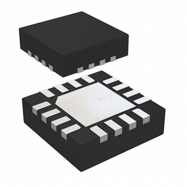
- Part No.:
- STSPIN220
- Manufacturer:
- STMicroelectronics
- Category:
- Motor Drivers, Controllers
- Package:
- 16-VFQFN Exposed Pad
- Datasheet:
-
 STSPIN220.pdf
- Description:
- LOW VOLTAGE STEPPER MOTOR DRIVER
- Quantity:
- Payment:

- Shipping:

Inventory:26,894
Please send an inquiry. Send us your inquiry, and we will respond immediately.
Product details
Overview
STSPIN220 from STMicroelectronics is a low-voltage, 1.3 A RMS stepper motor driver IC with integrated microstepping sequencer (up to 1/256-step), PWM current control, and dual full-bridge power stage in VFQFPN 3×3×1.0 mm package. It operates from 1.8 V to 10 V, delivers <80 nA standby current, and features non-dissipative overcurrent, short-circuit, and thermal shutdown protection - designed for pop-up camera actuators and portable POS devices.
For engineers reviewing the STSPIN220 datasheet, STSPIN220 pinout, STSPIN220 application, or STSPIN220 equivalent, key selection criteria include microstepping resolution (1/256), RDS(ON) (0.4 Ω typ.), TOFF programmability, EN/FAULT open-drain fault signaling, and STBY-driven zero-consumption mode for battery longevity.
Technical Context
The STSPIN220 implements two independent PWM current controllers with fixed OFF-time modulation, where decay timing is split into 5/8 slow decay and 3/8 quasi-synchronous fast decay phases. The internal 10-bit microstepping sequencer latches MODE1–MODE4 at power-up or STBY exit to configure step resolution, while DIR and STCK pins drive direction and clocked stepping.
Protection logic includes real-time current sensing via SENSEA/SENSEB pins, comparator-based non-dissipative overcurrent detection (2 A threshold), and thermal shutdown at 160 °C with 40 °C hysteresis. The EN/FAULT pin serves dual role: enable input and open-drain fault indicator tied to external REN/CEN network for configurable fault recovery timing.
Key Specifications
| Parameter | Value and Actual Design Meaning |
|---|---|
| Supply voltage range | 1.8 V to 10 V - supports single-cell Li-ion and multi-cell alkaline battery systems without LDO pre-regulation. |
| Max output current | 1.3 A RMS per bridge - sufficient for NEMA 8–11 size stepper motors in compact portable applications. |
| RDS(ON) (HS + LS) | 0.4 Ω typ. at 10 V - minimizes conduction loss and self-heating in high-duty-cycle microstepping modes. |
| Microstepping resolution | Up to 1/256-step - enables ultra-smooth motion and reduced vibration in precision optical positioning (e.g., smartphone camera focus). |
| Standby current | <80 nA - extends battery life in always-on standby states such as POS device sleep mode or robotic idle periods. |
| Thermal shutdown | 160 °C with 40 °C hysteresis - prevents latch-up during sustained load or poor PCB thermal design while enabling automatic recovery. |
| TOFF adjustment range | 9 µs to 125 µs via ROFF resistor - allows tuning of current regulation loop bandwidth and torque ripple across motor inductance variations. |
Pinout & Package
VFQFPN 3×3×1.0 mm, 16-lead package with exposed thermal pad (EPAD) requiring direct connection to GND for optimal thermal performance and EMI suppression.
| Pin/Terminal | Circuit Role | Design Meaning |
|---|---|---|
| 1 DIR/MODE4 | Logic input | Direction control during stepping; also latched at startup for microstep mode selection (e.g., 1/256-step when MODE1=MODE2=1). |
| 2 STCK/MODE3 | Logic input | Step clock input; doubles as mode select pin-latched at power-up or STBY exit to configure sequencing behavior. |
| 3 OUTA1, 5 OUTA2, 10 OUTB1, 8 OUTB2 | Power outputs | Four half-bridge terminals forming two full H-bridges driving stepper coil A and B; rated for 1.3 A RMS continuous current. |
| 4 SENSEA, 9 SENSEB | Analog sense inputs | Current-sense nodes connected to external shunt resistors (e.g., 330 mΩ); feed PWM comparators for closed-loop current regulation. |
| 6 VS | Power supply | Main motor supply input (1.8–10 V); powers both logic and power stages; decoupling required per DS11633 layout guidelines. |
| 7, EPAD GND | Ground reference | Primary ground return and thermal path; EPAD must be soldered to large copper pour for RthJCbot = 9.1 °C/W performance. |
| 11 REF | Analog input | Reference voltage (0.1–0.5 V) setting peak coil current; determines full-scale amplitude of sinusoidal microstepping waveform. |
| 12 TOFF | Analog input | External resistor-to-ground sets total OFF time (slow + fast decay); critical for current loop stability and torque consistency. |
| 13 EN/FAULT | Logic input / Open-drain output | Active-low enable; becomes open-drain low on fault (OC, SC, thermal); requires external pull-up for MCU interrupt detection. |
| 14 STBY/RESET | Logic input | Forces zero-consumption state when pulled low; resets internal logic on release; VSTBYL = 0.9 V threshold ensures noise immunity. |
| 15 MODE2, 16 MODE1 | Logic inputs | Mode configuration bits latched at startup; define microstep resolution (e.g., MODE1=1, MODE2=1 → 1/256-step); override DIR/STCK function post-latch. |
Key Features
| Feature | Design Value |
|---|---|
| Programmable microstepping | Configurable up to 1/256-step via MODE pins - eliminates external indexer IC and reduces BOM count in space-constrained designs. |
| Ultra-low standby consumption | <80 nA quiescent current - enables multi-month battery operation in intermittent-use devices like smart retail peripherals. |
| Non-dissipative overcurrent protection | Detects overload without shunt resistor heating - preserves accuracy and avoids thermal drift in long-duration positioning tasks. |
| Integrated dual full-bridge | 0.4 Ω RDS(ON) HS+LS - achieves >85% efficiency at 1.3 A RMS, reducing need for heatsinking in sealed enclosures. |
| TOFF-adjustable PWM control | External ROFF resistor tunes OFF time from 9 µs to 125 µs - adapts current regulation to diverse motor inductances (0.5–10 mH typical). |
Applications
| Pop-up Camera Actuator | Portable Point-of-Sale Terminal |
|---|---|
Use Scenario: Rapid, silent deployment/retraction of smartphone front-facing camera module within mechanical constraints. IC Role / Device Role / Timing Role: Stepper driver executing precise 1/256-step microstepping sequences under DIR/STCK command; STBY enables instant wake-from-sleep activation. Use Value: Eliminates audible coil whine and mechanical jerk, meeting OEM acoustic specs while sustaining >100,000 actuation cycles. |
Use Scenario: Driving paper feed and print head movement in handheld receipt printers powered by 2×AA batteries. IC Role / Device Role / Timing Role: Low-voltage stepper controller managing bidirectional paper advance with stall detection via SENSEA/B feedback. Use Value: Extends battery life to >12 months in typical retail usage due to sub-80 nA standby and efficient 0.4 Ω power stage. |
| PC Peripheral Focus Mechanism | Compact Robotic Joint Control |
Use Scenario: Autofocus actuation in USB-connected webcams and document scanners requiring smooth, jitter-free lens motion. IC Role / Device Role / Timing Role: Microstepping sequencer generating sinusoidal current profiles synchronized to host USB polling intervals. Use Value: Reduces positional error to ±0.5% of full scale across temperature, enabling sub-10 µm focus repeatability. |
Use Scenario: Positioning joints in educational robotics kits using NEMA 8 stepper motors powered by 3.7 V Li-Po packs. IC Role / Device Role / Timing Role: Fault-resilient driver with EN/FAULT reporting over I²C GPIO, enabling autonomous recovery from motor stall events. Use Value: Prevents firmware lockup during jam conditions via hardware-level fault signaling and configurable tDIS recovery timing. |
Equivalent & Alternatives
The following parts are listed as comparable options for similar stepper motor driver applications.
| Alternative Part | Technical Difference | Application Difference | Selection Advice |
|---|---|---|---|
| TMC2130-LA | Higher voltage (4.75–46 V), integrated spreadCycle™ stealthChop, SPI interface; no STBY pin; larger QFN32 package. | Targets industrial automation and 24 V DC systems; lacks ultra-low standby for battery use. | Select when higher bus voltage, advanced noise suppression, or field-oriented control is required - not for sub-10 V portable designs. |
| DRV8834 | Lower max current (1.5 A peak), fixed 1/32 microstepping, no TOFF adjustment, 1.5 V min supply, smaller 3×3 mm QFN. | Suitable for cost-sensitive, lower-resolution applications like basic toy motors or simple linear actuators. | Choose for simpler designs needing only coarse stepping and minimal external components - sacrifices resolution and fine-tuning capability. |
Compared with TMC2130-LA and DRV8834, the STSPIN220 uniquely balances ultra-low-power standby, 1/256 microstepping, and 1.8 V operation - making it the only viable option for long-life, high-precision battery-powered optical positioning.
Availability
STSPIN220 is available at Aetrix Electronics and suitable for pop-up camera actuators, portable POS terminals, and PC peripheral focus mechanisms requiring stable component supply, consistent parametric performance, and long-term lifecycle support.
Supply support for STSPIN220 includes scheduled delivery planning, volume procurement assistance, BOM continuity management, traceable sourcing, and lifecycle availability coordination for OEM customers, industrial embedded developers, connected-device designers, and electronics production programs.
Manufacturer
STMicroelectronics is a global semiconductor leader headquartered in Geneva, Switzerland, specializing in power management, motion control, and microcontrollers for industrial, automotive, and consumer markets.
The STSPIN family targets ultra-compact, energy-efficient motor control - specifically engineered for battery-powered devices where size, thermal envelope, and standby current are primary constraints.
FAQ
What is the minimum supply voltage required for STSPIN220 to operate correctly?
The STSPIN220 requires a minimum VS of 1.45 V to turn on (VSth(ON)), but reliable operation across all microstepping modes and load conditions begins at 1.8 V per datasheet Table 2. Below 1.8 V, current regulation accuracy degrades and thermal margin shrinks significantly due to increased RDS(ON).
How does the STSPIN220 implement non-dissipative overcurrent protection?
It monitors voltage across external sense resistors (SENSEA/SENSEB) using high-speed comparators referenced to internal thresholds. When sensed voltage exceeds the 2 A trip point, the power stage shuts off instantly without engaging dissipative current-limiting circuits - preserving signal integrity and avoiding thermal runaway during short-circuit events.
Can STSPIN220 drive unipolar stepper motors?
No - the STSPIN220 is designed exclusively for bipolar stepper motors with center-tapped or dual-winding configurations. Its dual full-bridge topology requires four independent coil terminals (OUTA1/2, OUTB1/2) and cannot interface with unipolar 5- or 6-wire motor wiring schemes.
What is the recommended PCB layout practice for the EPAD on STSPIN220?
The exposed pad (EPAD) must be soldered to a solid GND plane using ≥4 thermal vias (300 µm diameter) placed within the pad area, connected to an internal or bottom-layer GND pour. This achieves the specified RthJCbot = 9.1 °C/W and prevents junction temperature exceedance above 125 °C under 1.3 A RMS load.
STSPIN220 Specifications
- Product attributes
- Attribute value
- Manufacturer:
- STMicroelectronics
- Series:
- STSPIN2
- Package/Case:
- 16-VFQFN Exposed Pad
- Packaging:
- Tape & Reel (TR)
- Product Status:
- Active
- Motor Type - Stepper:
- Bipolar
- Motor Type - AC, DC:
- -
- Function:
- Driver - Fully Integrated, Control and Power Stage
- Output Configuration:
- Half Bridge (4)
- Interface:
- Step/Direction
- Technology:
- Power MOSFET
- Step Resolution:
- >256 Microsteps
- Applications:
- Battery Powered
- Current - Output:
- 1.3A
- Voltage - Supply:
- 0V ~ 5V
- Voltage - Load:
- 1.8V ~ 10V
- Operating Temperature:
- -40°C ~ 150°C (TJ)
- Grade:
- -
- Qualification:
- -
- Mounting Type:
- Surface Mount
- Supplier Device Package:
- 16-VFQFPN (3x3)
STSPIN220 FAQ
1.How can I place an order for STSPIN220 through Aetrix?
Please submit a Request for Quotation (RFQ) for STSPIN220 on Aetrix. Our sales agent will provide a competitive quotation and guide you through the order confirmation once you accept the terms.
2.Are the price and stock information for STSPIN220 reliable?
The price and inventory of STSPIN220 are updated periodically and may fluctuate due to market conditions. Stock and pricing data are typically refreshed every 24 hours. Quotation validity for STSPIN220 is usually 5 days.
3.What payment methods are accepted for STSPIN220?
We accept Wire Transfer, PayPal, Credit Card, Western Union, MoneyGram, and Escrow for STSPIN220 transactions.
Note: Certain payment methods may incur a processing fee.
4.How is shipping managed for STSPIN220?
STSPIN220 orders can be shipped via leading logistics carriers, including DHL, UPS, FedEx, TNT, or Registered Mail.
Once your STSPIN220 order is processed, you will receive an email with the shipment details and tracking number.
Note: Tracking information may take up to 24 hours to appear. Express delivery typically takes 3–5 business days.
5.How can I obtain technical support or documentation for STSPIN220?
For technical support, including STSPIN220 datasheets, pinout diagrams, or application guidance, please contact our engineering support team. They can provide detailed documentation and assistance for your STSPIN220 requirements.
6.How does Aetrix verify that STSPIN220 is sourced from the original manufacturer or authorized distributors?
All STSPIN220 products on Aetrix are procured from qualified distributors and authorized channels. Our dedicated quality assurance team conducts strict verification, including traceability checks and, if necessary, third-party testing. This ensures that STSPIN220 meets industry standards.
7.What is the process for return or replacement of STSPIN220?
All STSPIN220 units undergo pre-shipment inspection (PSI). If there is an issue with STSPIN220, returns or replacements are accepted under the following conditions:
1.Quantity discrepancies, incorrect items, or visible external defects (such as breakage or corrosion), acknowledged by Aetrix.
2.The issue is reported within 90 days of delivery.
3.The STSPIN220 part is unused and in its original packaging.
Return procedure for STSPIN220:
1.Submit a request within 90 days.
2.Obtain a Return Material Authorization (RMA) from Aetrix.
STSPIN220 Tags

-
DRV2603RUNR
Texas Instruments

-
DRV8837CDSGR
Texas Instruments

-
DRV8837DSGR
Texas Instruments
-
DRV8838DSGR
Texas Instruments

-
DRV8839DSSR
Texas Instruments

-
EMC2301-1-ACZL-TR
Microchip Technology
-
DRV8231ADSGR
Texas Instruments

-
EMC2302-2-AIZL-TR
Microchip Technology

-
DRV8800PWPR
Texas Instruments
-
DRV8835DSSR
Texas Instruments

-
EMC2303-1-KP-TR
Microchip Technology

-
DRV8876PWPR
Texas Instruments
Tech Hub

A practical engineering and sourcing framework covering lifecycle verification, lifetime-buy calculations, replacement qualification, supplier checks and counterfeit-risk controls.

TTL and CMOS logic families differ in thresholds, loading, output drive, power and timing. This engineering guide compares 74HC and 74HCT, calculates noise margins and checks 3.3 V/5 V compatibility.

A practical engineering guide to 3.3V and 5V logic compatibility, input thresholds, resistor dividers, translator ICs, MOSFET level shifting, I2C pull-ups, timing limits and power-sequencing risks.

The 74HC595 uses push-pull logic outputs, while the TPIC6B595 uses 50 V open-drain DMOS sinks for higher-power loads. This guide compares timing, current limits, 3.3 V interfacing, load wiring, thermal…

The 74HC595 converts serial data into eight stable parallel outputs. This guide covers pin functions, shift and storage timing, OE and MR behavior, drive-current limits, cascading, voltage compatibilit…

A technical comparison of level-sensitive latches and edge-triggered flip-flops, covering timing windows, setup and hold limits, master–slave operation, time borrowing, race-through, HDL inference and…

A D latch stores one bit while Enable controls when data can pass. This reference covers gate-level operation, truth tables, transparency, setup and hold timing, LE versus OE, common ICs and practical …

An SR latch stores one bit through cross-coupled feedback. This engineering reference covers NOR and NAND implementations, truth tables, forbidden-state recovery, gated operation, switch debouncing, fa…

Latch circuits retain one bit through feedback. This technical reference covers SR and D latches, truth tables, transparency, timing limits, latch-versus-flip-flop behavior, applications and common log…

An engineering guide to LED driver operation, constant-current and constant-voltage outputs, linear and switching topologies, dimming, IC selection, calculations, replacement compatibility, and fault c…


