
 My Inquiry
 My Account


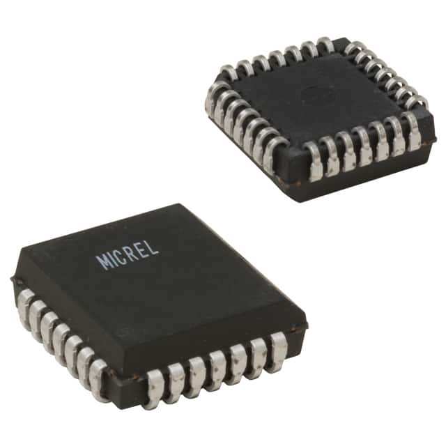
Microchip Technology SY100E101JY
- Part No.:
- SY100E101JY
- Manufacturer:
- Microchip Technology
- Package:
- 28-LCC (J-Lead)
- Datasheet:
-
 SY100E101JY.pdf
- Description:
- IC GATE OR/NOR QUAD 4INP 28PLCC
- Quantity:
- Payment:

- Shipping:

Inventory:4,842
Please send an inquiry. Send us your inquiry, and we will respond immediately.
Product details
Overview
SY100E101JY from Micrel is a quad 4-input ECL OR/NOR gate IC with true and complementary outputs, 500 ps max propagation delay, –4.2 V to –5.5 V VEE operating range, and internal 75 kΩ input pulldown resistors. It operates in industrial temperature range and is used in high-speed timing-critical logic systems such as telecom line cards and test equipment.
For engineers reviewing the SY100E101JY datasheet, SY100E101JY pinout, SY100E101JY application, or SY100E101JY equivalent, key selection criteria include ECL-level compatibility, propagation delay budgeting, skew control in parallel logic paths, and Pb-free PLCC package compliance for new designs.
Technical Context
The SY100E101JY implements four independent 4-input OR/NOR gates in a single ECL device, each producing both non-inverted (Qn) and inverted (Qn̅) outputs simultaneously. Its logic equation is Qn = Dna + Dnb + Dnc + Dnd, with all inputs referenced to VEE and outputs compatible with 10KH/100K ECL I/O levels.
It features two skew specifications: within-device skew ≤50 ps (between identical transitions across different gates), and within-gate skew ≤25 ps (between different input-to-output paths in the same gate), enabling precise timing alignment in multi-channel logic arrays.
Key Specifications
| Parameter | Value and Actual Design Meaning |
|---|---|
| Propagation Delay (tPD) | Max 500 ps (D to Q), critical for sub-2 GHz clock domain logic synchronization |
| VEE Range | –4.2 V to –5.5 V, supports legacy ECL power rails and noise margin optimization |
| Input Pulldown | 75 kΩ internal resistor per input, eliminates need for external biasing on unused inputs |
| Within-Gate Skew | ≤25 ps, ensures matched delay across all four inputs of a single OR/NOR gate |
| Rise/Fall Time (tr/tf) | 300–575 ps (20%–80%), enables clean edge integrity at >1 Gbps data rates |
| Power Supply Current | 30–42 mA (100EL grade), defines thermal load and decoupling requirements |
Pinout & Package
SY100E101JY is housed in a 28-pin Plastic Leaded Chip Carrier (PLCC, J28-1) package with matte-Sn Pb-free finish and industrial temperature rating (–40°C to +85°C).
| Pin/Terminal | Circuit Role | Design Meaning |
|---|---|---|
| Dna–Dnd (Pins 1–4, 6–9, 11–14, 16–19) | Data Inputs (4 groups × 4) | Four independent 4-input logic channels; each group drives one OR/NOR gate pair |
| Q0–Q3 (Pins 20–23) | True Outputs | Active-HIGH ECL outputs; require termination to VCCO (GND) for proper logic level referencing |
| Q0̅–Q3̅ (Pins 24–27) | Complementary Outputs | Active-LOW ECL outputs; enable differential signaling or logic redundancy without external inverters |
| VCCO (Pin 28) | Output Supply Reference | Connected to GND to establish ECL output common-mode voltage; not a power rail |
| VEE (Pin 15) | Negative Supply Rail | Primary bias node for all ECL circuitry; must be stable within –4.2 V to –5.5 V range |
Key Features
| Feature | Design Value |
|---|---|
| True + Complementary Outputs | Each gate delivers Qn and Qn̅ simultaneously, eliminating external inverters in feedback or differential latch paths |
| Internal 75 kΩ Input Pulldowns | Prevents floating inputs in unconnected or dynamically disabled logic paths, reducing noise susceptibility |
| 100K/10KH ECL Compatibility | Interoperates directly with Motorola MC10E/100E101 and other industry-standard ECL families without level-shifting |
| Pb-Free Matte-Sn Finish | Meets RoHS Directive 2011/65/EU and JEDEC J-STD-609A Class 3 moisture sensitivity requirements |
Applications
| Telecom Line Card Logic | High-Speed Test Equipment |
|---|---|
Use Scenario: Signal routing and arbitration logic in OC-48/STM-16 interface modules requiring deterministic sub-1 ns timing. IC Role / Device Role / Timing Role: Quad OR/NOR gate performing real-time bus enable/disable and priority encoding with matched path delays. Use Value: Within-gate skew ≤25 ps ensures simultaneous assertion of control signals across four parallel data lanes. | Use Scenario: Pattern generation and response capture in automated boundary-scan testers operating above 500 MHz. IC Role / Device Role / Timing Role: Synchronizing strobe distribution and result masking logic with minimal added jitter. Use Value: 500 ps max tPD allows tight setup/hold margin allocation for 2 ns clock periods. |
| Avionics Data Bus Interface | Industrial PLC Backplane Logic |
Use Scenario: ARINC 429 bus arbitration and parity validation in flight control subsystems. IC Role / Device Role / Timing Role: Performing real-time OR-based fault detection and NOR-based status flag generation. Use Value: True/complementary outputs feed dual-redundant monitoring circuits without added propagation delay. | Use Scenario: High-integrity I/O mapping and interrupt prioritization in modular PLC chassis with hot-swap capability. IC Role / Device Role / Timing Role: Level-sensitive gating of module presence and configuration signals across backplane slots. Use Value: Internal 75 kΩ pulldowns maintain defined logic state during module insertion/removal transients. |
Equivalent & Alternatives
The following parts are listed as comparable options for similar quad 4-input ECL OR/NOR gate applications.
| Alternative Part | Technical Difference | Application Difference | Selection Advice |
|---|---|---|---|
| MC100E101FN | Same logic function and pinout; VEE range –4.5 V to –5.7 V; slightly higher ICC (up to 45 mA) | Designed for broader military temp range (–55°C to +125°C); requires Sn-Pb solder process | Select when extended temperature operation or legacy Sn-Pb assembly is required |
| SY100E101JI | Identical electrical specs; Pb-free matte-Sn replaced by Sn-Pb finish; same J28-1 PLCC package | Qualified for industrial temp but lacks RoHS compliance; not recommended for new designs | Select only for repair or legacy rework where Pb-free qualification is waived |
Compared with MC100E101FN and SY100E101JI, the SY100E101JY provides identical logic performance with RoHS-compliant matte-Sn plating and guaranteed industrial temperature support-making it optimal for new telecom and test equipment designs requiring supply chain sustainability and long-term availability.
Availability
SY100E101JY is available at Aetrix Electronics and suitable for telecom line card design, high-speed test equipment development, and avionics data bus interface applications requiring stable component supply and full traceability.
Supply support for SY100E101JY includes scheduled delivery planning, volume procurement assistance, BOM continuity management, traceable sourcing, and lifecycle availability coordination for OEM customers, industrial embedded developers, connected-device designers, and electronics production programs.
Manufacturer
Micrel, Inc. was a U.S.-based semiconductor company specializing in high-speed analog, RF, and mixed-signal ICs before its acquisition by Microchip Technology in 2015.
The SY100E101JY belongs to Micrel's 100E ECL logic family, engineered for sub-nanosecond timing-critical systems including optical networking, instrumentation, and military-grade digital signal processing.
FAQ
What is the maximum operating temperature range for SY100E101JY?
The SY100E101JY is rated for industrial temperature operation from –40°C to +85°C. This range is validated per the manufacturer's AC and DC electrical specifications in the M9999-032006 datasheet. The JY suffix explicitly denotes industrial-grade qualification, and thermal derating is not required within this envelope. SY100E101JY maintains full parameter compliance-including 500 ps max tPD and ≤25 ps within-gate skew-across the entire range.
Does SY100E101JY require external pull-down resistors on unused inputs?
No, SY100E101JY does not require external pull-down resistors on unused inputs because it integrates 75 kΩ internal pulldown resistors on each input pin. This feature ensures defined logic LOW states during power-up, standby, or unconnected conditions, reducing board space and improving noise immunity. The internal pulldowns are specified in the DC Electrical Characteristics table and apply across the full industrial temperature range.
Is SY100E101JY pin-compatible with MC100E101FN?
Yes, SY100E101JY is pin-compatible with MC100E101FN: both use the 28-pin PLCC (J28-1) package with identical pin assignments for Dna–Dnd inputs, Q0–Q3 true outputs, Q0̅–Q3̅ complementary outputs, VEE, and VCCO. No PCB layout changes are needed for direct substitution, though VEE tolerance and thermal characteristics differ slightly between the two parts.
What is the logic equation implemented by each gate in SY100E101JY?
Each of the four gates in SY100E101JY implements the logic equation Qn = Dna + Dnb + Dnc + Dnd, where "+" denotes logical OR. The corresponding complementary output is Qn̅ = NOT(Dna + Dnb + Dnc + Dnd). This is confirmed in the official block diagram and logic equation section of the M9999-032006 datasheet, and applies identically to all four gates in the SY100E101JY device.
Can SY100E101JY operate with VEE = –4.2 V while maintaining full AC performance?
Yes, SY100E101JY guarantees full AC performance-including 500 ps max propagation delay and ≤50 ps within-device skew-at VEE = –4.2 V, the minimum specified value. The AC Electrical Characteristics table explicitly lists parameters over the full VEE range (–4.2 V to –5.5 V) at all temperature points, and no derating is required at the lower VEE limit. SY100E101JY is designed for robust operation across this extended range.
SY100E101JY Specifications
- Product attributes
- Attribute value
- Manufacturer:
- Microchip Technology
- Series:
- 100E
- Package/Case:
- 28-LCC (J-Lead)
- Packaging:
- Tube
- Product Status:
- Obsolete
- Logic Type:
- NOR/OR Gate
- Number of Circuits:
- 4
- Number of Inputs:
- 16 Input (4, 4, 4, 4)
- Schmitt Trigger Input:
- No
- Output Type:
- Differential
- Current - Output High, Low:
- -
- Voltage - Supply:
- 4.2V ~ 5.5V
- Operating Temperature:
- -40°C ~ 85°C
- Grade:
- -
- Qualification:
- -
- Mounting Type:
- Surface Mount
- Supplier Device Package:
- 28-PLCC (11.48x11.48)
SY100E101JY FAQ
1.How can I place an order for SY100E101JY through Aetrix?
Please submit a Request for Quotation (RFQ) for SY100E101JY on Aetrix. Our sales agent will provide a competitive quotation and guide you through the order confirmation once you accept the terms.
2.Are the price and stock information for SY100E101JY reliable?
The price and inventory of SY100E101JY are updated periodically and may fluctuate due to market conditions. Stock and pricing data are typically refreshed every 24 hours. Quotation validity for SY100E101JY is usually 5 days.
3.What payment methods are accepted for SY100E101JY?
We accept Wire Transfer, PayPal, Credit Card, Western Union, MoneyGram, and Escrow for SY100E101JY transactions.
Note: Certain payment methods may incur a processing fee.
4.How is shipping managed for SY100E101JY?
SY100E101JY orders can be shipped via leading logistics carriers, including DHL, UPS, FedEx, TNT, or Registered Mail.
Once your SY100E101JY order is processed, you will receive an email with the shipment details and tracking number.
Note: Tracking information may take up to 24 hours to appear. Express delivery typically takes 3–5 business days.
5.How can I obtain technical support or documentation for SY100E101JY?
For technical support, including SY100E101JY datasheets, pinout diagrams, or application guidance, please contact our engineering support team. They can provide detailed documentation and assistance for your SY100E101JY requirements.
6.How does Aetrix verify that SY100E101JY is sourced from the original manufacturer or authorized distributors?
All SY100E101JY products on Aetrix are procured from qualified distributors and authorized channels. Our dedicated quality assurance team conducts strict verification, including traceability checks and, if necessary, third-party testing. This ensures that SY100E101JY meets industry standards.
7.What is the process for return or replacement of SY100E101JY?
All SY100E101JY units undergo pre-shipment inspection (PSI). If there is an issue with SY100E101JY, returns or replacements are accepted under the following conditions:
1.Quantity discrepancies, incorrect items, or visible external defects (such as breakage or corrosion), acknowledged by Aetrix.
2.The issue is reported within 90 days of delivery.
3.The SY100E101JY part is unused and in its original packaging.
Return procedure for SY100E101JY:
1.Submit a request within 90 days.
2.Obtain a Return Material Authorization (RMA) from Aetrix.
SY100E101JY Tags

-
SN74LVC1G97DCKR
Texas Instruments
-
SN74LVC1G97DRLR
Texas Instruments

-
SN74LVC1G97DBVR
Texas Instruments
-
NC7SZ57P6X
onsemi
-
SN74LVC1G97DCKT
Texas Instruments

-
MC100EP05DTR2G
onsemi
-
MC100EP08DTR2G
onsemi
-
NB7L86AMNHTBG
onsemi
-
HMC722LP3E
Analog Devices Inc.
-
74LVC1G97GW,125
Nexperia USA Inc.
-
74LVC1G57GW,125
Nexperia USA Inc.
-
74LVC1G97GV,125
Nexperia USA Inc.
Tech Hub

TTL and CMOS logic families differ in thresholds, loading, output drive, power and timing. This engineering guide compares 74HC and 74HCT, calculates noise margins and checks 3.3 V/5 V compatibility.

A practical engineering guide to 3.3V and 5V logic compatibility, input thresholds, resistor dividers, translator ICs, MOSFET level shifting, I2C pull-ups, timing limits and power-sequencing risks.

The 74HC595 uses push-pull logic outputs, while the TPIC6B595 uses 50 V open-drain DMOS sinks for higher-power loads. This guide compares timing, current limits, 3.3 V interfacing, load wiring, thermal…

The 74HC595 converts serial data into eight stable parallel outputs. This guide covers pin functions, shift and storage timing, OE and MR behavior, drive-current limits, cascading, voltage compatibilit…

A technical comparison of level-sensitive latches and edge-triggered flip-flops, covering timing windows, setup and hold limits, master–slave operation, time borrowing, race-through, HDL inference and…

A D latch stores one bit while Enable controls when data can pass. This reference covers gate-level operation, truth tables, transparency, setup and hold timing, LE versus OE, common ICs and practical …

An SR latch stores one bit through cross-coupled feedback. This engineering reference covers NOR and NAND implementations, truth tables, forbidden-state recovery, gated operation, switch debouncing, fa…

Latch circuits retain one bit through feedback. This technical reference covers SR and D latches, truth tables, transparency, timing limits, latch-versus-flip-flop behavior, applications and common log…

An engineering guide to LED driver operation, constant-current and constant-voltage outputs, linear and switching topologies, dimming, IC selection, calculations, replacement compatibility, and fault c…

Operational amplifier guide covering op amp basics, feedback, ideal vs real op amps, common configurations, buffer circuits, offset, bias current, gain-bandwidth, slew rate, rail-to-rail limits and sel…


