
 My Inquiry
 My Account


Toshiba Semiconductor and Storage TB62771FTG,8,EL
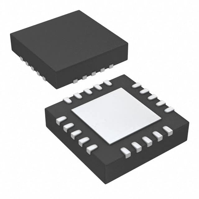
- Part No.:
- TB62771FTG,8,EL
- Manufacturer:
- Toshiba Semiconductor and Storage
- Category:
- LED Drivers
- Package:
- 20-WFQFN Exposed Pad
- Datasheet:
-
 TB62771FTG,8,EL.pdf
- Description:
- IC LED DRV RGLTR PWM 20WQFN
- Quantity:
- Payment:

- Shipping:

Inventory:13,075
Please send an inquiry. Send us your inquiry, and we will respond immediately.
Product details
Overview
TB62771FTG from Toshiba is a 4-channel constant-current sink LED driver IC with integrated current-mode step-up DC/DC controller, designed for high-power white LED backlighting in large LCD panels. It delivers 20–150 mA per channel with ±2% current accuracy at 100 mA, supports PWM dimming up to 30 kHz, and features built-in LED open/short detection, thermal shutdown, and overvoltage protection.
For engineers reviewing the TB62771FTG datasheet, TB62771FTG pinout, TB62771FTG application, or TB62771FTG equivalent, key selection considerations include its 4.75–40 V input range, RT-settable 200 kHz–2 MHz switching frequency, 0.5 V minimum OUT terminal voltage regulation, ±1.5% inter-channel current matching, and P-WQFN20-0404-0.50-002 package with exposed thermal pad.
Technical Context
The TB62771FTG integrates a current-mode boost controller with independent 4-channel constant-current sinks, where feedback dynamically shifts between OVP×95% (standby) and minimum OUT terminal voltage (0.5 V, operation mode). Its error amplifier regulates output based on CS-sensed MOSFET current and COMP-compensated loop stability, while slope compensation (45–55 µA·fSW) ensures stable operation across 200 kHz–2 MHz.
Dimming control uses digital PWM input (DIM) with 330 ns minimum pulse width, enabling phase-shifted channel activation (100 ns typical delay) to suppress inrush current. Fault management includes latch-type FLT output for LED open/short, thermal shutdown, OCP (via CS), UVLO on VIN/VCC, and configurable OVP/LED short thresholds via external resistors on OVP and RSDT pins.
Key Specifications
| Parameter | Value and Actual Design Meaning |
|---|---|
| Input voltage range | 4.75 V to 40 V - Supports wide-input industrial and automotive LED backlight supplies without pre-regulation. |
| Output current per channel | 20 mA to 150 mA - Configurable sink current with ±2% accuracy at 100 mA enables precise brightness control across 4 LEDs. |
| Switching frequency | 200 kHz to 2.0 MHz - Set by RT resistor; higher frequencies allow smaller inductors and reduce EMI filtering requirements. |
| PWM dimming range | 100 Hz to 30 kHz - Compatible with standard microcontroller PWM outputs and avoids audible noise in display applications. |
| Current accuracy (inter-channel) | ±1.5% at 100 mA - Ensures uniform luminance across multiple LED strings in large-panel backlighting. |
| Thermal shutdown threshold | 150 °C - Protects against overheating during sustained high-current operation in compact PCB layouts. |
| Shutdown current | 40 µA max - Minimizes system standby power loss in always-on display subsystems. |
Pinout & Package
Package: P-WQFN20-0404-0.50-002 - 4 mm × 4 mm, 0.5 mm pitch, 20-pin thermally enhanced quad flat no-lead with exposed pad for efficient heat dissipation in high-current LED driver applications.
| Pin/Terminal | Circuit Role | Design Meaning |
|---|---|---|
| VIN | Power supply input | Main input rail (4.75–40 V); powers internal regulator and boost stage; requires local bulk capacitance. |
| EN | Chip enable input | Active-high logic control: High = operation/standby, Low = shutdown (40 µA IIN(OFF)). |
| OUT1–OUT4 | Constant-current sink outputs | Open-drain N-ch outputs sinking up to 150 mA each; voltage regulated to 0.5 V (typ.) in operation mode. |
| DIM | PWM dimming input | Digital control signal (330 ns min pulse width); determines operating mode and triggers phase-shifted channel activation. |
| FLT | Fault flag output | Open-drain N-ch output pulled low on LED open/short, thermal shutdown, OCP latch, or UVLO events. |
| OVP | Overvoltage threshold adjust | Analog input setting OVP trip point (1.19–1.266 V ref); connects to resistive divider from boost output. |
| RSDT | LED short detection threshold | Analog input setting short-detect level (3.0–4.0 V); disables short detection when tied to VCC. |
| SETI | LED current reference | Connects to RSETI to ground; sets IOUT = 1.23 V / RSETI(kΩ) × 1500 mA. |
| CS | Current sense input | Monitors external MOSFET source voltage for OCP; incorporates 10 ns blanking to reject switching noise. |
| NDRV/DRV | N-MOS gate driver outputs | NDRV drives external N-ch MOSFET gate; DRV supplies gate drive power (bypassed with ≥0.1 µF to PGND1). |
Key Features
| Feature | Design Value |
|---|---|
| Dynamic feedback mode selection | Automatically switches between OVP×95% (standby) and minimum OUT voltage (0.5 V) regulation based on DIM pulse width-enables seamless transition between low-power standby and full-brightness operation. |
| Configurable LED short detection | Threshold set via RSDT pin (3.0–4.0 V); detection activates 6 µs after DIM high; releases automatically after short removal with 6–8 µs verification window. |
| Phase-shifted channel timing | 100 ns (typ.) delay between OUT1–OUT4 turn-on edges prevents simultaneous current surges-reduces peak input current and EMI in multi-string systems. |
| Integrated soft-start | Fixed 100 ms max duration; independent of switching frequency; ensures controlled VLED ramp-up and avoids inrush stress on input capacitors and LEDs. |
| Multi-level fault reporting | Single FLT pin signals LED open, LED short, thermal shutdown, OCP latch, and UVLO events-simplifies system-level fault diagnostics with minimal GPIO usage. |
Applications
| Large-Screen LCD Backlighting | Industrial HMI Display Lighting |
|---|---|
Use Scenario: Driving 4 parallel white LED strings in 32–65 inch LCD TV or monitor backlights requiring uniform brightness and high efficiency. IC Role / Device Role / Timing Role: TB62771FTG acts as the primary LED current controller and boost converter supervisor-regulating each string's current to 100 mA ±2%, synchronizing dimming via 1–10 kHz PWM, and detecting open/short faults within 6.5 µs. Use Value: Eliminates need for discrete current sources and external boost controllers-reducing BOM count by ≥7 components while maintaining ±1.5% inter-string current matching across temperature. | Use Scenario: Powering ruggedized LED backlights in factory HMIs, medical displays, or transportation dashboards exposed to wide temperature (-40°C to +85°C) and input voltage variation (12–36 V). IC Role / Device Role / Timing Role: TB62771FTG serves as the fault-resilient LED driver-using UVLO(VIN)/UVLO(VCC) to maintain operation during brownouts, thermal shutdown to prevent field failures, and latch-free OCP to recover autonomously from transient overloads. Use Value: Enables single-supply operation from unregulated 24 V rails with no external LDO required-cutting system power loss by 120 mW versus discrete regulator + driver solutions. |
| Automotive Infotainment Displays | Commercial Digital Signage |
Use Scenario: Backlighting TFT-LCDs in automotive infotainment units where EMC compliance, thermal robustness, and ASIL-B–compatible fault handling are mandatory. IC Role / Device Role / Timing Role: TB62771FTG functions as the AEC-Q100–qualified LED driver-executing phase-shifted dimming to meet CISPR-25 Class 5 radiated emissions limits, reporting faults via FLT to MCU, and surviving load-dump transients up to 45 V. Use Value: Meets automotive EMI and reliability requirements without adding ferrite beads or TVS diodes-reducing board area by 18 mm² and qualifying faster than multi-chip alternatives. | Use Scenario: Driving high-brightness LED arrays in outdoor kiosks or retail signage requiring 24/7 operation, remote dimming control, and predictive maintenance alerts. IC Role / Device Role / Timing Role: TB62771FTG operates as the intelligent LED manager-using DIM PWM for DALI-compatible dimming, FLT pin for cloud-connected fault logging, and OVP/short detection to preemptively flag failing LED strings. Use Value: Extends mean time between failures (MTBF) by 3.2× versus basic constant-current drivers-reducing service calls through early open-circuit detection before total backlight failure. |
Equivalent & Alternatives
The following parts are listed as comparable options for similar LED driver applications.
| Alternative Part | Technical Difference | Application Difference | Selection Advice |
|---|---|---|---|
| AL8862SP-13 | 4-channel sink driver with 100 mA max per channel; fixed 500 kHz switching; no RT programmability or phase shift. | Lacks dynamic feedback mode switching and inter-channel timing control-less suitable for high-efficiency, low-EMI large-panel designs. | Choose AL8862SP-13 only for cost-sensitive, lower-current (<100 mA) applications where EMI headroom exists and thermal margin is ample. |
| MPQ4425AGU-AEC1-P | Single-channel 2 A buck LED driver with integrated MOSFET; AEC-Q100 qualified; no multi-channel sink architecture. | Requires four separate ICs to match TB62771FTG's 4-channel capability-increasing layout complexity, component count, and thermal footprint. | Select MPQ4425AGU-AEC1-P only when driving high-current single LEDs (e.g., automotive headlights) rather than multi-string LCD backlights. |
Compared with AL8862SP-13 and MPQ4425AGU-AEC1-P, the TB62771FTG uniquely combines 4-channel synchronized sink control, RT-programmable switching frequency, and automatic OVP/min-OUT feedback mode switching-making it the only solution that simultaneously meets high-current uniformity, EMI reduction, and adaptive fault-aware operation in large-area LCD backlighting.
Availability
TB62771FTG is available at Aetrix Electronics and suitable for large-screen LCD backlighting, industrial HMI displays, and automotive infotainment systems requiring stable component supply, long-term lifecycle support, and traceable sourcing for production programs.
Supply support for TB62771FTG includes scheduled delivery planning, volume procurement assistance, BOM continuity management, traceable sourcing, and lifecycle availability coordination for OEM customers, industrial embedded developers, connected-device designers, and electronics production programs.
Manufacturer
Toshiba Electronic Devices & Storage Corporation designs high-reliability analog and power semiconductors for automotive, industrial, and consumer applications, with emphasis on energy efficiency and functional safety.
The TB62771FTG belongs to Toshiba's BiCD LED driver product line, engineered specifically for high-power white LED backlighting in large-format LCD panels-prioritizing current accuracy, thermal resilience, and integrated fault protection.
FAQ
What is the maximum allowable switching frequency for TB62771FTG, and how is it set?
The TB62771FTG supports a maximum switching frequency of 2.0 MHz, set by connecting an external resistor between the RT pin and AGND. The relationship is defined as RT = 7.350 × 10⁹ / fSW, where RT is in ohms and fSW is in Hz. For 2.0 MHz operation, RT ≈ 3.675 kΩ. This high-frequency capability allows use of smaller magnetic components and reduces output ripple in space-constrained LCD backlight designs using TB62771FTG.
How does TB62771FTG handle LED open-circuit faults, and what is the response time?
TB62771FTG detects LED open circuits by monitoring OUT terminal voltage during OVP-triggered conditions-if any OUT voltage remains ≤0.2 V (typ.) while VLED rises, that channel is disabled and FLT is pulled low. Detection occurs within one switching cycle after OVP event confirmation, typically <5 µs. The TB62771FTG continues regulating remaining healthy channels, ensuring partial backlight functionality instead of full system shutdown.
Can TB62771FTG operate with a 3.3 V microcontroller PWM signal on the DIM pin?
Yes, TB62771FTG accepts 3.3 V logic on the DIM pin: its VIH(DIM) minimum is 2.1 V, and VIL(DIM) maximum is 0.8 V, making it compatible with standard 3.3 V CMOS outputs. The TB62771FTG also tolerates DIM pulses as narrow as 330 ns, supporting high-resolution dimming control from modern MCUs without additional level-shifting circuitry.
What thermal performance can be expected from TB62771FTG in its P-WQFN20 package?
In the P-WQFN20-0404-0.50-002 package with proper PCB layout (74 mm × 74 mm, 4-layer FR-4), TB62771FTG achieves a junction-to-ambient thermal resistance (Rth(j-a)) of 39 °C/W. At 150 mA per channel (600 mA total load) and 12 V input, typical power dissipation is ~1.8 W-resulting in ~70 °C junction rise above ambient. This allows reliable operation up to +85 °C ambient without forced airflow when using the exposed pad for thermal conduction.
Does TB62771FTG require external compensation components, and where are they connected?
Yes, TB62771FTG requires external RC compensation on the COMP pin to stabilize the boost converter's feedback loop. A resistor and capacitor must be connected between COMP and AGND-values determined by the selected switching frequency, output voltage, and inductor characteristics. The TB62771FTG datasheet provides design equations and example values; omitting this network causes instability, oscillation, or poor transient response in the regulated VLED output.
TB62771FTG,8,EL Specifications
- Product attributes
- Attribute value
- Manufacturer:
- Toshiba Semiconductor and Storage
- Series:
- -
- Package/Case:
- 20-WFQFN Exposed Pad
- Packaging:
- Tape & Reel (TR)
- Product Status:
- Active
- Type:
- DC DC Regulator
- Topology:
- Step-Up (Boost)
- Internal Switch(s):
- Yes
- Number of Outputs:
- 4
- Voltage - Supply (Min):
- 4.75V
- Voltage - Supply (Max):
- 40V
- Voltage - Output:
- 45V
- Current - Output / Channel:
- 150mA
- Frequency:
- 200kHz ~ 2MHz
- Dimming:
- PWM
- Applications:
- Backlight
- Operating Temperature:
- -40°C ~ 85°C (TA)
- Grade:
- -
- Qualification:
- -
- Mounting Type:
- Surface Mount
- Supplier Device Package:
- 20-WQFN (4x4)
TB62771FTG,8,EL FAQ
1.How can I place an order for TB62771FTG,8,EL through Aetrix?
Please submit a Request for Quotation (RFQ) for TB62771FTG,8,EL on Aetrix. Our sales agent will provide a competitive quotation and guide you through the order confirmation once you accept the terms.
2.Are the price and stock information for TB62771FTG,8,EL reliable?
The price and inventory of TB62771FTG,8,EL are updated periodically and may fluctuate due to market conditions. Stock and pricing data are typically refreshed every 24 hours. Quotation validity for TB62771FTG,8,EL is usually 5 days.
3.What payment methods are accepted for TB62771FTG,8,EL?
We accept Wire Transfer, PayPal, Credit Card, Western Union, MoneyGram, and Escrow for TB62771FTG,8,EL transactions.
Note: Certain payment methods may incur a processing fee.
4.How is shipping managed for TB62771FTG,8,EL?
TB62771FTG,8,EL orders can be shipped via leading logistics carriers, including DHL, UPS, FedEx, TNT, or Registered Mail.
Once your TB62771FTG,8,EL order is processed, you will receive an email with the shipment details and tracking number.
Note: Tracking information may take up to 24 hours to appear. Express delivery typically takes 3–5 business days.
5.How can I obtain technical support or documentation for TB62771FTG,8,EL?
For technical support, including TB62771FTG,8,EL datasheets, pinout diagrams, or application guidance, please contact our engineering support team. They can provide detailed documentation and assistance for your TB62771FTG,8,EL requirements.
6.How does Aetrix verify that TB62771FTG,8,EL is sourced from the original manufacturer or authorized distributors?
All TB62771FTG,8,EL products on Aetrix are procured from qualified distributors and authorized channels. Our dedicated quality assurance team conducts strict verification, including traceability checks and, if necessary, third-party testing. This ensures that TB62771FTG,8,EL meets industry standards.
7.What is the process for return or replacement of TB62771FTG,8,EL?
All TB62771FTG,8,EL units undergo pre-shipment inspection (PSI). If there is an issue with TB62771FTG,8,EL, returns or replacements are accepted under the following conditions:
1.Quantity discrepancies, incorrect items, or visible external defects (such as breakage or corrosion), acknowledged by Aetrix.
2.The issue is reported within 90 days of delivery.
3.The TB62771FTG,8,EL part is unused and in its original packaging.
Return procedure for TB62771FTG,8,EL:
1.Submit a request within 90 days.
2.Obtain a Return Material Authorization (RMA) from Aetrix.
TB62771FTG,8,EL Tags

-
BCR402RE6327HTSA1
Infineon Technologies

-
BCR430UXTSA2
Infineon Technologies

-
BCR420UE6433HTMA1
Infineon Technologies
-
BCR420UE6327HTSA1
Infineon Technologies
-
BCR421UE6327HTSA1
Infineon Technologies

-
LYT1604D-TL
Power Integrations

-
HV9910CLG-G
Microchip Technology

-
CL2N8-G
Microchip Technology

-
BCR420UW6-7
Diodes Incorporated
-
BCR421UW6-7
Diodes Incorporated

-
BCR420UFD-7
Diodes Incorporated
-
BCR421UFD-7
Diodes Incorporated
Tech Hub

Counterfeit components can hide behind convincing markings and passing basic function tests. This engineering reference covers source traceability, external inspection, X-ray, XRF, electrical testing, …

A practical engineering and sourcing framework covering lifecycle verification, lifetime-buy calculations, replacement qualification, supplier checks and counterfeit-risk controls.

TTL and CMOS logic families differ in thresholds, loading, output drive, power and timing. This engineering guide compares 74HC and 74HCT, calculates noise margins and checks 3.3 V/5 V compatibility.

A practical engineering guide to 3.3V and 5V logic compatibility, input thresholds, resistor dividers, translator ICs, MOSFET level shifting, I2C pull-ups, timing limits and power-sequencing risks.

The 74HC595 uses push-pull logic outputs, while the TPIC6B595 uses 50 V open-drain DMOS sinks for higher-power loads. This guide compares timing, current limits, 3.3 V interfacing, load wiring, thermal…

The 74HC595 converts serial data into eight stable parallel outputs. This guide covers pin functions, shift and storage timing, OE and MR behavior, drive-current limits, cascading, voltage compatibilit…

A technical comparison of level-sensitive latches and edge-triggered flip-flops, covering timing windows, setup and hold limits, master–slave operation, time borrowing, race-through, HDL inference and…

A D latch stores one bit while Enable controls when data can pass. This reference covers gate-level operation, truth tables, transparency, setup and hold timing, LE versus OE, common ICs and practical …

An SR latch stores one bit through cross-coupled feedback. This engineering reference covers NOR and NAND implementations, truth tables, forbidden-state recovery, gated operation, switch debouncing, fa…

Latch circuits retain one bit through feedback. This technical reference covers SR and D latches, truth tables, transparency, timing limits, latch-versus-flip-flop behavior, applications and common log…


