
 My Inquiry
 My Account


Toshiba Semiconductor and Storage TBD62781AFWG,EL
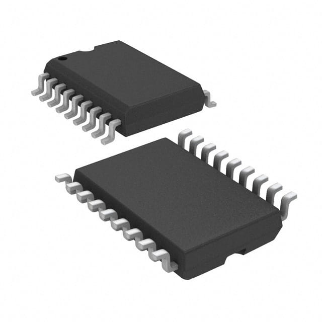
- Part No.:
- TBD62781AFWG,EL
- Manufacturer:
- Toshiba Semiconductor and Storage
- Package:
- 18-SOIC (0.295", 7.50mm Width)
- Datasheet:
-
 TBD62781AFWG,EL.pdf
- Description:
- TRANSISTOR ARRAY INTERFACE DRIVE
- Quantity:
- Payment:

- Shipping:

Inventory:2,217
Please send an inquiry. Send us your inquiry, and we will respond immediately.
Product details
Overview
TBD62781AFWG,EL from Toshiba Electronic Devices & Storage Corporation is an 8-channel source-type DMOS transistor array IC designed for high-voltage, medium-current switching in industrial and automotive control systems. It delivers up to 50 V output voltage, −400 mA per channel (at 25°C), and features built-in pull-down resistors at outputs. Its P-SOP18 package supports compact PCB layouts in relay drivers, LED matrix controllers, and solenoid interface circuits.
For engineers reviewing the TBD62781AFWG,EL datasheet, TBD62781AFWG,EL pinout, TBD62781AFWG,EL application, or TBD62781AFWG,EL equivalent, key selection criteria include per-channel current capability under thermal derating, input logic threshold compatibility with 3.3 V/5 V microcontrollers, output ON-resistance at rated load, and thermal dissipation limits on standard FR-4 PCBs.
Technical Context
The TBD62781AFWG,EL integrates eight independent N-channel DMOS transistors in a single monolithic BiCD silicon die, each with a dedicated input and open-drain source-output configuration. Each channel includes a built-in pull-down resistor to ensure defined low-state behavior when inactive.
It operates with a wide VCC range (−0.5 V to 50 V), accepts TTL/CMOS-compatible inputs (VIN(ON) ≥ 2.0 V, VIN(OFF) ≤ 0.6 V), and exhibits fast switching (tON = 0.4 μs, tOFF = 2.0 μs) under 50 V supply and 125 Ω load conditions. No internal overcurrent or overvoltage protection is included - external fusing and layout-level fault mitigation are mandatory.
Key Specifications
| Parameter | Value and Actual Design Meaning |
|---|---|
| Output Voltage Max | 50 V - supports direct driving of 24 V industrial loads and 36 V solenoids without external level-shifting |
| Output Current Max (per ch) | −400 mA @ 25°C - sufficient for driving small relays (e.g., 12 V/400 mA coil) or multiplexed LED segments |
| Input Threshold (ON) | 2.0 V min - compatible with 3.3 V GPIOs and standard 5 V logic without Schmitt-trigger buffering |
| Input Threshold (OFF) | 0.6 V max - ensures reliable turn-off even with noise margin or weak pull-downs |
| ON-Resistance (Typ) | 0.56 V @ −350 mA - yields <195 mΩ RDS(on), minimizing power loss and self-heating at full load |
| Power Dissipation (FWG) | 1.31 W @ 25°C on 75×114 mm PCB - requires thermal pad or copper pour for >300 mA continuous operation |
| Switching Speed | tON = 0.4 μs, tOFF = 2.0 μs - enables PWM dimming up to ~200 kHz with minimal dead-time distortion |
Pinout & Package
P-SOP18-0812-1.27-001 surface-mount package: 18-pin, 1.27 mm pitch, 11.0 × 7.0 × 2.05 mm body, 0.48 g typical weight. Exposed thermal pad recommended for heatsinking.
| Pin/Terminal | Circuit Role | Design Meaning |
|---|---|---|
| 1–8 (I1–I8) | Digital input control | Active-high logic inputs; drive each DMOS channel independently; no internal pull-up required |
| 9 (GND) | Ground reference | Common return for all channels and logic; must be low-impedance path to minimize ground bounce |
| 10 (VCC) | High-side power rail | Supplies all 8 output channels; decoupling capacitor (≥10 μF) required near pin 10 |
| 11–18 (O8–O1) | Source-type open-drain outputs | Each connects to load cathode (LED) or low-side of relay coil; sinks current to GND when active |
Key Features
| Feature | Design Value |
|---|---|
| 8-channel integration | Reduces component count vs. discrete MOSFETs; eliminates 8x gate-drive routing and layout complexity |
| Built-in pull-down resistors | Ensures defined OFF-state without external resistors - critical for fail-safe relay de-energization |
| 50 V output rating | Supports 24 V DC industrial buses and legacy 36 V automotive subsystems without external clamping |
| Low input current (≤0.1 mA) | Minimizes loading on MCU GPIOs; allows direct connection to low-drive-strength microcontrollers |
| Thermal derating curve | 10.48 mW/°C reduction above 25°C - enables accurate junction temperature estimation for long-term reliability |
Applications
| Industrial Relay Driver | Automotive Body Control Module |
|---|---|
Use Scenario: Driving 8 independent 24 VDC electromagnetic relays in PLC I/O modules or HVAC control panels. IC Role / Device Role / Timing Role: High-side switch controller with integrated logic-level translation and sink-current capability. Use Value: Eliminates need for 8 discrete driver transistors and base resistors; simplifies BOM and reduces board area by >40%. |
Use Scenario: Controlling door lock actuators, mirror heaters, and interior lighting in vehicle body electronics. IC Role / Device Role / Timing Role: Load-switching interface between 3.3 V CAN/LIN microcontroller and 12 V automotive loads. Use Value: Tolerates battery transients up to 50 V; input thresholds match automotive-grade MCUs without level shifters. |
| LED Matrix Display Driver | Printer Head Solenoid Controller |
Use Scenario: Row/column scanning of 8×8 red/green LED matrices in signage or instrumentation displays. IC Role / Device Role / Timing Role: Column-sink driver enabling multiplexed current control with precise timing. Use Value: Fast 0.4 μs turn-on supports high refresh rates (>1 kHz) without visible flicker or ghosting. |
Use Scenario: Sequenced actuation of print head solenoids in dot-matrix or impact printers. IC Role / Device Role / Timing Role: Precision current sink for inductive pulse loads requiring controlled rise/fall times. Use Value: Built-in pull-down prevents unintended solenoid chatter during microcontroller reset or brown-out. |
Equivalent & Alternatives
The following parts are listed as comparable options for similar high-voltage DMOS array applications.
| Alternative Part | Technical Difference | Application Difference | Selection Advice |
|---|---|---|---|
| TBD62783AFWG,EL | 8-channel sink-type array with identical package and pinout; higher RDS(on) (0.85 V @ −350 mA) | Same relay/LED use cases but lower efficiency at high current; reduced thermal margin | Select when cost sensitivity outweighs thermal performance; verify junction temp rise under worst-case duty cycle |
| ULN2803ADWR | Bipolar Darlington array (not DMOS); 500 mA per channel but higher VCE(sat) (1.3 V), slower switching (tOFF ≈ 250 μs) | Suitable for static relay driving but unsuitable for PWM-based LED dimming or fast solenoid sequencing | Prefer for legacy designs where bipolar saturation voltage is acceptable and speed is not critical |
Compared with TBD62781AFWG,EL, TBD62783AFWG,EL offers identical form factor but trades lower conduction loss for higher thermal resistance, while ULN2803ADWR provides proven robustness in non-PWM applications at the expense of efficiency and bandwidth.
Availability
TBD62781AFWG,EL is available at Aetrix Electronics and suitable for industrial automation, automotive body electronics, and printer peripheral design requiring stable component supply and long-lifecycle support.
Supply support for TBD62781AFWG,EL includes scheduled delivery planning, volume procurement assistance, BOM continuity management, traceable sourcing, and lifecycle availability coordination for OEM customers, industrial embedded developers, connected-device designers, and electronics production programs.
Manufacturer
Toshiba Electronic Devices & Storage Corporation is a Japanese semiconductor manufacturer specializing in power devices, logic ICs, and storage solutions with over 50 years of analog and mixed-signal design heritage.
The TBD62781AFWG,EL belongs to Toshiba's BiCD DMOS transistor array product line, engineered for high-reliability industrial switching where voltage tolerance, channel density, and thermal predictability are prioritized over ultra-low quiescent current.
FAQ
What is the maximum continuous output current per channel for TBD62781AFWG,EL at 85°C ambient?
The TBD62781AFWG,EL supports −370 mA per channel at Ta = 85°C with 10% duty cycle and Tj = 120°C (P-SOP18 package on specified PCB). This derated value accounts for thermal resistance and ensures safe junction temperature. For continuous DC operation at 85°C, limit current to ≤−160 mA per channel per datasheet Table 3. Always verify actual board-level thermal performance using IR imaging or thermocouple measurement.
Does TBD62781AFWG,EL include internal ESD or overvoltage protection?
No, the TBD62781AFWG,EL does not incorporate internal ESD protection diodes, overvoltage clamps, or overcurrent limiting circuitry. The absolute maximum ratings define hard limits - exceeding VCC > 50 V or IOUT > −500 mA risks immediate failure. System-level protection (TVS diodes on VCC, series resistors on inputs, fuse on VCC rail) is mandatory per Toshiba's usage precautions.
Can TBD62781AFWG,EL drive inductive loads like relays or solenoids directly?
Yes, the TBD62781AFWG,EL is qualified for inductive load switching, but external flyback diodes must be placed across each load (cathode to VCC, anode to output pin) to suppress back-EMF. Toshiba explicitly warns that unclamped inductive kick can exceed VCC rating and destroy the DMOS channel. Layout must minimize loop inductance between output pin, diode, and load.
Is the TBD62781AFWG,EL pin-compatible with the through-hole TBD62781APG variant?
No, the TBD62781AFWG,EL (P-SOP18) and TBD62781APG (P-DIP18) share identical pin functions and numbering but differ in physical package, pitch (1.27 mm vs. 2.54 mm), and thermal characteristics. They are functionally equivalent but not mechanically interchangeable - PCB redesign is required to swap between them.
What is the recommended minimum input voltage to guarantee reliable turn-on of TBD62781AFWG,EL?
The TBD62781AFWG,EL guarantees turn-on when VIN ≥ 2.0 V (min) under test condition IOUT ≥ −100 mA and VDS = 2.0 V. For robust operation across voltage and temperature variation, design with VIN ≥ 2.5 V. Input current remains ≤0.1 mA, so standard MCU GPIOs can drive it directly without buffer stages.
TBD62781AFWG,EL Specifications
- Product attributes
- Attribute value
- Manufacturer:
- Toshiba Semiconductor and Storage
- Package/Case:
- 18-SOIC (0.295", 7.50mm Width)
- Series:
- -
- Packaging:
- Tape & Reel (TR)
- Product Status:
- Active
- Switch Type:
- General Purpose
- Number of Outputs:
- 8
- Ratio - Input:Output:
- 1:1
- Output Configuration:
- High Side
- Output Type:
- P-Channel
- Interface:
- On/Off
- Voltage - Load:
- 50V (Max)
- Voltage - Supply (Vcc/Vdd):
- Not Required
- Current - Output (Max):
- 400mA
- Rds On (Typ):
- 1.6Ohm
- Input Type:
- Non-Inverting
- Features:
- -
- Fault Protection:
- -
- Operating Temperature:
- -40°C ~ 85°C
- Grade:
- -
- Qualification:
- -
- Mounting Type:
- Surface Mount
- Supplier Device Package:
- 18-SOP
TBD62781AFWG,EL FAQ
1.How can I place an order for TBD62781AFWG,EL through Aetrix?
Please submit a Request for Quotation (RFQ) for TBD62781AFWG,EL on Aetrix. Our sales agent will provide a competitive quotation and guide you through the order confirmation once you accept the terms.
2.Are the price and stock information for TBD62781AFWG,EL reliable?
The price and inventory of TBD62781AFWG,EL are updated periodically and may fluctuate due to market conditions. Stock and pricing data are typically refreshed every 24 hours. Quotation validity for TBD62781AFWG,EL is usually 5 days.
3.What payment methods are accepted for TBD62781AFWG,EL?
We accept Wire Transfer, PayPal, Credit Card, Western Union, MoneyGram, and Escrow for TBD62781AFWG,EL transactions.
Note: Certain payment methods may incur a processing fee.
4.How is shipping managed for TBD62781AFWG,EL?
TBD62781AFWG,EL orders can be shipped via leading logistics carriers, including DHL, UPS, FedEx, TNT, or Registered Mail.
Once your TBD62781AFWG,EL order is processed, you will receive an email with the shipment details and tracking number.
Note: Tracking information may take up to 24 hours to appear. Express delivery typically takes 3–5 business days.
5.How can I obtain technical support or documentation for TBD62781AFWG,EL?
For technical support, including TBD62781AFWG,EL datasheets, pinout diagrams, or application guidance, please contact our engineering support team. They can provide detailed documentation and assistance for your TBD62781AFWG,EL requirements.
6.How does Aetrix verify that TBD62781AFWG,EL is sourced from the original manufacturer or authorized distributors?
All TBD62781AFWG,EL products on Aetrix are procured from qualified distributors and authorized channels. Our dedicated quality assurance team conducts strict verification, including traceability checks and, if necessary, third-party testing. This ensures that TBD62781AFWG,EL meets industry standards.
7.What is the process for return or replacement of TBD62781AFWG,EL?
All TBD62781AFWG,EL units undergo pre-shipment inspection (PSI). If there is an issue with TBD62781AFWG,EL, returns or replacements are accepted under the following conditions:
1.Quantity discrepancies, incorrect items, or visible external defects (such as breakage or corrosion), acknowledged by Aetrix.
2.The issue is reported within 90 days of delivery.
3.The TBD62781AFWG,EL part is unused and in its original packaging.
Return procedure for TBD62781AFWG,EL:
1.Submit a request within 90 days.
2.Obtain a Return Material Authorization (RMA) from Aetrix.
TBD62781AFWG,EL Tags

-
TPS22919DCKR
Texas Instruments

-
MIC2091-1YM5-TR
Microchip Technology

-
MIC2090-1YM5-TR
Microchip Technology

-
TPS22995RZFR
Texas Instruments

-
TPS22975DSGR
Texas Instruments

-
SIP32510DT-T1-GE3
Vishay Siliconix

-
ULN2003D1013TR
STMicroelectronics

-
MIC2005A-1YM5-TR
Microchip Technology

-
MIC2005A-1YM6-TR
Microchip Technology

-
TPS22916BYFPR
Texas Instruments

-
TPS22917DBVR
Texas Instruments

-
ULN2003APWR
Texas Instruments
Tech Hub

Counterfeit components can hide behind convincing markings and passing basic function tests. This engineering reference covers source traceability, external inspection, X-ray, XRF, electrical testing, …

A practical engineering and sourcing framework covering lifecycle verification, lifetime-buy calculations, replacement qualification, supplier checks and counterfeit-risk controls.

TTL and CMOS logic families differ in thresholds, loading, output drive, power and timing. This engineering guide compares 74HC and 74HCT, calculates noise margins and checks 3.3 V/5 V compatibility.

A practical engineering guide to 3.3V and 5V logic compatibility, input thresholds, resistor dividers, translator ICs, MOSFET level shifting, I2C pull-ups, timing limits and power-sequencing risks.

The 74HC595 uses push-pull logic outputs, while the TPIC6B595 uses 50 V open-drain DMOS sinks for higher-power loads. This guide compares timing, current limits, 3.3 V interfacing, load wiring, thermal…

The 74HC595 converts serial data into eight stable parallel outputs. This guide covers pin functions, shift and storage timing, OE and MR behavior, drive-current limits, cascading, voltage compatibilit…

A technical comparison of level-sensitive latches and edge-triggered flip-flops, covering timing windows, setup and hold limits, master–slave operation, time borrowing, race-through, HDL inference and…

A D latch stores one bit while Enable controls when data can pass. This reference covers gate-level operation, truth tables, transparency, setup and hold timing, LE versus OE, common ICs and practical …

An SR latch stores one bit through cross-coupled feedback. This engineering reference covers NOR and NAND implementations, truth tables, forbidden-state recovery, gated operation, switch debouncing, fa…

Latch circuits retain one bit through feedback. This technical reference covers SR and D latches, truth tables, transparency, timing limits, latch-versus-flip-flop behavior, applications and common log…


