
 My Inquiry
 My Account


Microchip Technology TC7109ACPL
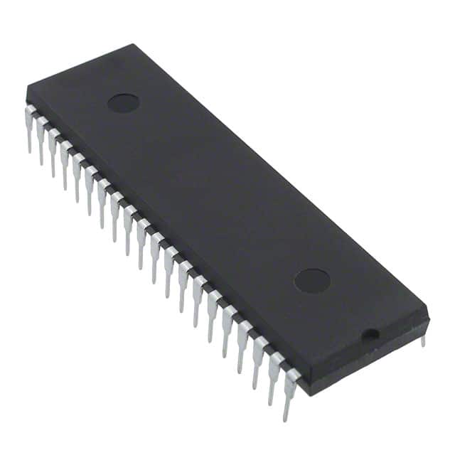
- Part No.:
- TC7109ACPL
- Manufacturer:
- Microchip Technology
- Category:
- Analog to Digital Converters (ADC)
- Package:
- 40-DIP (0.600", 15.24mm)
- Datasheet:
-
 TC7109ACPL.pdf
- Description:
- IC ADC 12BIT DUAL SLOPE 40DIP
- Quantity:
- Payment:

- Shipping:

Inventory:2,133
Please send an inquiry. Send us your inquiry, and we will respond immediately.
Product details
Overview
TC7109ACPL from Microchip Technology is a 12-bit plus sign, dual-slope integrating analog-to-digital converter (ADC) with true differential input and reference, 15 µVP-P typical input noise, 1 pA typical input bias current, and zero integrator cycle for fast overload recovery. It operates with ±5 V supplies and is used in precision bridge-based sensor interfaces such as load cells and strain gauges.
For engineers reviewing the TC7109ACPL datasheet, TC7109ACPL pinout, TC7109ACPL application, or TC7109ACPL equivalent, this page delivers verified specifications, validated 40-pin PDIP package mapping, confirmed dual-slope timing behavior, UART handshake mode support, and real-world design implications for data acquisition systems requiring high CMRR and auto-zero stability.
Technical Context
The TC7109ACPL implements a four-phase dual-slope conversion cycle: Auto-Zero (AZ), Signal Integrate (INT), Reference De-integrate (DE), and Zero Integrator (ZI). Its AZ phase achieves <10 µV input-referred offset via closed-loop compensation of buffer, integrator, and comparator offsets.
It supports two digital interface modes: Direct mode (TTL-compatible parallel byte access via CE/LOAD, HBEN, LBEN) and Handshake mode (UART-synchronized serial output using SEND, HBEN, LBEN, and CE/LOAD as outputs). The RUN/HOLD input enables controlled conversion start/stop and de-integrate truncation.
Key Specifications
| Parameter | Value and Actual Design Meaning |
|---|---|
| Resolution | 12-bit plus sign (±4095 counts), sign-magnitude coding format - enables direct signed decimal interpretation without software two's complement conversion. |
| Input Noise | 15 µVP-P typical - ensures stable readings below 1 LSB for 409.6 mV full-scale inputs (1 LSB = 100 µV). |
| Input Bias Current | 1 pA typical - eliminates significant voltage drop across high-impedance transducer sources like thermocouples or piezoresistive sensors. |
| Common-Mode Rejection | 50 µV/V (≈86 dB) - maintains accuracy when input signals float within V−+1.5 V to V++1.5 V, critical for ungrounded bridge measurements. |
| Overload Recovery | Zero integrator cycle (ZI phase) - clears residual integrator charge after overrange, preventing cross-talk errors in multiplexed channel systems. |
| Reference Output | −2.8 V (typ.) referenced to V+, with 80 ppm/°C tempco - provides stable internal reference for ratiometric measurements without external voltage references. |
| Supply Current | 700–1500 µA (V+ to V−) - enables low-power operation in battery-backed data loggers and portable instrumentation. |
Pinout & Package
TC7109ACPL is housed in a 40-pin plastic dual in-line package (PDIP), RoHS-compliant, rated for 0°C to +70°C operation. Pin spacing is 0.1 inch (2.54 mm), body width 0.6 inches (15.24 mm), suitable for through-hole prototyping and industrial PCBs.
| Pin/Terminal | Circuit Role | Design Meaning |
|---|---|---|
| GND (Pin 1) | Digital ground reference | Return path for all digital logic; must be isolated from analog ground to prevent noise coupling into integrator node. |
| STATUS (Pin 2) | Conversion status flag | High during INT/DE phases; goes low ½ clock after latching - serves as hardware "data valid" interrupt trigger. |
| POL (Pin 3) | Polarity indicator | High = positive input voltage relative to COMMON; used with OR to determine signed result without decoding B12. |
| OR (Pin 4) | Over-range flag | Three-state output asserted high when |VIN| > full scale - enables automatic range switching or alarm signaling. |
| B1–B12 (Pins 5–16) | Data bus outputs | TTL-compatible, tri-state, byte-organized - B1–B8 (low byte), B9–B12 + POL + OR (high byte); require CE/LOAD and HBEN/LBEN control. |
| MODE (Pin 21) | Interface mode select | LOW = Direct parallel mode; HIGH = UART Handshake mode - configures CE/LOAD, HBEN, LBEN as outputs for UART sync. |
| RUN/HOLD (Pin 26) | Conversion timing control | High = continuous conversion; LOW = halt after zero crossing - allows precise synchronization with external controllers or power-saving duty cycling. |
| IN HI / IN LO (Pins 35/34) | Differential analog input | Accepts true differential signal referenced to COMMON (Pin 33); rejects common-mode noise up to 86 dB. |
| REF IN+ / REF IN− (Pins 36/39) | Differential reference input | Enables ratiometric measurement against external reference; minimizes rollover error when REF CAP+ and REF CAP− are properly decoupled. |
| V+ / V− (Pins 40/28) | Analog supply rails | +5 V and −5 V nominal - sets ±4 V integrator swing range; V− must be ≤ −5 V to avoid exceeding absolute max rating of −9 V. |
Key Features
| Feature | Design Value |
|---|---|
| Zero integrator cycle (ZI) | Eliminates hysteresis between successive conversions in multiplexed systems - prevents error propagation from overrange on one channel to next. |
| True differential input & reference | Supports bridge transducers (e.g., load cells) without external instrumentation amplifiers - reduces component count and board space. |
| Auto-zero architecture | Compensates for drift <1 µV/°C and input offset <10 µV - enables stable 12-bit accuracy over temperature without manual calibration. |
| UART handshake mode | Direct interface to HD6403/CDP1854 UARTs using SEND, HBEN, LBEN, CE/LOAD as outputs - removes need for glue logic in remote data loggers. |
| No zero adjustment required | Factory-trimmed auto-zero capacitor (CAZ) and integrator (CINT) eliminate potentiometer-based nulling - improves long-term reliability and reduces assembly time. |
Applications
| Industrial Weigh Scales | Thermocouple Data Acquisition |
|---|---|
Use Scenario: High-accuracy weight measurement in platform scales using 350 Ω strain gauge bridges with excitation derived from V+. IC Role / Device Role / Timing Role: Dual-slope ADC performing ratiometric conversion with internal 2.8 V reference; integrates for 2048 clocks, de-integrates until zero crossing. Use Value: 12-bit resolution + auto-zero drift <1 µV/°C enables ±0.01% FS repeatability across 0–50°C ambient without recalibration. |
Use Scenario: Cold-junction compensated thermocouple reading in HVAC controllers, where unused channels float to V+. IC Role / Device Role / Timing Role: ADC with zero integrator (ZI) phase suppresses cross-talk from overranged open thermocouple leads tied to V+. Use Value: ZI phase clears residual integrator charge in <1024 clocks - prevents false readings on subsequent active channels. |
| Portable Digital Multimeters | Bridge-Based Pressure Transducers |
Use Scenario: Battery-powered DMM measuring DC voltage, resistance, and continuity with autoranging. IC Role / Device Role / Timing Role: Low-power ADC (700 µA typical) with RUN/HOLD-controlled conversion bursts synchronized to button press. Use Value: RUN/HOLD halts de-integrate after zero crossing - reduces per-measurement time by up to 50%, extending battery life. |
Use Scenario: Medical infusion pump pressure monitoring using silicon piezoresistive bridge with 1–10 mV output. IC Role / Device Role / Timing Role: ADC with 1 pA input bias current avoids loading high-impedance bridge outputs; differential input rejects EMI from motor drivers. Use Value: 15 µVP-P noise floor resolves <0.1% FS pressure changes - meets IEC 60601-1 immunity requirements. |
Equivalent & Alternatives
The following parts are listed as comparable options for similar dual-slope ADC applications.
| Alternative Part | Technical Difference | Application Difference | Selection Advice |
|---|---|---|---|
| ICL7109CPL | 12-bit, same pinout, but no zero integrator cycle; higher input bias (10 pA typ.); no UART handshake mode. | Lacks ZI phase - unsuitable for multiplexed thermocouple systems with open inputs; requires external zero calibration. | Select only if cost sensitivity outweighs need for overload recovery and auto-zero stability. |
| MAX134ACPP | 18-bit sigma-delta ADC; SPI interface; 2.5 V supply; integrated PGA; no differential reference input. | Higher resolution but incompatible timing model; requires external reference and level-shifting for ±5 V bridge interfaces. | Choose for ultra-high-resolution static measurements where dual-slope speed is not required and system uses 3.3 V logic. |
Compared with ICL7109CPL and MAX134ACPP, the TC7109ACPL uniquely combines zero integrator recovery, true differential reference support, and UART handshake capability in a single 40-pin PDIP package - making it the only option for legacy-compatible, low-noise, multiplexed industrial sensor systems requiring minimal external components.
Availability
TC7109ACPL is available at Aetrix Electronics and suitable for industrial weigh scales, portable multimeters, thermocouple data loggers, and bridge-based pressure monitoring systems requiring stable component supply and long-term obsolescence management.
Supply support for TC7109ACPL includes scheduled delivery planning, volume procurement assistance, BOM continuity management, traceable sourcing, and lifecycle availability coordination for OEM customers, industrial embedded developers, connected-device designers, and electronics production programs.
Manufacturer
Microchip Technology is a U.S.-based semiconductor company specializing in microcontrollers, analog devices, and interface ICs, with emphasis on reliability, longevity, and industrial-grade qualification.
The TC7109ACPL belongs to Microchip's legacy precision analog converter family, designed specifically for high-stability, low-drift, dual-slope data acquisition in test equipment, instrumentation, and industrial control applications.
FAQ
What is the maximum recommended clock frequency for TC7109ACPL?
The TC7109ACPL requires exactly 8192 clock periods per full conversion cycle. While the datasheet specifies crystal or RC oscillator configurations, the maximum reliable clock frequency is 3.58 MHz - yielding a conversion rate of approximately 439 samples per second. Higher frequencies risk violating internal timing margins for auto-zero settling and integrator stability, especially under temperature variation. TC7109ACPL performance remains specified only up to this frequency.
Does TC7109ACPL support external reference voltage?
Yes, TC7109ACPL supports external reference via REF IN+ and REF IN− pins. When an external reference is applied, the internal 2.8 V REF OUT is disabled. The device maintains true differential reference operation, enabling ratiometric measurements against precision external sources such as LT1019 or REF5025. However, external reference must remain stable within ±0.1% over temperature to preserve 12-bit linearity - a requirement met by TC7109ACPL's own 80 ppm/°C internal reference.
How does the RUN/HOLD pin affect conversion timing in TC7109ACPL?
In TC7109ACPL, RUN/HOLD HIGH enables continuous conversion cycles; LOW forces early exit from de-integrate phase and entry into auto-zero hold state. When RUN/HOLD transitions HIGH after hold, STATUS goes HIGH 7 clock periods later, initiating the next integrate phase. This allows precise external synchronization - for example, triggering conversions only during low-noise windows in motor-driven systems. TC7109ACPL's internal pull-up ensures default continuous operation if pin is left floating.
Can TC7109ACPL be used with modern 3.3 V microcontrollers?
Yes, TC7109ACPL's TTL-compatible outputs (VOH = 3.5 V min at 700 µA) interface directly with 3.3 V logic inputs when pulled to 3.3 V via external resistors, provided VOL remains ≤0.4 V. However, its digital control inputs (MODE, HBEN, LBEN, CE/LOAD) require ≥2.5 V VIH and tolerate up to V+ (5 V), so level shifters are unnecessary for control signals. TC7109ACPL retains full functionality without logic-level translation - simplifying integration into mixed-voltage systems.
What is the purpose of the TEST pin on TC7109ACPL?
The TEST pin (Pin 17) on TC7109ACPL is a factory diagnostic input: when pulled LOW, it forces all B1–B12, POL, and OR outputs HIGH regardless of conversion result - verifying data bus integrity and latch functionality during production testing. In normal operation, TEST must be held HIGH (e.g., tied to V+) to ensure correct output behavior. Leaving TEST floating risks undefined outputs due to internal leakage paths, so TC7109ACPL designs must explicitly tie this pin to V+.
TC7109ACPL Specifications
- Product attributes
- Attribute value
- Manufacturer:
- Microchip Technology
- Series:
- -
- Package/Case:
- 40-DIP (0.600", 15.24mm)
- Packaging:
- Tube
- Product Status:
- Active
- Number of Bits:
- 12
- Sampling Rate (Per Second):
- 30
- Number of Inputs:
- 1
- Input Type:
- Differential
- Data Interface:
- Parallel
- Configuration:
- ADC
- Ratio - S/H:ADC:
- -
- Number of A/D Converters:
- 1
- Architecture:
- Dual Slope
- Reference Type:
- External
- Voltage - Supply, Analog:
- 5V
- Voltage - Supply, Digital:
- 5V
- Features:
- -
- Operating Temperature:
- 0°C ~ 70°C
- Supplier Device Package:
- 40-PDIP
- Mounting Type:
- Through Hole
- Grade:
- -
- Qualification:
- -
TC7109ACPL FAQ
1.How can I place an order for TC7109ACPL through Aetrix?
Please submit a Request for Quotation (RFQ) for TC7109ACPL on Aetrix. Our sales agent will provide a competitive quotation and guide you through the order confirmation once you accept the terms.
2.Are the price and stock information for TC7109ACPL reliable?
The price and inventory of TC7109ACPL are updated periodically and may fluctuate due to market conditions. Stock and pricing data are typically refreshed every 24 hours. Quotation validity for TC7109ACPL is usually 5 days.
3.What payment methods are accepted for TC7109ACPL?
We accept Wire Transfer, PayPal, Credit Card, Western Union, MoneyGram, and Escrow for TC7109ACPL transactions.
Note: Certain payment methods may incur a processing fee.
4.How is shipping managed for TC7109ACPL?
TC7109ACPL orders can be shipped via leading logistics carriers, including DHL, UPS, FedEx, TNT, or Registered Mail.
Once your TC7109ACPL order is processed, you will receive an email with the shipment details and tracking number.
Note: Tracking information may take up to 24 hours to appear. Express delivery typically takes 3–5 business days.
5.How can I obtain technical support or documentation for TC7109ACPL?
For technical support, including TC7109ACPL datasheets, pinout diagrams, or application guidance, please contact our engineering support team. They can provide detailed documentation and assistance for your TC7109ACPL requirements.
6.How does Aetrix verify that TC7109ACPL is sourced from the original manufacturer or authorized distributors?
All TC7109ACPL products on Aetrix are procured from qualified distributors and authorized channels. Our dedicated quality assurance team conducts strict verification, including traceability checks and, if necessary, third-party testing. This ensures that TC7109ACPL meets industry standards.
7.What is the process for return or replacement of TC7109ACPL?
All TC7109ACPL units undergo pre-shipment inspection (PSI). If there is an issue with TC7109ACPL, returns or replacements are accepted under the following conditions:
1.Quantity discrepancies, incorrect items, or visible external defects (such as breakage or corrosion), acknowledged by Aetrix.
2.The issue is reported within 90 days of delivery.
3.The TC7109ACPL part is unused and in its original packaging.
Return procedure for TC7109ACPL:
1.Submit a request within 90 days.
2.Obtain a Return Material Authorization (RMA) from Aetrix.
TC7109ACPL Tags
-
ADC081C021CIMKX/NOPB
Texas Instruments

-
MCP3021A5T-E/OT
Microchip Technology
-
TLA2024IRUGR
Texas Instruments
-
MCP3221A5T-E/OT
Microchip Technology
-
MCP3221A5T-I/OT
Microchip Technology
-
MCP3221A4T-E/OT
Microchip Technology
-
MCP3221A6T-E/OT
Microchip Technology
-
MCP3221A0T-E/OT
Microchip Technology
-
MCP3221A1T-E/OT
Microchip Technology

-
ADC121S021CIMFX/NOPB
Texas Instruments

-
MCP3001-I/MS
Microchip Technology

-
MCP3001-I/SN
Microchip Technology
Tech Hub

TTL and CMOS logic families differ in thresholds, loading, output drive, power and timing. This engineering guide compares 74HC and 74HCT, calculates noise margins and checks 3.3 V/5 V compatibility.

A practical engineering guide to 3.3V and 5V logic compatibility, input thresholds, resistor dividers, translator ICs, MOSFET level shifting, I2C pull-ups, timing limits and power-sequencing risks.

The 74HC595 uses push-pull logic outputs, while the TPIC6B595 uses 50 V open-drain DMOS sinks for higher-power loads. This guide compares timing, current limits, 3.3 V interfacing, load wiring, thermal…

The 74HC595 converts serial data into eight stable parallel outputs. This guide covers pin functions, shift and storage timing, OE and MR behavior, drive-current limits, cascading, voltage compatibilit…

A technical comparison of level-sensitive latches and edge-triggered flip-flops, covering timing windows, setup and hold limits, master–slave operation, time borrowing, race-through, HDL inference and…

A D latch stores one bit while Enable controls when data can pass. This reference covers gate-level operation, truth tables, transparency, setup and hold timing, LE versus OE, common ICs and practical …

An SR latch stores one bit through cross-coupled feedback. This engineering reference covers NOR and NAND implementations, truth tables, forbidden-state recovery, gated operation, switch debouncing, fa…

Latch circuits retain one bit through feedback. This technical reference covers SR and D latches, truth tables, transparency, timing limits, latch-versus-flip-flop behavior, applications and common log…

An engineering guide to LED driver operation, constant-current and constant-voltage outputs, linear and switching topologies, dimming, IC selection, calculations, replacement compatibility, and fault c…

Operational amplifier guide covering op amp basics, feedback, ideal vs real op amps, common configurations, buffer circuits, offset, bias current, gain-bandwidth, slew rate, rail-to-rail limits and sel…


