
 My Inquiry
 My Account


Microchip Technology TC7109CLW
- Part No.:
- TC7109CLW
- Manufacturer:
- Microchip Technology
- Category:
- Analog to Digital Converters (ADC)
- Package:
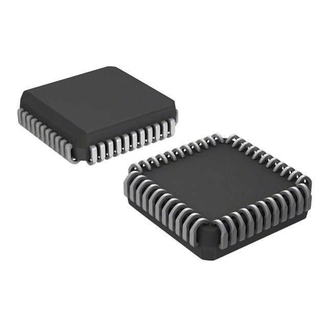
- 44-LCC (J-Lead)
- Datasheet:
-
 TC7109CLW.pdf
- Description:
- IC ADC 12BIT DUAL SLOPE 44PLCC
- Quantity:
- Payment:

- Shipping:

Inventory:3,848
Please send an inquiry. Send us your inquiry, and we will respond immediately.
Product details
Overview
TC7109CLW from Microchip Technology is a 12-bit plus sign dual-slope integrating analog-to-digital converter (ADC) with true differential input and reference, auto-zero architecture, and UART handshake serial interface capability. It delivers ±0.2 count non-linearity, 15 µVP-P input noise, 1 pA typical input leakage, and operates from ±5 V supplies. It is used in precision weigh scales, strain gauge readouts, and industrial bridge sensor interfaces requiring high DC accuracy and overload recovery.
For engineers reviewing the TC7109CLW datasheet, TC7109CLW pinout, TC7109CLW application, or TC7109CLW equivalent, this page provides verified technical context, real-world design meaning for key specs, validated pin functions, confirmed alternatives, and supply-ready procurement details - all grounded in Microchip's DS21456D documentation and package-specific validation.
Technical Context
The TC7109CLW implements a four-phase dual-slope conversion cycle: Auto-Zero (AZ), Signal Integrate (INT), Reference De-integrate (DE), and Zero Integrator (ZI). Its AZ phase achieves <10 µV input-referred offset via closed-loop compensation of buffer, integrator, and comparator offsets.
ZI phase eliminates residual integrator charge after overrange events in ≤1024 clock cycles, preventing cross-talk in multiplexed systems. True differential IN HI/IN LO and REF IN+/REF IN− inputs support ratiometric measurements of load cells and thermocouples with 50 µV/V common-mode rejection.
Key Specifications
| Parameter | Value and Actual Design Meaning |
|---|---|
| Resolution | 12-bit plus sign (4096 counts + polarity), enabling precise DC measurement of ±409.6 mV full-scale signals with sign-magnitude coding. |
| Input Noise | 15 µVP-P typical - ensures stable digitization of low-level bridge outputs without added filtering overhead. |
| Input Bias Current | 1 pA typical - preserves signal integrity in high-impedance sensor interfaces like piezoresistive strain gauges. |
| Non-Linearity | ±0.2 count max - guarantees monotonicity and <0.005% FS error across temperature for calibration-critical instrumentation. |
| Overload Recovery | Zero integrator cycle - recovers in one measurement cycle after overrange, eliminating hysteresis in multi-channel data loggers. |
| Supply Current | 700–1500 µA - enables battery-powered portable meters with extended runtime using ±5 V rails. |
| Reference Output | -2.8 V (typ.) referenced to V+, internally buffered - simplifies external reference design by eliminating need for discrete op-amp buffering. |
Pinout & Package
TC7109CLW is housed in a 44-pin PLCC (Plastic Leaded Chip Carrier) package with gull-wing leads, rated for 0°C to +70°C operation. Pin numbering follows standard PLCC orientation (Pin 1 at corner with index mark).
| Pin/Terminal | Circuit Role | Design Meaning |
|---|---|---|
| GND (Pin 1) | Digital ground reference | 0 V return for all digital logic; must be star-connected to analog common to minimize ground bounce in precision ADC layouts. |
| STATUS (Pin 2) | Conversion status flag | High during INT/DE phases; goes low 0.5 clock after data latch - serves as hardware interrupt trigger or data-valid strobe. |
| POL (Pin 3) | Polarity indicator | High = positive input voltage relative to COMMON; used with OR to determine signed 12-bit result in direct mode. |
| OR (Pin 4) | Over-range flag | Three-state output asserted high when input exceeds ±FS range - enables automatic gain switching or alarm signaling. |
| B1–B12 (Pins 5–16) | Data bus outputs | TTL-compatible, byte-organized tri-state outputs: B1–B8 (low byte), B9–B12 + POL + OR (high byte); enable parallel microcontroller interfacing. |
| LBEN/HBEN (Pins 18–19) | Byte enable controls / flags | In Direct mode: active-low enables; in Handshake mode: become flag outputs synchronized to UART byte transfer timing. |
| CE/LOAD (Pin 20) | Chip enable / load strobe | In Direct mode: master output enable; in Handshake mode: becomes active-low load signal for UART transmitter register. |
| MODE (Pin 21) | Interface mode select | LOW = Direct parallel mode; HIGH = UART Handshake mode; pulse HIGH triggers on-demand handshake initiation. |
| RUN/HOLD (Pin 26) | Conversion control | High = continuous conversion; LOW halts de-integrate early and forces auto-zero - enables variable conversion rate and power gating. |
| IN HI / IN LO (Pins 35–34) | Differential analog inputs | Accept true differential signals referenced to COMMON; support rail-to-rail common-mode range (V−+1.5 V to V++1.5 V). |
| REF IN+ / REF IN− (Pins 36/39) | Differential reference inputs | Enable ratiometric measurement; reject common-mode drift in bridge transducers when driven from same source as signal. |
| V+ / V− (Pins 40/28) | Analog supply rails | +5 V and −5 V nominal; support ±4 V integrator swing - critical for maximizing SNR and linearity in dual-slope architecture. |
Key Features
| Feature | Design Value |
|---|---|
| Zero Integrator Cycle | Eliminates post-overrange hysteresis in ≤1024 clocks - essential for reliable multi-channel thermocouple scanning where open inputs pull to rail. |
| True Differential Architecture | IN HI/IN LO and REF IN+/REF IN− inputs with 50 µV/V CMRR - enables accurate measurement of millivolt-level outputs from load cells without external instrumentation amps. |
| Auto-Zero with Closed-Loop Compensation | Sub-10 µV input offset drift (<0.2 µV/°C) - removes need for manual zero calibration in field-deployed weighing terminals. |
| UART Handshake Mode | Native CE/LOAD, HBEN, LBEN flag outputs synchronize directly with HD6403/CDP1854 UARTs - reduces BOM count by eliminating glue logic in remote data loggers. |
| No External Zero Adjustment | Factory-trimmed auto-zero circuitry - cuts production test time and eliminates potentiometer drift in long-life industrial equipment. |
Applications
| Industrial Weigh Scales | Strain Gauge Readouts |
|---|---|
Use Scenario: Digital weight display in platform scales and hopper load cells with 1:10,000 resolution requirement. IC Role / Device Role / Timing Role: Primary integrating ADC performing ratiometric conversion of mV/V bridge output against internal reference; handles zero-span calibration and overload recovery autonomously. Use Value: 1 pA input bias prevents loading of high-Z Wheatstone bridges; ±0.2 count NL ensures NTEP Class III compliance without firmware correction tables. |
Use Scenario: Portable structural health monitor measuring microstrain on civil infrastructure using foil strain gauges. IC Role / Device Role / Timing Role: Precision front-end ADC capturing low-drift DC output; uses RUN/HOLD to gate conversions during battery-saving sleep cycles. Use Value: 15 µVP-P noise floor resolves sub-1 µε strain changes; ZI phase prevents false readings when gauge wires are disconnected or shorted. |
| Temperature Transducer Interfaces | Multi-Channel Data Acquisition |
Use Scenario: Cold-junction compensation module for Type K thermocouple arrays in HVAC controllers. IC Role / Device Role / Timing Role: Dual-slope ADC digitizing thermistor or RTD voltage with integrated reference; rejects 50/60 Hz line noise inherently via integration time. Use Value: Differential REF IN+/REF IN− allows Kelvin sensing of reference junction; 1 µV/°C TCZS minimizes drift-induced offset over operating range. |
Use Scenario: 16-channel programmable logic controller (PLC) analog input card with shared ADC per group. IC Role / Device Role / Timing Role: Channel-isolated ADC with zero integrator recovery - prevents crosstalk between active and open-circuit channels in multiplexed scan. Use Value: Eliminates need for per-channel op-amps or relays; enables cost-effective 0.1% accuracy across 8+ channels without guard traces or shielding. |
Equivalent & Alternatives
The following parts are listed as comparable options for similar dual-slope integrating ADC applications.
| Alternative Part | Technical Difference | Application Difference | Selection Advice |
|---|---|---|---|
| TC7109CKW | Same die, 44-pin PQFP package; higher thermal resistance (1.00 W max vs. 1.23 W for PLCC); identical electrical specs and pinout mapping. | Preferred for surface-mount reflow assembly with tighter board space constraints; less suitable for prototyping or socket-based test fixtures. | Select TC7109CKW only when footprint compatibility with existing PQFP layout is required; TC7109CLW offers better thermal dissipation in enclosed enclosures. |
| TC7109CPL | Same die, 40-pin PDIP package; lacks Pins 41–44 (NC, NC, NC, NC); shares core conversion engine but has different pin numbering and no buffered oscillator output. | Suitable for through-hole lab prototypes or legacy designs; cannot support buffered clock distribution or PLCC-specific routing. | Choose TC7109CPL for breadboard evaluation or repair of older DIP-based instruments; TC7109CLW supports modern automated assembly and enhanced timing control. |
Compared with TC7109CKW and TC7109CPL, the TC7109CLW provides optimal thermal performance in PLCC form factor while retaining full feature parity - making it the preferred choice for new industrial designs requiring robustness, serviceability, and long-term component availability.
Availability
TC7109CLW is available at Aetrix Electronics and suitable for industrial weigh scales, strain gauge instrumentation, temperature transducer interfaces, and multi-channel data acquisition systems requiring stable component supply across extended product lifecycles.
Supply support for TC7109CLW includes scheduled delivery planning, volume procurement assistance, BOM continuity management, traceable sourcing, and lifecycle availability coordination for OEM customers, industrial embedded developers, connected-device designers, and electronics production programs.
Manufacturer
Microchip Technology Inc. is a leading provider of microcontrollers, analog devices, and Flash-IP solutions, serving automotive, industrial, consumer, and communications markets with high-reliability silicon and development tools.
The TC7109 series belongs to Microchip's precision analog converter product line, designed specifically for high-accuracy, low-drift DC measurement applications in industrial instrumentation, test equipment, and sensor signal conditioning.
FAQ
What is the maximum recommended common-mode voltage range for TC7109CLW analog inputs?
The TC7109CLW supports a common-mode voltage range from V− +1.5 V to V+ −1.5 V. With ±5 V supplies, this corresponds to −3.5 V to +3.5 V. Operating outside this range risks integrator saturation and loss of linearity, especially near full-scale negative differential inputs. The TC7109CLW datasheet specifies that IN HI and IN LO must remain ≥2 V away from either supply rail for optimum performance.
Does TC7109CLW require external zero or full-scale calibration?
No, the TC7109CLW does not require external zero or full-scale calibration. Its auto-zero architecture compensates for offset voltage in the buffer amplifier, integrator, and comparator during each conversion cycle. Factory trimming and <0.2 µV/°C zero drift ensure stable operation across 0°C to +70°C without manual adjustment - a key advantage for sealed industrial enclosures.
How does the UART Handshake Mode interface with standard UART ICs like the HD6403?
In Handshake Mode, the TC7109CLW drives CE/LOAD, HBEN, and LBEN as TTL-compatible outputs synchronized to its internal clock. CE/LOAD acts as the load strobe for the UART's transmitter buffer register, while HBEN/LBEN flag byte readiness. When paired with an HD6403, the TC7109CLW's SEND input connects to TBRE (Transmitter Buffer Register Empty), enabling fully autonomous serial data transfer without CPU intervention.
What is the purpose of the Zero Integrator (ZI) phase in TC7109CLW operation?
The ZI phase in TC7109CLW clears residual charge from the integrator capacitor after an overrange condition, preventing that charge from corrupting the auto-zero capacitor in the next conversion. This eliminates hysteresis and cross-talk between channels in multiplexed systems - for example, ensuring a broken thermocouple input pulled to V+ does not affect subsequent valid channel readings.
Can TC7109CLW operate with a single +5 V supply instead of ±5 V?
No, the TC7109CLW requires dual supplies: +5 V on V+ (Pin 40) and −5 V on V− (Pin 28). Its integrator and comparator stages are designed for ±4 V differential swing, and the absolute maximum ratings specify −9 V on V−. Attempting single-supply operation violates electrical specifications and will cause functional failure or permanent damage.
TC7109CLW Specifications
- Product attributes
- Attribute value
- Manufacturer:
- Microchip Technology
- Series:
- -
- Package/Case:
- 44-LCC (J-Lead)
- Packaging:
- Tube
- Product Status:
- Active
- Number of Bits:
- 12
- Sampling Rate (Per Second):
- 30
- Number of Inputs:
- 1
- Input Type:
- Differential
- Data Interface:
- Parallel
- Configuration:
- ADC
- Ratio - S/H:ADC:
- -
- Number of A/D Converters:
- 1
- Architecture:
- Dual Slope
- Reference Type:
- External
- Voltage - Supply, Analog:
- 5V
- Voltage - Supply, Digital:
- 5V
- Features:
- -
- Operating Temperature:
- 0°C ~ 70°C
- Supplier Device Package:
- 44-PLCC (16.59x16.59)
- Mounting Type:
- Surface Mount
- Grade:
- -
- Qualification:
- -
TC7109CLW FAQ
1.How can I place an order for TC7109CLW through Aetrix?
Please submit a Request for Quotation (RFQ) for TC7109CLW on Aetrix. Our sales agent will provide a competitive quotation and guide you through the order confirmation once you accept the terms.
2.Are the price and stock information for TC7109CLW reliable?
The price and inventory of TC7109CLW are updated periodically and may fluctuate due to market conditions. Stock and pricing data are typically refreshed every 24 hours. Quotation validity for TC7109CLW is usually 5 days.
3.What payment methods are accepted for TC7109CLW?
We accept Wire Transfer, PayPal, Credit Card, Western Union, MoneyGram, and Escrow for TC7109CLW transactions.
Note: Certain payment methods may incur a processing fee.
4.How is shipping managed for TC7109CLW?
TC7109CLW orders can be shipped via leading logistics carriers, including DHL, UPS, FedEx, TNT, or Registered Mail.
Once your TC7109CLW order is processed, you will receive an email with the shipment details and tracking number.
Note: Tracking information may take up to 24 hours to appear. Express delivery typically takes 3–5 business days.
5.How can I obtain technical support or documentation for TC7109CLW?
For technical support, including TC7109CLW datasheets, pinout diagrams, or application guidance, please contact our engineering support team. They can provide detailed documentation and assistance for your TC7109CLW requirements.
6.How does Aetrix verify that TC7109CLW is sourced from the original manufacturer or authorized distributors?
All TC7109CLW products on Aetrix are procured from qualified distributors and authorized channels. Our dedicated quality assurance team conducts strict verification, including traceability checks and, if necessary, third-party testing. This ensures that TC7109CLW meets industry standards.
7.What is the process for return or replacement of TC7109CLW?
All TC7109CLW units undergo pre-shipment inspection (PSI). If there is an issue with TC7109CLW, returns or replacements are accepted under the following conditions:
1.Quantity discrepancies, incorrect items, or visible external defects (such as breakage or corrosion), acknowledged by Aetrix.
2.The issue is reported within 90 days of delivery.
3.The TC7109CLW part is unused and in its original packaging.
Return procedure for TC7109CLW:
1.Submit a request within 90 days.
2.Obtain a Return Material Authorization (RMA) from Aetrix.
TC7109CLW Tags
-
ADC081C021CIMKX/NOPB
Texas Instruments

-
MCP3021A5T-E/OT
Microchip Technology
-
TLA2024IRUGR
Texas Instruments
-
MCP3221A5T-E/OT
Microchip Technology
-
MCP3221A5T-I/OT
Microchip Technology
-
MCP3221A4T-E/OT
Microchip Technology
-
MCP3221A6T-E/OT
Microchip Technology
-
MCP3221A0T-E/OT
Microchip Technology
-
MCP3221A1T-E/OT
Microchip Technology

-
ADC121S021CIMFX/NOPB
Texas Instruments

-
MCP3001-I/MS
Microchip Technology

-
MCP3001-I/SN
Microchip Technology
Tech Hub

TTL and CMOS logic families differ in thresholds, loading, output drive, power and timing. This engineering guide compares 74HC and 74HCT, calculates noise margins and checks 3.3 V/5 V compatibility.

A practical engineering guide to 3.3V and 5V logic compatibility, input thresholds, resistor dividers, translator ICs, MOSFET level shifting, I2C pull-ups, timing limits and power-sequencing risks.

The 74HC595 uses push-pull logic outputs, while the TPIC6B595 uses 50 V open-drain DMOS sinks for higher-power loads. This guide compares timing, current limits, 3.3 V interfacing, load wiring, thermal…

The 74HC595 converts serial data into eight stable parallel outputs. This guide covers pin functions, shift and storage timing, OE and MR behavior, drive-current limits, cascading, voltage compatibilit…

A technical comparison of level-sensitive latches and edge-triggered flip-flops, covering timing windows, setup and hold limits, master–slave operation, time borrowing, race-through, HDL inference and…

A D latch stores one bit while Enable controls when data can pass. This reference covers gate-level operation, truth tables, transparency, setup and hold timing, LE versus OE, common ICs and practical …

An SR latch stores one bit through cross-coupled feedback. This engineering reference covers NOR and NAND implementations, truth tables, forbidden-state recovery, gated operation, switch debouncing, fa…

Latch circuits retain one bit through feedback. This technical reference covers SR and D latches, truth tables, transparency, timing limits, latch-versus-flip-flop behavior, applications and common log…

An engineering guide to LED driver operation, constant-current and constant-voltage outputs, linear and switching topologies, dimming, IC selection, calculations, replacement compatibility, and fault c…

Operational amplifier guide covering op amp basics, feedback, ideal vs real op amps, common configurations, buffer circuits, offset, bias current, gain-bandwidth, slew rate, rail-to-rail limits and sel…


