
 My Inquiry
 My Account


Texas Instruments TCM29C13DW
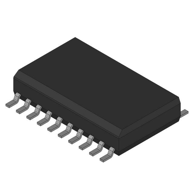
- Part No.:
- TCM29C13DW
- Manufacturer:
- Texas Instruments
- Category:
- CODECS
- Package:
- -
- Datasheet:
-
 TCM29C13DW.pdf
- Description:
- PCM CODEC, A/MU-LAW, 1-FUNC
- Quantity:
- Payment:

- Shipping:

Inventory:8,411
Please send an inquiry. Send us your inquiry, and we will respond immediately.
Product details
Overview
TCM29C13DW from Texas Instruments is a single-chip PCM codec and line filter for full-duplex voice telephony interfaces, supporting µ-law coding, 2.048 MHz fixed-data-rate operation, 24-pin SOIC (DW) package, 0°C to 70°C temperature range, and direct replacement of Intel 2913 in T1/PABX line interface applications.
For engineers reviewing the TCM29C13DW datasheet, TCM29C13DW pinout, TCM29C13DW application, or TCM29C13DW equivalent, key selection criteria include µ-law PCM encoding/decoding capability, integrated transmit/receive filtering, low-power 80 mW operating mode, dual ±5 V supply support, and compatibility with TDM systems requiring 8-bit signaling and frame-sync timing.
Technical Context
The TCM29C13DW integrates A/D and D/A conversion with analog band-pass filtering for voice-band signals (200 Hz–3.4 kHz), using successive-approximation architecture and internal voltage references. It supports both fixed-data-rate (1.536/1.544/2.048 MHz) and variable-data-rate (64 kHz–2.048 MHz) modes via DCLKR/CLKSEL configuration.
Its analog front-end includes uncommitted operational amplifiers (ANLG IN+, ANLG IN−, GSX), programmable gain control (GSR), and differential power amplifier outputs (PWRO+, PWRO−). Digital interface uses TTL-compatible PCM IN/OUT, FSR/FSX frame sync, and TSX/DCLKX time-slot strobe/data clock with open-drain output capability in fixed mode.
Key Specifications
| Parameter | Value and Actual Design Meaning |
|---|---|
| Function | Single-chip PCM codec + analog line filter for voice-band telephony termination |
| Coding Standard | µ-law only (SIGX/ASEL tied to VCC or GND); not A-law capable |
| Operating Supply | ±5 V (VCC = 5 V ±5%, VBB = –5 V ±5%) - dual-rail CMOS operation |
| Power Consumption | 80 mW typical in active mode; 5 mW in power-down (PDN = low) |
| Temperature Range | 0°C to 70°C - commercial-grade specification (TCM29Cxx series) |
| Package | DW (SOIC-24) - surface-mount, 24-pin, 0.300-inch body width |
| Filter Bandwidth | Transmit/receive passband: 200 Hz to 3.4 kHz (±0.15 dB flatness), –30 dB attenuation at 4.6 kHz |
Pinout & Package
TCM29C13DW is housed in a 24-pin SOIC (DW) package with 0.300-inch body width and standard JEDEC MS-013 footprint. Pin numbering follows top-view orientation with Pin 1 at bottom-left corner.
| Pin/Terminal | Circuit Role | Design Meaning |
|---|---|---|
| VBB | Most negative supply rail | –5 V reference for analog section; all analog voltages referenced to ANLG GND, not DGTL GND |
| PWRO+, PWRO− | Differential power amplifier outputs | Drive transformer hybrids or high-Z loads directly; complementary outputs enable balanced line driving |
| PDN | Power-down control input | TTL-high enables device; TTL-low reduces supply current to 0.3–0.8 mA and disables all functional blocks |
| DCLKR | Receive data clock select | When tied to VBB → fixed-data-rate mode; otherwise → variable-mode receive clock input (64 kHz–2.048 MHz) |
| PCM IN | Serial PCM data input | 8-bit parallel-in/serial-out receive path; data latched on negative edges of CLKR (fixed) or DCLKR (variable) |
| FSR/TSRE | Frame sync/time-slot enable (receive) | Double-pulse = signaling frame; single-pulse = non-signaling; low >300 ms forces standby state |
| DGTL GND | Digital ground return | Isolated from ANLG GND to prevent digital noise coupling into voice path |
| VCC | Most positive supply rail | +5 V digital/analog reference; supplies logic, DAC, and internal references |
| GSX | Transmit op-amp output | Uncommitted output stage feeding transmit filter; configurable gain via external feedback |
| ANLG IN−, ANLG IN+ | Inverting/noninverting analog inputs | High-impedance (10 MΩ), low-offset (±25 mV) inputs for voice signal conditioning |
| ANLG GND | Analog ground return | Separate ground plane for all analog circuitry; no internal connection to DGTL GND |
| SIGX/ASEL | µ-law/A-law select | Tied to VCC/GND → µ-law; tied to VBB → A-law; TCM29C13 defaults to µ-law only |
| TSX/DCLKX | Time-slot strobe / transmit clock | Open-drain output in fixed mode (enables 3-state buffers); input as DCLKX in variable mode |
| PCM OUT | Serial PCM data output | 8-bit transmit data clocked out on positive edges of CLKX (fixed) or DCLKX (variable) |
| FSX/TSXE | Frame sync/time-slot enable (transmit) | Independent timing control for transmit channel; low >300 ms enters standby |
| CLKR/CLKX | Master clocks (receive/transmit) | Internally connected; frequency set by CLKSEL (VBB=2.048 MHz, GND=1.544 MHz, VCC=1.536 MHz) |
Key Features
| Feature | Design Value |
|---|---|
| No external components for sample/hold/autozero | Reduces BOM count and board space; eliminates external capacitor drift and calibration |
| Precision internal voltage references | Enables stable encode/decode accuracy across temperature without trimming resistors |
| Excellent PSRR (>30 dB up to 50 kHz) | Minimizes supply noise coupling into voice path - critical for clean telephony performance |
| Direct replacement for Intel 2913 | Enables drop-in upgrade in legacy T1/PABX designs without PCB or firmware changes |
| Loopback test capability (ANLG LOOP) | Supports automated production testing by internally connecting PWRO+ to ANLG IN |
Applications
| Line Interface for T1 Carrier Systems | Subscriber Line Concentrator |
|---|---|
Use Scenario: Interfacing analog telephone lines to digital T1 carrier multiplexers in central office switching equipment. IC Role / Device Role / Timing Role: Performs A/D encoding of voice, D/A decoding of received PCM, and analog filtering per CCITT G.712 requirements. Use Value: Eliminates discrete codec + filter combinations; meets 36 dB SINAD and <105 µs differential delay specs for T1 compliance. | Use Scenario: Aggregating multiple analog subscriber lines into a shared digital backplane in remote concentrators. IC Role / Device Role / Timing Role: Provides simultaneous full-duplex PCM conversion for up to 24 channels using time-division multiplexing. Use Value: Enables compact, low-power concentrator design with integrated µ-law companding and 71 dB crosstalk attenuation. |
| Digital Encryption System Interface | Digital Voice-Band Data Storage |
Use Scenario: Bridging analog encrypted voice signals to digital encryption modules in secure telephony terminals. IC Role / Device Role / Timing Role: Digitizes analog encrypted audio prior to cipher processing; reconstructs decrypted audio for analog output. Use Value: Maintains end-to-end signal fidelity with <15 dBrnC0 transmit noise and C-message weighted receive noise ≤11 dBrnC0. | Use Scenario: Recording and playback of voice-band signals in embedded voice loggers or IVR systems. IC Role / Device Role / Timing Role: Converts analog speech to 8-bit µ-law PCM for storage; decodes stored PCM for playback. Use Value: Delivers 30 dB signal-to-distortion ratio down to –40 dBm0 input level, preserving intelligibility in compressed storage. |
Equivalent & Alternatives
The following parts are listed as comparable options for similar PCM codec and filter applications.
| Alternative Part | Technical Difference | Application Difference | Selection Advice |
|---|---|---|---|
| TCM129C13DW | Extended temperature range (–40°C to 85°C); identical pinout, µ-law coding, and electrical specs | Required for industrial or outdoor telecom infrastructure where ambient exceeds 70°C | Select TCM129C13DW when operating outside commercial temperature limits; otherwise TCM29C13DW suffices |
| MC145508P | Single-supply (+5 V only), no VBB rail; A-law/µ-law selectable; 20-pin PDIP package | Lacks differential power outputs and integrated loopback; requires external op-amps for line driving | Choose MC145508P only for cost-sensitive, single-rail designs where board space and analog integration are secondary |
Compared with TCM129C13DW, the TCM29C13DW offers identical functionality at lower cost but excludes extended temperature support; versus MC145508P, it provides superior analog integration, differential outputs, and lower system-level component count despite higher pin count.
Availability
TCM29C13DW is available at Aetrix Electronics and suitable for T1 carrier line interface, PABX subscriber concentrators, and digital encryption system design requiring stable component supply, long-term obsolescence management, and traceable sourcing.
Supply support for TCM29C13DW includes scheduled delivery planning, volume procurement assistance, BOM continuity management, traceable sourcing, and lifecycle availability coordination for OEM customers, industrial embedded developers, connected-device designers, and electronics production programs.
Manufacturer
Texas Instruments is a global semiconductor leader founded in 1930, specializing in analog, embedded processing, and connectivity solutions for industrial, automotive, and communications markets.
The TCM29C13DW belongs to TI's legacy telephony codec family designed specifically for digital voice infrastructure - emphasizing low-noise analog performance, µ-law/A-law compliance, and seamless integration into TDM-based switching and transmission systems.
FAQ
What is the primary function of the TCM29C13DW in a telephony system?
The TCM29C13DW serves as a combined PCM encoder/decoder and analog line filter, performing A/D conversion of analog voice signals and D/A reconstruction of received PCM data while applying band-pass filtering compliant with CCITT G.712. It interfaces analog telephone circuits with TDM digital networks, enabling full-duplex voice transmission in systems like T1 carriers and PABX switches. The TCM29C13DW integrates all required functions - including sample/hold, autozero, and precision references - eliminating external components.
Does the TCM29C13DW support both µ-law and A-law coding standards?
The TCM29C13DW supports µ-law coding exclusively. Its SIGX/ASEL pin must be tied to VCC or GND to select µ-law operation; tying it to VBB would enable A-law, but the TCM29C13DW datasheet explicitly states that A-law is not supported for this variant. The TCM29C17 and TCM129C17 are the designated A-law versions in the same family. Therefore, the TCM29C13DW is strictly a µ-law device and cannot be configured for A-law without hardware redesign.
What are the power supply requirements for reliable operation of the TCM29C13DW?
The TCM29C13DW requires dual supplies: VCC = +5 V ±5% and VBB = –5 V ±5%, both referenced to their respective ground planes (DGTL GND and ANLG GND). Digital and analog grounds must remain isolated to prevent noise coupling. Operating current is 7–9 mA from VCC and –7 to –9 mA from VBB under typical 2.048 MHz conditions. Power-down mode (PDN = low) reduces total dissipation to 3–8 mW. Exceeding ±5.25 V on either rail violates absolute maximum ratings and risks permanent damage.
How does the TCM29C13DW handle timing synchronization in fixed-data-rate mode?
In fixed-data-rate mode, the TCM29C13DW uses CLKR and CLKX (internally connected) as master clocks, with frequency selected via CLKSEL (VBB = 2.048 MHz, GND = 1.544 MHz, VCC = 1.536 MHz). Frame synchronization is managed by FSR/TSRE and FSX/TSXE, which must be phase-locked to their respective clocks. The device expects double-pulse signaling frames and single-pulse nonsignaling frames, and enters standby if FSR or FSX remains low for >300 ms. All timing parameters - including setup/hold times and pulse widths - are specified in the datasheet for 2.048 MHz operation.
Can the TCM29C13DW drive a telephone line transformer directly?
Yes, the TCM29C13DW can drive a telephone line transformer directly using its differential power amplifier outputs PWRO+ and PWRO−. These outputs support 300 Ω load impedance and deliver sufficient current to interface with standard hybrid transformers in line interface applications. The device specifies output resistance of 1 Ω and offset voltage of 80–180 mV (single-ended), enabling robust common-mode rejection. No external buffer stages are needed, though external passive components may be required for impedance matching depending on transformer specifications.
TCM29C13DW Specifications
- Product attributes
- Attribute value
- Manufacturer:
- Texas Instruments
- Series:
- *
- Package/Case:
- -
- Packaging:
- Bulk
- Product Status:
- Active
- Type:
- -
- Data Interface:
- -
- Resolution (Bits):
- -
- Number of ADCs / DACs:
- -
- Sigma Delta:
- -
- S/N Ratio, ADCs / DACs (db) Typ:
- -
- Dynamic Range, ADCs / DACs (db) Typ:
- -
- Voltage - Supply, Analog:
- -
- Voltage - Supply, Digital:
- -
- Operating Temperature:
- -
- Grade:
- -
- Qualification:
- -
- Mounting Type:
- -
- Supplier Device Package:
- -
TCM29C13DW FAQ
1.How can I place an order for TCM29C13DW through Aetrix?
Please submit a Request for Quotation (RFQ) for TCM29C13DW on Aetrix. Our sales agent will provide a competitive quotation and guide you through the order confirmation once you accept the terms.
2.Are the price and stock information for TCM29C13DW reliable?
The price and inventory of TCM29C13DW are updated periodically and may fluctuate due to market conditions. Stock and pricing data are typically refreshed every 24 hours. Quotation validity for TCM29C13DW is usually 5 days.
3.What payment methods are accepted for TCM29C13DW?
We accept Wire Transfer, PayPal, Credit Card, Western Union, MoneyGram, and Escrow for TCM29C13DW transactions.
Note: Certain payment methods may incur a processing fee.
4.How is shipping managed for TCM29C13DW?
TCM29C13DW orders can be shipped via leading logistics carriers, including DHL, UPS, FedEx, TNT, or Registered Mail.
Once your TCM29C13DW order is processed, you will receive an email with the shipment details and tracking number.
Note: Tracking information may take up to 24 hours to appear. Express delivery typically takes 3–5 business days.
5.How can I obtain technical support or documentation for TCM29C13DW?
For technical support, including TCM29C13DW datasheets, pinout diagrams, or application guidance, please contact our engineering support team. They can provide detailed documentation and assistance for your TCM29C13DW requirements.
6.How does Aetrix verify that TCM29C13DW is sourced from the original manufacturer or authorized distributors?
All TCM29C13DW products on Aetrix are procured from qualified distributors and authorized channels. Our dedicated quality assurance team conducts strict verification, including traceability checks and, if necessary, third-party testing. This ensures that TCM29C13DW meets industry standards.
7.What is the process for return or replacement of TCM29C13DW?
All TCM29C13DW units undergo pre-shipment inspection (PSI). If there is an issue with TCM29C13DW, returns or replacements are accepted under the following conditions:
1.Quantity discrepancies, incorrect items, or visible external defects (such as breakage or corrosion), acknowledged by Aetrix.
2.The issue is reported within 90 days of delivery.
3.The TCM29C13DW part is unused and in its original packaging.
Return procedure for TCM29C13DW:
1.Submit a request within 90 days.
2.Obtain a Return Material Authorization (RMA) from Aetrix.
TCM29C13DW Tags
-
NAU88C22YG
Nuvoton Technology Corporation

-
TLV320AIC3100IRHBR
Texas Instruments
-
DA7212-01UM2
Renesas
-
NAU8810YG
Nuvoton Technology Corporation
-
DA7218-00U32
Renesas
-
CMX655DQ6-TR1K
CML Micro
-
SGTL5000XNLA3
NXP Semiconductors
-
TLV320AIC3104IRHBR
Texas Instruments
-
MAX9867EWV+T
Analog Devices Inc./Maxim Integrated

-
MAX9860ETG+T
Analog Devices Inc./Maxim Integrated

-
TLV320AIC3106IRGZR
Texas Instruments
-
SGTL5000XNLA3R2
NXP Semiconductors
Tech Hub

A practical engineering guide to 3.3V and 5V logic compatibility, input thresholds, resistor dividers, translator ICs, MOSFET level shifting, I2C pull-ups, timing limits and power-sequencing risks.

The 74HC595 uses push-pull logic outputs, while the TPIC6B595 uses 50 V open-drain DMOS sinks for higher-power loads. This guide compares timing, current limits, 3.3 V interfacing, load wiring, thermal…

The 74HC595 converts serial data into eight stable parallel outputs. This guide covers pin functions, shift and storage timing, OE and MR behavior, drive-current limits, cascading, voltage compatibilit…

A technical comparison of level-sensitive latches and edge-triggered flip-flops, covering timing windows, setup and hold limits, master–slave operation, time borrowing, race-through, HDL inference and…

A D latch stores one bit while Enable controls when data can pass. This reference covers gate-level operation, truth tables, transparency, setup and hold timing, LE versus OE, common ICs and practical …

An SR latch stores one bit through cross-coupled feedback. This engineering reference covers NOR and NAND implementations, truth tables, forbidden-state recovery, gated operation, switch debouncing, fa…

Latch circuits retain one bit through feedback. This technical reference covers SR and D latches, truth tables, transparency, timing limits, latch-versus-flip-flop behavior, applications and common log…

An engineering guide to LED driver operation, constant-current and constant-voltage outputs, linear and switching topologies, dimming, IC selection, calculations, replacement compatibility, and fault c…

Operational amplifier guide covering op amp basics, feedback, ideal vs real op amps, common configurations, buffer circuits, offset, bias current, gain-bandwidth, slew rate, rail-to-rail limits and sel…

Jumper cables guide covering safe connection order, red and black clamp placement, final ground connection, cable gauge, length, clamp quality, copper vs CCA cables, jump starter comparison and battery…


