
 My Inquiry
 My Account


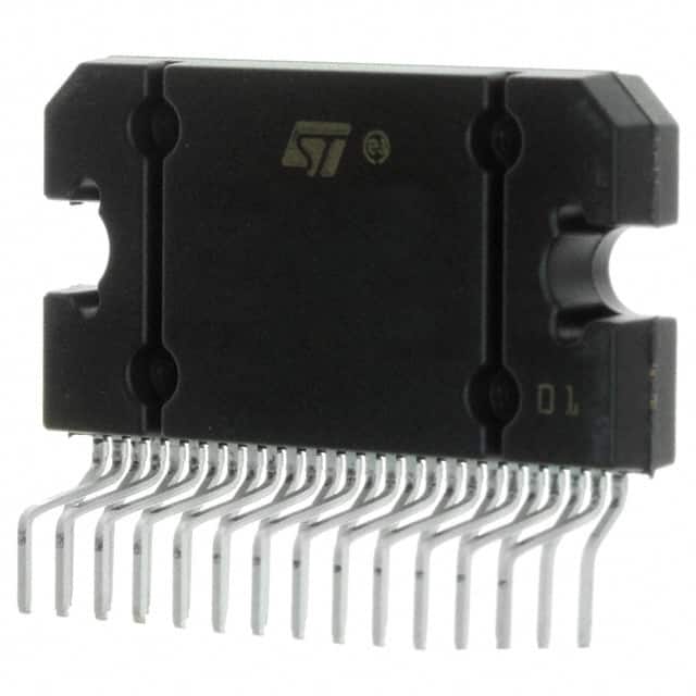
STMicroelectronics TDA7801H
- Part No.:
- TDA7801H
- Manufacturer:
- STMicroelectronics
- Category:
- Audio Special Purpose
- Package:
- 27-Flexiwatt, Formed Leads
- Datasheet:
-
 TDA7801H.pdf
- Description:
- IC AMP D QUAD 72W 27FLEXIWATT
- Quantity:
- Payment:

- Shipping:

Inventory:3,565
Please send an inquiry. Send us your inquiry, and we will respond immediately.
Product details
Overview
TDA7801H from STMicroelectronics is a BCD6-technology quad bridge Class-D audio power amplifier with integrated 110 dB D/A conversion, I²S digital input (44.1–192 kHz sampling), and full I²C diagnostics for automotive infotainment systems. It delivers 4×28 W into 4 Ω at 14.4 V (10% THD) and features MOSFET outputs, independent channel short-circuit protection, and linear thermal warnings.
For engineers reviewing the TDA7801H datasheet, TDA7801H pinout, TDA7801H application, or TDA7801H equivalent, key selection criteria include its Flexiwatt27 horizontal package compatibility, dual-mode I²C/legacy operation, speaker-level DC/AC load detection, and configurable gain (four levels) for low-noise line-out functionality.
Technical Context
The TDA7801H implements a fully balanced transresistance output stage per channel using BCD6 process technology, enabling co-integration of high-resolution D/A conversion (115 dB S/N) and robust MOSFET power stages. Its diagnostic architecture supports real-time per-channel fault reporting-including open-load, short-to-rail, clipping, and thermal events-via dedicated I²C registers and an open-drain CD/DIAG pin.
It operates in three configurable modes: amplifier (full output), tristate (outputs disabled), and standby (minimal quiescent current). The PLL-filter/ENABLE pin serves dual roles: loop filter capacitor connection and global enable control, while I²C address selection (two options) and 8-channel TDM support are exclusive to PowerSO36-not applicable to TDA7801H's Flexiwatt27 package.
Key Specifications
| Parameter | Value and Actual Design Meaning |
|---|---|
| Output Power | 4×28 W @ 4 Ω, 14.4 V, 1 kHz, 10% THD - sufficient for mid-range car audio front/rear speaker drive without external heatsinking |
| Max Output Power | 4×72 W @ 2 Ω - enables high-SPL subwoofer or low-impedance tweeter support with appropriate thermal management |
| D/A Resolution | 110 dB integrated conversion - achieves 115 dB system S/N ratio, critical for premium audio head units with low-noise analog signal chains |
| I²S Input Support | 3.3/1.8 V logic, TDM option, 44.1–192 kHz sampling - compatible with modern SoC audio processors and supports high-res playback |
| I²C Diagnostics | Per-channel DC offset, AC load, clipping, thermal warning, and POR reporting - eliminates need for external sense circuitry in OEM diagnostic compliance |
| Fault Protection | Four independent short-circuit protections + linear thermal warnings - ensures fail-safe operation across all four channels under asymmetric load faults |
| Enable Interface | CMOS-compatible (3.3/5 V) ENABLE pin - allows direct interfacing with microcontroller GPIOs without level-shifting |
Pinout & Package
Package: Flexiwatt27 (horizontal), thermally enhanced through-tab GND mounting, suitable for surface-mount assembly with vertical heat dissipation orientation.
| Pin/Terminal | Circuit Role | Design Meaning |
|---|---|---|
| 1 (TAB) | Thermal pad / GND | Primary heat path to PCB ground plane; must be soldered to large copper area for thermal compliance |
| 2 (Pll-filter / ENABLE) | PLL loop filter / global enable | Connects external RC filter for clock stability; pulled high to activate amplifier mode |
| 4 & 6 (OUT2− / OUT2+) | Channel 2 differential output | Drives left-rear speaker; requires symmetrical PCB routing to minimize EMI |
| 8 & 10 (OUT1− / OUT1+) | Channel 1 differential output | Drives left-front speaker; shares Vcc (Pin 7) and PW_GND (Pin 9) with Channel 2 |
| 18 & 20 (OUT3+ / OUT3−) | Channel 3 differential output | Drives right-front speaker; powered by separate Vcc (Pin 21) and PW_GND (Pin 19) |
| 22 & 24 (OUT4+ / OUT4−) | Channel 4 differential output | Drives right-rear speaker; monitored by CD/DIAG (Pin 23) for fault reporting |
| 23 (CD/DIAG) | Open-drain diagnostic output | Asserts low on overcurrent, thermal warning, or POR; requires external pull-up for I²C-compatible interrupt signaling |
| 26 (I2C Data) | I²C bidirectional data / legacy mute | In I²C mode: serial data line; in legacy mode: active-low mute control |
| 27 (I2C Clock) | I²C clock / legacy enable | In I²C mode: serial clock; in legacy mode: active-high enable for amplifier operation |
Key Features
| Feature | Design Value |
|---|---|
| Integrated D/A converter | 110 dB resolution enables 115 dB system S/N - reduces external DAC count and board space in head unit designs |
| Per-channel diagnostics | I²C-accessible registers report DC offset, AC load status, clipping, and thermal warnings - supports automated speaker health monitoring in telematics systems |
| Selectable gain (4 levels) | Configurable via I²C to optimize SNR for line-out or speaker-drive use cases - avoids external attenuators or op-amp buffers |
| Independent soft-play/mute | Front/rear channel mute control via I²C - enables fade/balance functions without MCU intervention |
| Full fault protection suite | Four independent short-circuit protections plus linear thermal warnings - prevents latch-up and catastrophic failure during speaker wire faults |
Applications
| Automotive Infotainment Head Unit | Multi-Zone Cabin Audio System |
|---|---|
Use Scenario: Integrated audio processor in OEM head unit delivering 4-channel output to front/rear speakers. IC Role / Device Role / Timing Role: Quad bridge amplifier with embedded D/A conversion and I²C diagnostics - replaces discrete DAC + amplifier + protection IC stack. Use Value: Reduces BOM count by 3–4 components and enables real-time speaker fault logging for warranty analytics and predictive maintenance. | Use Scenario: Central audio hub distributing distinct content to driver, front passenger, and rear seat zones. IC Role / Device Role / Timing Role: Four independent Class-D channels with configurable gain and mute - supports zone-specific volume leveling and mute scheduling. Use Value: Eliminates need for external analog switches or relays; I²C programmability allows dynamic reassignment of channels to zones via firmware. |
| Aftermarket Car Stereo Amplifier Module | Commercial Vehicle Entertainment System |
Use Scenario: Compact 4-channel amplifier module for retrofit installations with limited chassis space. IC Role / Device Role / Timing Role: High-efficiency MOSFET output stage with thermal warning pins - enables fanless operation in sealed enclosures. Use Value: 4×28 W output at 14.4 V meets DIN-standard power requirements while maintaining <1.5 W quiescent draw in standby mode. | Use Scenario: Ruggedized audio system in buses or RVs subject to wide temperature swings and vibration. IC Role / Device Role / Timing Role: BCD6 process-based IC with linear thermal protection and ESD-hardened I/O - withstands automotive-grade environmental stress per AEC-Q100. Use Value: Full fault reporting via CD/DIAG pin simplifies field diagnostics; no external thermal sensors required for compliance with ISO 16750-4. |
Equivalent & Alternatives
The following parts are listed as comparable options for similar quad-channel automotive audio amplifier applications.
| Alternative Part | Technical Difference | Application Difference | Selection Advice |
|---|---|---|---|
| TDA7801PD | PowerSO36 package with slug-up thermal interface; supports two I²C addresses and 8-channel TDM mode | Preferred for automated SMT lines requiring tape-and-reel packaging and higher channel density in compact layouts | Select when board space is constrained and TDM audio routing is needed; not pin-compatible with TDA7801H |
| TDA7802 | Same Flexiwatt27 footprint but adds 32-bit I²S support, improved THD+N (0.008% vs. 0.01%), and extended 384 kHz sampling | Targeted at premium head units requiring ultra-low distortion and future-proof high-res audio capability | Choose for next-gen designs where THD+N and sampling flexibility outweigh cost sensitivity |
Compared with TDA7801PD, TDA7801H offers lower assembly cost and simpler thermal design for manual or semi-automated assembly, while TDA7802 provides measurable THD+N and sampling rate improvements at higher BOM cost-making TDA7801H optimal for cost-sensitive mid-tier automotive audio platforms.
Availability
TDA7801H is available at Aetrix Electronics and suitable for automotive infotainment head units, aftermarket stereo modules, and commercial vehicle entertainment systems requiring stable component supply across multi-year production cycles.
Supply support for TDA7801H includes scheduled delivery planning, volume procurement assistance, BOM continuity management, traceable sourcing, and lifecycle availability coordination for OEM customers, industrial embedded developers, connected-device designers, and electronics production programs.
Manufacturer
STMicroelectronics is a global semiconductor leader headquartered in Geneva, specializing in automotive, industrial, and power management ICs with broad AEC-Q100-qualified product portfolios.
The TDA7801H belongs to ST's TDA7xxx automotive audio amplifier family, designed specifically for cost-effective, diagnostics-rich, quad-channel amplification in entry-to-mid-tier car radios and head units.
FAQ
What is the maximum junction temperature and thermal resistance (RthJA) for TDA7801H in Flexiwatt27 horizontal package?
The TDA7801H has a maximum junction temperature of 150 °C. For the Flexiwatt27 horizontal package, the typical junction-to-ambient thermal resistance (RthJA) is 45 °C/W with a 200 cm² 2-oz copper heatsink area. This value assumes standard PCB layout per ST's AN4501 guidelines-reduced RthJA is achievable with enhanced copper pour and thermal vias under the tab.
Does TDA7801H support I²S data alignment modes other than standard MSB-first, left-justified format?
No. The TDA7801H accepts only standard I²S format (MSB-first, left-justified, WS high for left channel) as defined in Section 7.2 of the datasheet. It does not support right-justified, DSP, or PCM modes. TDM operation is supported but requires specific SD1_3/SD2_4 timing and is functionally distinct from alternate I²S alignments.
Can the CD/DIAG pin be used to trigger an interrupt on a microcontroller without external components?
Yes-the CD/DIAG pin is an open-drain output with internal 20 kΩ pull-down. To interface with a 3.3 V microcontroller GPIO configured as interrupt input, connect a 4.7 kΩ external pull-up to 3.3 V. The pin asserts low on any fault event (clipping, thermal warning, short-circuit, or POR), and debouncing must be handled in firmware due to transient pulse durations as short as 10 µs.
Is the "legacy mode" electrically identical to I²C mode, or does it disable diagnostic functionality?
Legacy mode disables I²C communication and diagnostic register access entirely. In this mode, the I2C Data (Pin 26) acts as active-low mute, and I2C Clock (Pin 27) acts as active-high enable. All diagnostics-including CD/DIAG pin reporting-are retained, but configuration (gain, soft-mute, etc.) becomes static and fixed at power-on defaults.
TDA7801H Specifications
- Product attributes
- Attribute value
- Manufacturer:
- STMicroelectronics
- Series:
- -
- Package/Case:
- 27-Flexiwatt, Formed Leads
- Packaging:
- Tube
- Product Status:
- Obsolete
- Function:
- Audio Amplifier
- Applications:
- Audio
- Number of Channels:
- 4
- Interface:
- I2C, I2S, TDM
- Voltage - Supply:
- 8V ~ 18V
- Operating Temperature:
- -40°C ~ 105°C (TA)
- Specifications:
- 115dB
- Mounting Type:
- Through Hole
- Grade:
- Automotive
TDA7801H FAQ
1.How can I place an order for TDA7801H through Aetrix?
Please submit a Request for Quotation (RFQ) for TDA7801H on Aetrix. Our sales agent will provide a competitive quotation and guide you through the order confirmation once you accept the terms.
2.Are the price and stock information for TDA7801H reliable?
The price and inventory of TDA7801H are updated periodically and may fluctuate due to market conditions. Stock and pricing data are typically refreshed every 24 hours. Quotation validity for TDA7801H is usually 5 days.
3.What payment methods are accepted for TDA7801H?
We accept Wire Transfer, PayPal, Credit Card, Western Union, MoneyGram, and Escrow for TDA7801H transactions.
Note: Certain payment methods may incur a processing fee.
4.How is shipping managed for TDA7801H?
TDA7801H orders can be shipped via leading logistics carriers, including DHL, UPS, FedEx, TNT, or Registered Mail.
Once your TDA7801H order is processed, you will receive an email with the shipment details and tracking number.
Note: Tracking information may take up to 24 hours to appear. Express delivery typically takes 3–5 business days.
5.How can I obtain technical support or documentation for TDA7801H?
For technical support, including TDA7801H datasheets, pinout diagrams, or application guidance, please contact our engineering support team. They can provide detailed documentation and assistance for your TDA7801H requirements.
6.How does Aetrix verify that TDA7801H is sourced from the original manufacturer or authorized distributors?
All TDA7801H products on Aetrix are procured from qualified distributors and authorized channels. Our dedicated quality assurance team conducts strict verification, including traceability checks and, if necessary, third-party testing. This ensures that TDA7801H meets industry standards.
7.What is the process for return or replacement of TDA7801H?
All TDA7801H units undergo pre-shipment inspection (PSI). If there is an issue with TDA7801H, returns or replacements are accepted under the following conditions:
1.Quantity discrepancies, incorrect items, or visible external defects (such as breakage or corrosion), acknowledged by Aetrix.
2.The issue is reported within 90 days of delivery.
3.The TDA7801H part is unused and in its original packaging.
Return procedure for TDA7801H:
1.Submit a request within 90 days.
2.Obtain a Return Material Authorization (RMA) from Aetrix.
TDA7801H Tags

-
SA571DR2G
onsemi

-
ADAU7002ACBZ-R7
Analog Devices Inc.

-
DRV135UA/2K5
Texas Instruments

-
DRV134UA/1K
Texas Instruments

-
DRV134PA
Texas Instruments
-
DRV134UA
Texas Instruments
-
DRV135UA
Texas Instruments
-
SA572DR2G
onsemi
-
PGA2311U/1K
Texas Instruments

-
SI8244BB-D-IS1R
Skyworks Solutions Inc.

-
CS8416K-CZZR
Cirrus Logic Inc.

-
SRC4392IPFBR
Texas Instruments
Tech Hub

A practical engineering guide to 3.3V and 5V logic compatibility, input thresholds, resistor dividers, translator ICs, MOSFET level shifting, I2C pull-ups, timing limits and power-sequencing risks.

The 74HC595 uses push-pull logic outputs, while the TPIC6B595 uses 50 V open-drain DMOS sinks for higher-power loads. This guide compares timing, current limits, 3.3 V interfacing, load wiring, thermal…

The 74HC595 converts serial data into eight stable parallel outputs. This guide covers pin functions, shift and storage timing, OE and MR behavior, drive-current limits, cascading, voltage compatibilit…

A technical comparison of level-sensitive latches and edge-triggered flip-flops, covering timing windows, setup and hold limits, master–slave operation, time borrowing, race-through, HDL inference and…

A D latch stores one bit while Enable controls when data can pass. This reference covers gate-level operation, truth tables, transparency, setup and hold timing, LE versus OE, common ICs and practical …

An SR latch stores one bit through cross-coupled feedback. This engineering reference covers NOR and NAND implementations, truth tables, forbidden-state recovery, gated operation, switch debouncing, fa…

Latch circuits retain one bit through feedback. This technical reference covers SR and D latches, truth tables, transparency, timing limits, latch-versus-flip-flop behavior, applications and common log…

An engineering guide to LED driver operation, constant-current and constant-voltage outputs, linear and switching topologies, dimming, IC selection, calculations, replacement compatibility, and fault c…

Operational amplifier guide covering op amp basics, feedback, ideal vs real op amps, common configurations, buffer circuits, offset, bias current, gain-bandwidth, slew rate, rail-to-rail limits and sel…

Jumper cables guide covering safe connection order, red and black clamp placement, final ground connection, cable gauge, length, clamp quality, copper vs CCA cables, jump starter comparison and battery…


