
 My Inquiry
 My Account


STMicroelectronics TDA7808-48X
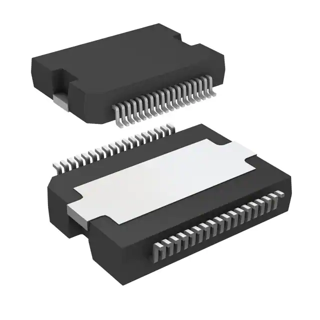
- Part No.:
- TDA7808-48X
- Manufacturer:
- STMicroelectronics
- Category:
- Audio Special Purpose
- Package:
- PowerSO-36 Exposed Top Pad
- Datasheet:
-
 TDA7808-48X.pdf
- Description:
- ABD AUDIO & POWER
- Quantity:
- Payment:

- Shipping:

Inventory:3,840
Please send an inquiry. Send us your inquiry, and we will respond immediately.
Product details
Overview
TDA7808-48X from STMicroelectronics is an AEC-Q100 qualified quad-channel Class-AB+SB-I automotive audio power amplifier in Flexiwatt27 (vertical) package, delivering 4 × 27 W into 4 Ω at 14.4 V with 115 dB A-weighted dynamic range and start-stop compatibility down to 6 V supply. It integrates a 24-bit digital input interface (I2S/TDM), programmable PLL, offset/clipping detection, and thermal protection for OEM infotainment systems.
For engineers reviewing the TDA7808-48X datasheet, TDA7808-48X pinout, TDA7808-48X application, or TDA7808-48X equivalent, this page provides verified pin functions, SB-I efficiency behavior, I2S/TDM 4/8/16-channel timing, mute/transient pop-free operation, and Flexiwatt27 thermal derating data - all critical for automotive audio BOM validation and layout planning.
Technical Context
The TDA7808 implements a hybrid Class-AB architecture enhanced by ST's SB-I (Switched-Bias Improved) high-efficiency mode, dynamically adjusting bias current to reduce dissipation up to 50% versus conventional Class AB under real-world music signals. Its integrated 24-bit DAC achieves 115 dB SNR and >110 dB dynamic range without external oversampling.
A fully programmable PLL locks to input sample rates of 44.1/48/96/192 kHz (64×Fs), enabling jitter-tolerant digital audio synchronization. The device supports independent front/rear play/mute control, selectable digital gains for low-noise line-out, and open-drain CD/DIAG pin for per-channel clipping diagnostics - all configurable via I²C bus.
Key Specifications
| Parameter | Value and Actual Design Meaning |
|---|---|
| Output Power | 4 × 27 W @ 4 Ω, 14.4 V, 1 kHz, THD = 10% - sufficient for full-range speaker drive in compact automotive head units |
| Dynamic Range | 115 dB (A-weighted) - enables high-fidelity reproduction with minimal noise floor masking |
| Supply Range | 6–18.5 V - supports start-stop battery profiles and cold-crank conditions without shutdown |
| Digital Input | I2S, TDM 4ch/8ch/16ch (8+8) - compatible with SoC audio processors and multi-zone DSP architectures |
| Quiescent Current | 210 mA (amplifier mode, mute), 40 mA (ECO mode) - enables low-power standby for always-on audio features |
| THD+N | 0.015% @ 4 W, 1 kHz (SB-I mode) - meets OEM requirements for distortion-limited mid-bass fidelity |
| Crosstalk | 100 dB @ 1 kHz - ensures channel separation for discrete surround sound decoding |
Pinout & Package
Package: Flexiwatt27 (Vertical), thermally enhanced through-tab mounting; Rth j-case = 1 °C/W max. Tab is electrically connected to PGND and must be soldered to PCB ground plane for thermal and EMI performance.
| Pin | Circuit Role | Design Meaning |
|---|---|---|
| 1 (TAB) | Power Ground / Thermal Slug | Primary heat path to PCB; must be connected to large copper area for 85 W dissipation capability |
| 2 (STBY) | Standby Control Input | CMOS-compatible active-low enable; pulls device into <1 μA standby state when high |
| 3 (WS) | I2S Word Select | Left/right channel framing signal; level-triggered, supports 1.8 V/3.3 V logic |
| 4 (OUT2+) | Channel 2 Positive Output | Bridge-tied load (BTL) output driving left rear speaker + terminal; ±3 A peak current capable |
| 5 (PWGND2) | Channel 2 Power Ground | Dedicated low-impedance return path for OUT2±; minimizes crosstalk vs. other channels |
| 6 (OUT2−) | Channel 2 Negative Output | BTL output driving left rear speaker − terminal; complements OUT2+ for 27 W delivery |
| 7 (VCC12) | Channels 1 & 2 Supply | Separate 6–18.5 V rail for front-left/rear-left outputs; decoupling required per datasheet Fig. 3 |
| 8 (OUT1−) | Channel 1 Negative Output | BTL output for left front speaker −; paired with OUT1+ (Pin 10) in differential configuration |
| 9 (PWGND1) | Channel 1 Power Ground | Isolated return for front-left channel; prevents ground bounce coupling into analog section |
| 10 (OUT1+) | Channel 1 Positive Output | BTL output for left front speaker +; delivers 27 W into 4 Ω when combined with OUT1− |
| 11 (SCK) | I2S Serial Clock | Bit-clock input for digital audio frame sync; supports 1.8 V/3.3 V logic; max 10 MHz |
| 12 (SD24) | I2S Data Ch2/Ch4 | Time-division multiplexed serial data input for rear channels; shares SCK/WS with SD13 |
| 13 (SD13) | I2S Data Ch1/Ch3 | Time-division multiplexed serial data input for front channels; supports I2S/TDM formats |
| 14 (DGND) | Digital Ground | Reference for I2S/I2C logic; must be star-connected to AGND at single point near A3V3/D3V3 |
| 15 (AGND) | Analog Ground | Reference for DAC, analog filters, and output stages; isolated from DGND except at filter caps |
| 16 (D3V3) | Digital 3.3 V Filter | Input for internal 3.3 V digital regulator; requires ≥10 μF ceramic + 100 nF bypass per datasheet |
| 17 (A3V3) | Analog 3.3 V Filter | Input for internal 3.3 V analog regulator; separate from D3V3 to suppress digital noise coupling |
| 18 (OUT3+) | Channel 3 Positive Output | BTL output for right front speaker +; driven from VCC34 (Pin 21) and PWGND3 (Pin 19) |
| 19 (PWGND3) | Channel 3 Power Ground | Dedicated return for right front channel; routed separately to minimize inter-channel interference |
| 20 (OUT3−) | Channel 3 Negative Output | BTL output for right front speaker −; completes bridge with OUT3+ for full 27 W output |
| 21 (VCC34) | Channels 3 & 4 Supply | Second independent 6–18.5 V rail for front-right/rear-right outputs; enables split-rail thermal management |
| 22 (OUT4−) | Channel 4 Negative Output | BTL output for right rear speaker −; pairs with OUT4+ (Pin 24) in push-pull configuration |
| 23 (PWGND4) | Channel 4 Power Ground | Isolated return for rear-right channel; maintains channel independence in 4-zone audio systems |
| 24 (OUT4+) | Channel 4 Positive Output | BTL output for right rear speaker +; delivers rated 27 W into 4 Ω load with low THD |
| 25 (CD/DIAG) | Clipping/Diagnostic Output | Open-drain flag indicating per-channel clipping or thermal fault; pulled up externally to 3.3 V |
| 26 (SDA) | I2C Data Line | Bidirectional I2C bus data; supports standard/fast-mode (100/400 kHz); 1.8 V/3.3 V tolerant |
| 27 (SCL) | I2C Clock Line | I2C bus clock input; requires external pull-up; synchronized with STBY for safe register access |
Key Features
| Feature | Design Value |
|---|---|
| SB-I High-Efficiency Mode | Reduces average power dissipation by up to 50% vs. Class AB under real audio program material, extending heatsink life in confined dash spaces |
| Start-Stop Compatibility | Operates continuously from 6 V to 18.5 V, eliminating audio dropouts during engine cranking or idle-stop cycles in Euro 6/LEV III vehicles |
| Independent Front/Rear Mute | Enables zone-specific audio muting (e.g., rear seat entertainment disable) without affecting front cabin playback or DSP processing |
| Offset & Clipping Detection | On-chip analog comparators monitor DC offset (±25 mV) and output clipping per channel, feeding diagnostic alerts via CD/DIAG pin |
| Pop-Free Transitions | Hardware-controlled ramping of bias and output stage enables mute-to-play transitions with <100 μs pop suppression - no external soft-start needed |
Applications
| Automotive Infotainment Head Unit | Multi-Zone Rear Seat Entertainment |
|---|---|
|
Use Scenario: Integrated 4-channel amplifier in OEM head unit powering front door and rear parcel shelf speakers. IC Role / Device Role / Timing Role: Quad BTL output stage with integrated 24-bit DAC and SB-I bias control; synchronizes to SoC's I2S clock via programmable PLL. Use Value: Eliminates external DAC and discrete MOSFET H-bridges, reducing BOM count by 12 components while maintaining 115 dB SNR and 6 V start-stop operation. |
Use Scenario: Dedicated rear amplifier module receiving TDM 8-channel stream from central gateway for dual-screen video playback. IC Role / Device Role / Timing Role: Digital-input audio processor with independent front/rear mute and per-channel clipping detection; uses TDM 8ch format for time-aligned audio routing. Use Value: Enables simultaneous playback of two different audio streams (e.g., movies + navigation) with hardware-level channel isolation and diagnostic visibility. |
| Aftermarket DSP Integration | Compact EV Sound System |
|
Use Scenario: DSP-equipped aftermarket stereo using TDA7808-48X as final output stage for tuned cabin acoustics. IC Role / Device Role / Timing Role: Precision gain-matched quad amplifier with selectable digital gains (GV1–GV4) and 1.8 V I2S interface for low-voltage DSP co-design. Use Value: Provides 0.015% THD+N at 4 W and 100 dB crosstalk - preserving DSP-generated EQ and time-alignment corrections without degradation. |
Use Scenario: Space-constrained electric vehicle audio system requiring high efficiency and thermal resilience in battery-pack-proximate locations. IC Role / Device Role / Timing Role: Start-stop compatible Class-AB+SB-I amplifier with 1 °C/W junction-to-case thermal resistance; operates at full 27 W/channel with 70 °C case temperature. Use Value: Delivers 4 × 27 W output while dissipating ≤42 W average power (vs. 84 W Class AB), reducing cooling demands and enabling smaller heatsinks. |
Equivalent & Alternatives
The following parts are listed as comparable options for similar quad-channel automotive audio amplifier applications.
| Alternative Part | Technical Difference | Application Difference | Selection Advice |
|---|---|---|---|
| TDA7808-ZST | Same die, PowerSO-36 (slug-up) package with 36-pin layout and ADD pin for I²C address selection | Supports four I²C addresses; better thermal performance (lower Rth j-case) but requires larger PCB footprint | Select for designs needing multi-device I²C bus sharing or higher continuous power delivery with heatsink mounting |
| MAX9768A | Class D quad amplifier (not SB-I); 4 × 25 W @ 4 Ω; 90 dB SNR; no integrated DAC; requires external digital interface | Lacks 24-bit DAC, SB-I efficiency, and start-stop voltage range; optimized for ultra-low quiescent power, not fidelity | Select only when board space and efficiency outweigh SNR and analog integration requirements |
Compared with TDA7808-ZST, the TDA7808-48X trades I²C address flexibility and thermal margin for compact Flexiwatt27 form factor and simplified layout; versus MAX9768A, it delivers 25 dB higher SNR and true start-stop operation but consumes more quiescent current in ECO mode.
Availability
TDA7808-48X is available at Aetrix Electronics and suitable for automotive infotainment head units, rear-seat entertainment modules, and compact EV sound systems requiring stable component supply across extended production lifecycles.
Supply support for TDA7808-48X includes scheduled delivery planning, volume procurement assistance, BOM continuity management, traceable sourcing, and lifecycle availability coordination for OEM customers, industrial embedded developers, connected-device designers, and electronics production programs.
Manufacturer
STMicroelectronics is a global semiconductor leader headquartered in Geneva, Switzerland, designing and manufacturing automotive-grade ICs with AEC-Q100 qualification and functional safety compliance.
The TDA7808 belongs to ST's automotive audio power amplifier product line, engineered specifically for high-fidelity, start-stop compatible infotainment systems requiring integrated DAC, digital interface, and thermal robustness in constrained spaces.
FAQ
What is the minimum supply voltage for continuous operation of TDA7808-48X?
The TDA7808-48X operates continuously from 6 V to 18.5 V, making it fully compatible with automotive start-stop battery profiles. Below 6 V, the internal power-on reset circuit disables amplification to prevent unstable operation; recovery occurs automatically once VS rises above 6 V with proper hysteresis.
Does TDA7808-48X require external I²C pull-up resistors?
Yes - external 4.7 kΩ pull-up resistors to 3.3 V are required on both SDA (Pin 26) and SCL (Pin 27) lines per I²C specification and ST's layout guidelines. These ensure reliable communication at up to 400 kHz and prevent bus contention during STBY transitions.
How is thermal protection implemented in TDA7808-48X?
Thermal protection uses on-die temperature sensing with automatic foldback: when junction temperature exceeds 150 °C, output stage bias is reduced to limit power dissipation; if temperature persists above threshold, the device enters thermal shutdown and asserts CD/DIAG. Recovery is automatic after cooldown below 140 °C.
Can TDA7808-48X drive 2 Ω loads?
No - the device is characterized and guaranteed only for 4 Ω and higher loads per datasheet Table 6. Driving 2 Ω loads risks overcurrent triggering, excessive junction temperature rise beyond Rth j-case limits, and potential damage due to uncontrolled current peaks during transients.
TDA7808-48X Specifications
- Product attributes
- Attribute value
- Manufacturer:
- STMicroelectronics
- Series:
- -
- Package/Case:
- PowerSO-36 Exposed Top Pad
- Packaging:
- Tube
- Product Status:
- Active
- Function:
- Audio Amplifier
- Applications:
- Audio
- Number of Channels:
- 4
- Interface:
- I2C, I2S, TDM
- Voltage - Supply:
- 6V ~ 18.5V
- Operating Temperature:
- -40°C ~ 105°C (TA)
- Specifications:
- 115dB
- Mounting Type:
- Surface Mount
- Grade:
- Automotive
TDA7808-48X FAQ
1.How can I place an order for TDA7808-48X through Aetrix?
Please submit a Request for Quotation (RFQ) for TDA7808-48X on Aetrix. Our sales agent will provide a competitive quotation and guide you through the order confirmation once you accept the terms.
2.Are the price and stock information for TDA7808-48X reliable?
The price and inventory of TDA7808-48X are updated periodically and may fluctuate due to market conditions. Stock and pricing data are typically refreshed every 24 hours. Quotation validity for TDA7808-48X is usually 5 days.
3.What payment methods are accepted for TDA7808-48X?
We accept Wire Transfer, PayPal, Credit Card, Western Union, MoneyGram, and Escrow for TDA7808-48X transactions.
Note: Certain payment methods may incur a processing fee.
4.How is shipping managed for TDA7808-48X?
TDA7808-48X orders can be shipped via leading logistics carriers, including DHL, UPS, FedEx, TNT, or Registered Mail.
Once your TDA7808-48X order is processed, you will receive an email with the shipment details and tracking number.
Note: Tracking information may take up to 24 hours to appear. Express delivery typically takes 3–5 business days.
5.How can I obtain technical support or documentation for TDA7808-48X?
For technical support, including TDA7808-48X datasheets, pinout diagrams, or application guidance, please contact our engineering support team. They can provide detailed documentation and assistance for your TDA7808-48X requirements.
6.How does Aetrix verify that TDA7808-48X is sourced from the original manufacturer or authorized distributors?
All TDA7808-48X products on Aetrix are procured from qualified distributors and authorized channels. Our dedicated quality assurance team conducts strict verification, including traceability checks and, if necessary, third-party testing. This ensures that TDA7808-48X meets industry standards.
7.What is the process for return or replacement of TDA7808-48X?
All TDA7808-48X units undergo pre-shipment inspection (PSI). If there is an issue with TDA7808-48X, returns or replacements are accepted under the following conditions:
1.Quantity discrepancies, incorrect items, or visible external defects (such as breakage or corrosion), acknowledged by Aetrix.
2.The issue is reported within 90 days of delivery.
3.The TDA7808-48X part is unused and in its original packaging.
Return procedure for TDA7808-48X:
1.Submit a request within 90 days.
2.Obtain a Return Material Authorization (RMA) from Aetrix.
TDA7808-48X Tags

-
SA571DR2G
onsemi

-
ADAU7002ACBZ-R7
Analog Devices Inc.

-
DRV135UA/2K5
Texas Instruments

-
DRV134UA/1K
Texas Instruments

-
DRV134PA
Texas Instruments
-
DRV134UA
Texas Instruments
-
DRV135UA
Texas Instruments
-
SA572DR2G
onsemi
-
PGA2311U/1K
Texas Instruments

-
SI8244BB-D-IS1R
Skyworks Solutions Inc.

-
CS8416K-CZZR
Cirrus Logic Inc.

-
SRC4392IPFBR
Texas Instruments
Tech Hub

A practical engineering guide to 3.3V and 5V logic compatibility, input thresholds, resistor dividers, translator ICs, MOSFET level shifting, I2C pull-ups, timing limits and power-sequencing risks.

The 74HC595 uses push-pull logic outputs, while the TPIC6B595 uses 50 V open-drain DMOS sinks for higher-power loads. This guide compares timing, current limits, 3.3 V interfacing, load wiring, thermal…

The 74HC595 converts serial data into eight stable parallel outputs. This guide covers pin functions, shift and storage timing, OE and MR behavior, drive-current limits, cascading, voltage compatibilit…

A technical comparison of level-sensitive latches and edge-triggered flip-flops, covering timing windows, setup and hold limits, master–slave operation, time borrowing, race-through, HDL inference and…

A D latch stores one bit while Enable controls when data can pass. This reference covers gate-level operation, truth tables, transparency, setup and hold timing, LE versus OE, common ICs and practical …

An SR latch stores one bit through cross-coupled feedback. This engineering reference covers NOR and NAND implementations, truth tables, forbidden-state recovery, gated operation, switch debouncing, fa…

Latch circuits retain one bit through feedback. This technical reference covers SR and D latches, truth tables, transparency, timing limits, latch-versus-flip-flop behavior, applications and common log…

An engineering guide to LED driver operation, constant-current and constant-voltage outputs, linear and switching topologies, dimming, IC selection, calculations, replacement compatibility, and fault c…

Operational amplifier guide covering op amp basics, feedback, ideal vs real op amps, common configurations, buffer circuits, offset, bias current, gain-bandwidth, slew rate, rail-to-rail limits and sel…

Jumper cables guide covering safe connection order, red and black clamp placement, final ground connection, cable gauge, length, clamp quality, copper vs CCA cables, jump starter comparison and battery…


