
 My Inquiry
 My Account


NXP Semiconductors TDA8024T/C1,118
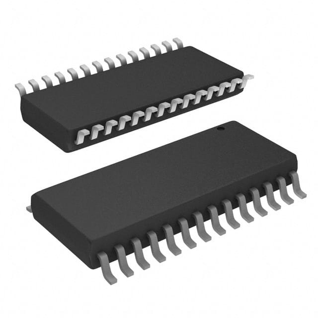
- Part No.:
- TDA8024T/C1,118
- Manufacturer:
- NXP Semiconductors
- Category:
- Specialized
- Package:
- 28-SOIC (0.295", 7.50mm Width)
- Datasheet:
-
 TDA8024T/C1,118.pdf
- Description:
- IC INTERFACE SPECIALIZED 28SO
- Quantity:
- Payment:

- Shipping:

Inventory:316
Please send an inquiry. Send us your inquiry, and we will respond immediately.
Product details
Overview
TDA8024T/C1,118 from NXP Semiconductors is a complete analog smart card interface IC designed to sit between ISO 7816-compliant cards and host microcontrollers. It delivers regulated 3 V or 5 V card supply (VCC), provides three protected bidirectional I/O lines (C4/C7/C8), integrates a 26 MHz crystal oscillator, and supports synchronous clock division (÷1/2/4/8) - enabling secure banking card readers and EMV payment terminals.
For engineers reviewing the TDA8024T/C1,118 datasheet, TDA8024T/C1,118 pinout, TDA8024T/C1,118 application, or TDA8024T/C1,118 equivalent, this device serves as a drop-in solution for ISO 7816-3 compliant systems requiring thermal/short-circuit protection, ESD-hardened card contacts (>6 kV), automatic activation/deactivation sequencing, and DC-to-DC VCC generation from 4–6.5 V VDDP input.
Technical Context
The TDA8024T/C1,118 implements a dual-mode DC-to-DC converter that operates as either a voltage doubler or follower depending on VDDP and selected VCC (3 V or 5 V). Its integrated 26 MHz oscillator feeds a programmable clock divider (CLKDIV1/CLKDIV2) to generate precise card clocks up to 20 MHz with guaranteed 45–55% duty cycle and synchronous frequency transitions.
Three identical buffered I/O transceivers (I/O, AUX1, AUX2) feature active pull-up circuitry delivering >1 mA at 0.9×VCC into 80 pF loads, with internal current limiting (15 mA max) and 1 MHz bandwidth. Fault detection includes short-circuit, card removal, VDD dropout, and thermal events - all triggering automatic deactivation sequences controlled via CMDVCC and monitored by the NMOS OFF output.
Key Specifications
| Parameter | Value and Actual Design Meaning |
|---|---|
| VCC Output | Regulated 3.0 V ±5% or 5.0 V ±5%; supplies ISO 7816 cards with ≤65 mA (3 V) or ≤80 mA (5 V) continuous load. |
| VDDP Input Range | 4.0–6.5 V for 5 V VCC mode; 3.0–6.5 V for 3 V VCC mode - enables flexible system-level power architecture. |
| Card Clock | Up to 20 MHz derived from 26 MHz internal oscillator; selectable ÷1/2/4/8 via CLKDIV1/CLKDIV2 with synchronous switching. |
| I/O Protection | Thermal and short-circuit protection on all card contacts; >6 kV HBM ESD rating on I/O, RST, CLK, AUX1/AUX2, PRES pins. |
| Activation Control | Hardware/software-initiated sequence via CMDVCC (active LOW); automatic deactivation on fault or VDD drop-out. |
| Package | SO28 (SOT136-1), 7.5 mm body width - compatible with standard surface-mount assembly and IPC-7351B footprint. |
| Operating Temp | −25 °C to +85 °C ambient - validated for industrial and commercial embedded smart card reader environments. |
Pinout & Package
Package: SO28 (SOT136-1), plastic small outline, 28 leads, 7.5 mm body width, lead pitch 0.6 mm.
| Pin/Terminal | Circuit Role | Design Meaning |
|---|---|---|
| 1, 2 | CLKDIV1 / CLKDIV2 | Inputs selecting card clock frequency (÷1/2/4/8); must not change simultaneously - minimum 10 ns delay required. |
| 3 | 5V/3V | Logic-level input setting VCC output: HIGH = 5 V, LOW = 3 V - configures DC-to-DC converter operating mode. |
| 4, 7 | PGND / S1 | DC-to-DC converter ground and capacitor connection node; requires 100 nF low-ESR (<100 mΩ) capacitor to S2 (pin 5). |
| 6 | VDDP | Separate 4–6.5 V supply input for DC-to-DC converter - isolated from VDD to prevent noise coupling to host logic. |
| 9, 10 | PRES / PRES | Redundant card presence inputs (active LOW/HIGH); include built-in 8 ms debounce to suppress mechanical switch bounce. |
| 11–13 | I/O / AUX1 / AUX2 | Three half-duplex bidirectional data lines to card contacts C7/C4/C8; each has 11 kΩ pull-up to VCC and 15 mA current limit. |
| 15 | CLK | Output clock signal to card contact C3; driven from internal oscillator with synchronous frequency changes and 45–55% duty cycle. |
| 16 | RST | Open-drain reset output to card contact C2; enabled after t5 in activation sequence and synchronized to CLK timing. |
| 17 | VCC | Regulated card supply output (3 V or 5 V); requires dual decoupling: 100 nF + 220 nF (or 2×100 nF) to CGND with ESR <100 mΩ. |
| 18 | PORADJ | Power-on reset threshold adjustment input; accepts external resistor bridge to double POR pulse width to ~16 ms (not used in TDA8024AT). |
| 19 | CMDVCC | Host command input (active LOW) initiating full activation/deactivation sequence - controls sequencer state machine. |
| 20 | RSTIN | Non-inverted host reset input; directly controls RST output after activation completes (t5), enabling precise ATR timing. |
| 21, 22 | VDD / GND | Main IC supply (2.7–6.5 V) and ground reference for all host-side signals - must also power connected microcontroller. |
| 23 | OFF | NMOS interrupt output (active LOW); indicates card presence when CMDVCC=HIGH, or fault condition (short, overtemp, card removal) when CMDVCC=LOW. |
| 24, 25 | XTAL1 / XTAL2 | Crystal oscillator connections for 26 MHz fundamental-mode crystal; XTAL2 open if external clock applied to XTAL1. |
| 26–28 | I/OUC / AUX1UC / AUX2UC | Host-side I/O lines referenced to VDD (not VCC); enable level-shifting between host MCU and card logic domains. |
Key Features
| Feature | Design Value |
|---|---|
| ISO 7816-3 Compliance | Fully implements asynchronous T=0 protocol timing, VCC regulation, clock generation, and reset control per ISO/IEC 7816-3:2006. |
| EMV & GSM11.11 Support | Validated for payment systems (EMV Level 1) and SIM card interfaces (GSM 11.11), including ATR handling and voltage/frequency requirements. |
| Integrated DC-to-DC Converter | Generates stable 3 V or 5 V VCC from single 4–6.5 V VDDP rail - eliminates need for external LDO or charge pump in compact readers. |
| Automatic Sequencing Logic | Hardware-managed activation (t0–t5) and deactivation (t10–tde) with precise timing windows - reduces firmware complexity and ensures compliance. |
| Card-Side ESD Robustness | 6 kV HBM ESD protection on all card-facing pins (I/O, RST, CLK, AUX1/AUX2, PRES) - exceeds ISO 7816-3 and IEC 61000-4-2 Level 4. |
| Supply Supervision | Detects VDD drop-out and initiates emergency deactivation; PORADJ pin allows external threshold tuning for custom reset behavior. |
Applications
| Banking Card Reader | EMV Payment Terminal |
|---|---|
|
Use Scenario: Desktop or portable terminal reading credit/debit cards in retail or ATM environments. IC Role / Device Role / Timing Role: Provides ISO 7816-compliant analog interface, regulates VCC, generates CLK, manages RST, and handles card insertion/removal detection. Use Value: Enables single-chip replacement of discrete analog front-end components while meeting EMV Level 1 certification requirements for voltage accuracy, timing jitter, and fault recovery. |
Use Scenario: Integrated point-of-sale (POS) system processing chip-and-PIN transactions with contact smart cards. IC Role / Device Role / Timing Role: Acts as certified smart card controller interface, delivering synchronized 5 MHz clock, 5 V VCC, and hardware-sequenced reset for secure ATR exchange. Use Value: Reduces BOM count and layout area vs. discrete solutions; built-in overload detection (≈120 mA) prevents false card removal triggers during high-current ATR phases. |
| Secure ID Reader | Pay-TV Conditional Access |
|
Use Scenario: Government or enterprise access control system authenticating national ID or e-passport chips. IC Role / Device Role / Timing Role: Interfaces with ICAO-compliant e-passports using 3 V VCC and 4 MHz clock; manages dual PRES inputs for tamper-resistant card detection. Use Value: Dual-presence inputs with 8 ms hardware debounce eliminate false triggers from mechanical wear; 3 V operation meets ICAO 9303 Part 10 low-power requirements. |
Use Scenario: Set-top box reading conditional access modules (CAMs) for encrypted broadcast content. IC Role / Device Role / Timing Role: Supplies regulated 3 V or 5 V to CAM, generates precise clock for DES/Triple-DES cryptographic handshakes, and monitors VDD stability during key loading. Use Value: Thermal and short-circuit protection prevents CAM damage during hot-plug events; OFF pin provides direct fault signaling to host MCU without polling overhead. |
Equivalent & Alternatives
The following parts are listed as comparable options for similar smart card interface applications.
| Alternative Part | Technical Difference | Application Difference | Selection Advice |
|---|---|---|---|
| TDA8024AT/C1,118 | No PORADJ pin connection; fixed 8 ms POR pulse width; otherwise identical pinout, specs, and functionality. | Suitable where external reset threshold adjustment is unnecessary; eliminates need for external resistor divider network. | Select TDA8024AT/C1,118 when simplified power-on reset behavior suffices and board space for R1/R2 is constrained. |
| TDA8024TT/C1,118 | TSSOP28 package (SOT361-1), 4.4 mm body width; identical electrical specs but smaller footprint and different thermal resistance (100 K/W). | Better suited for space-constrained portable readers; requires requalification of thermal performance under high-current card loads. | Choose TDA8024TT/C1,118 when PCB area is critical and thermal derating analysis confirms safe operation at 80 mA VCC load. |
Compared with TDA8024AT/C1,118, the TDA8024T/C1,118 offers adjustable POR timing via PORADJ for tighter system-level reset coordination, while TDA8024TT/C1,118 trades thermal performance for miniaturization - making the SO28 variant optimal for cost-sensitive, thermally robust fixed-form-factor readers.
Availability
TDA8024T/C1,118 is available at Aetrix Electronics and suitable for banking card readers, EMV payment terminals, and secure ID authentication systems requiring stable component supply, long-term lifecycle support, and ISO 7816-3 compliance.
Supply support for TDA8024T/C1,118 includes scheduled delivery planning, volume procurement assistance, BOM continuity management, traceable sourcing, and lifecycle availability coordination for OEM customers, industrial embedded developers, connected-device designers, and electronics production programs.
Manufacturer
NXP Semiconductors is a global semiconductor leader specializing in secure connectivity solutions for automotive, industrial, and identification markets, with deep expertise in smart card and NFC technologies.
The TDA8024 series belongs to NXP's dedicated smart card interface product line, engineered specifically for ISO 7816-3 compliant contact-based card readers in payment, identity, and conditional access applications.
FAQ
What is the maximum continuous current the TDA8024T/C1,118 can deliver to a smart card?
The TDA8024T/C1,118 delivers up to 80 mA continuously at 5 V VCC or 65 mA at 3 V VCC. Its internal overload detector activates at approximately 120 mA, allowing brief current spikes (e.g., during ATR) without triggering deactivation - a design feature confirmed in the Quick Reference Data table and Functional Description section of the datasheet for TDA8024T/C1,118.
Does the TDA8024T/C1,118 support both 3 V and 5 V smart cards in the same design?
Yes, the TDA8024T/C1,118 supports both 3 V and 5 V cards via the 5V/3V pin (pin 3): driving it HIGH selects 5 V VCC output, LOW selects 3 V. The DC-to-DC converter automatically adapts its topology (voltage follower or doubler) based on VDDP and the selected VCC - a capability explicitly defined in Section 8.1 and Table 4 of the TDA8024T/C1,118 datasheet.
How does the TDA8024T/C1,118 handle card insertion and removal detection?
The TDA8024T/C1,118 uses dual redundant PRES inputs (pins 9 and 10) with built-in 8 ms hardware debounce to detect card presence. When either PRES signal asserts, the device initiates activation; on card removal, it triggers immediate deactivation. This behavior is documented in Sections 7.2 (Pin Description) and 8.10 (Fault Detection) of the TDA8024T/C1,118 datasheet.
Can the TDA8024T/C1,118 generate a 4 MHz clock for EMV transactions?
Yes, the TDA8024T/C1,118 generates precise 4 MHz clock signals using its 26 MHz internal oscillator and programmable divider. Setting CLKDIV1=1 and CLKDIV2=0 yields fXTAL/4 = 6.5 MHz; for exact 4 MHz, an external 32 MHz crystal may be used on XTAL1/XTAL2 - though the datasheet confirms 20 MHz max card clock, and 4 MHz falls well within guaranteed 45–55% duty cycle and synchronous transition specifications for TDA8024T/C1,118.
What is the purpose of the PORADJ pin on the TDA8024T/C1,118?
The PORADJ pin (pin 18) on the TDA8024T/C1,118 allows external adjustment of the Power-on Reset (POR) threshold using a resistor divider, doubling the POR pulse width from ~8 ms to ~16 ms. This pin is unconnected in the TDA8024AT variant. Its function and implementation are fully detailed in Sections 7.2, 8.2.2, and Figure 1 of the TDA8024T/C1,118 datasheet.
TDA8024T/C1,118 Specifications
- Product attributes
- Attribute value
- Manufacturer:
- NXP Semiconductors
- Series:
- -
- Package/Case:
- 28-SOIC (0.295", 7.50mm Width)
- Packaging:
- Tape & Reel (TR)
- Product Status:
- Obsolete
- Applications:
- -
- Interface:
- Analog
- Voltage - Supply:
- 2.7V ~ 6.5V
- Supplier Device Package:
- 28-SO
- Grade:
- -
- Qualification:
- -
- Mounting Type:
- Surface Mount
TDA8024T/C1,118 FAQ
1.How can I place an order for TDA8024T/C1,118 through Aetrix?
Please submit a Request for Quotation (RFQ) for TDA8024T/C1,118 on Aetrix. Our sales agent will provide a competitive quotation and guide you through the order confirmation once you accept the terms.
2.Are the price and stock information for TDA8024T/C1,118 reliable?
The price and inventory of TDA8024T/C1,118 are updated periodically and may fluctuate due to market conditions. Stock and pricing data are typically refreshed every 24 hours. Quotation validity for TDA8024T/C1,118 is usually 5 days.
3.What payment methods are accepted for TDA8024T/C1,118?
We accept Wire Transfer, PayPal, Credit Card, Western Union, MoneyGram, and Escrow for TDA8024T/C1,118 transactions.
Note: Certain payment methods may incur a processing fee.
4.How is shipping managed for TDA8024T/C1,118?
TDA8024T/C1,118 orders can be shipped via leading logistics carriers, including DHL, UPS, FedEx, TNT, or Registered Mail.
Once your TDA8024T/C1,118 order is processed, you will receive an email with the shipment details and tracking number.
Note: Tracking information may take up to 24 hours to appear. Express delivery typically takes 3–5 business days.
5.How can I obtain technical support or documentation for TDA8024T/C1,118?
For technical support, including TDA8024T/C1,118 datasheets, pinout diagrams, or application guidance, please contact our engineering support team. They can provide detailed documentation and assistance for your TDA8024T/C1,118 requirements.
6.How does Aetrix verify that TDA8024T/C1,118 is sourced from the original manufacturer or authorized distributors?
All TDA8024T/C1,118 products on Aetrix are procured from qualified distributors and authorized channels. Our dedicated quality assurance team conducts strict verification, including traceability checks and, if necessary, third-party testing. This ensures that TDA8024T/C1,118 meets industry standards.
7.What is the process for return or replacement of TDA8024T/C1,118?
All TDA8024T/C1,118 units undergo pre-shipment inspection (PSI). If there is an issue with TDA8024T/C1,118, returns or replacements are accepted under the following conditions:
1.Quantity discrepancies, incorrect items, or visible external defects (such as breakage or corrosion), acknowledged by Aetrix.
2.The issue is reported within 90 days of delivery.
3.The TDA8024T/C1,118 part is unused and in its original packaging.
Return procedure for TDA8024T/C1,118:
1.Submit a request within 90 days.
2.Obtain a Return Material Authorization (RMA) from Aetrix.
TDA8024T/C1,118 Tags

-
NVT4857UKAZ
NXP Semiconductors

-
TCA8418RTWR
Texas Instruments

-
PCA9546APWR
Texas Instruments

-
MD0100N8-G
Microchip Technology

-
PCA9548APW,118
NXP Semiconductors

-
PCA9540BDP,118
NXP Semiconductors

-
PCA9548APWR
Texas Instruments

-
PCA9546APW,118
NXP Semiconductors

-
PTN3360DBS,518
NXP Semiconductors

-
PCA9546ABS,118
NXP Semiconductors

-
PCA9518PWR
Texas Instruments

-
PCA9545APW,118
NXP Semiconductors
Tech Hub

A practical engineering guide to 3.3V and 5V logic compatibility, input thresholds, resistor dividers, translator ICs, MOSFET level shifting, I2C pull-ups, timing limits and power-sequencing risks.

The 74HC595 uses push-pull logic outputs, while the TPIC6B595 uses 50 V open-drain DMOS sinks for higher-power loads. This guide compares timing, current limits, 3.3 V interfacing, load wiring, thermal…

The 74HC595 converts serial data into eight stable parallel outputs. This guide covers pin functions, shift and storage timing, OE and MR behavior, drive-current limits, cascading, voltage compatibilit…

A technical comparison of level-sensitive latches and edge-triggered flip-flops, covering timing windows, setup and hold limits, master–slave operation, time borrowing, race-through, HDL inference and…

A D latch stores one bit while Enable controls when data can pass. This reference covers gate-level operation, truth tables, transparency, setup and hold timing, LE versus OE, common ICs and practical …

An SR latch stores one bit through cross-coupled feedback. This engineering reference covers NOR and NAND implementations, truth tables, forbidden-state recovery, gated operation, switch debouncing, fa…

Latch circuits retain one bit through feedback. This technical reference covers SR and D latches, truth tables, transparency, timing limits, latch-versus-flip-flop behavior, applications and common log…

An engineering guide to LED driver operation, constant-current and constant-voltage outputs, linear and switching topologies, dimming, IC selection, calculations, replacement compatibility, and fault c…

Operational amplifier guide covering op amp basics, feedback, ideal vs real op amps, common configurations, buffer circuits, offset, bias current, gain-bandwidth, slew rate, rail-to-rail limits and sel…

Jumper cables guide covering safe connection order, red and black clamp placement, final ground connection, cable gauge, length, clamp quality, copper vs CCA cables, jump starter comparison and battery…


