
 My Inquiry
 My Account


NXP Semiconductors TDF5140AP/C1,112
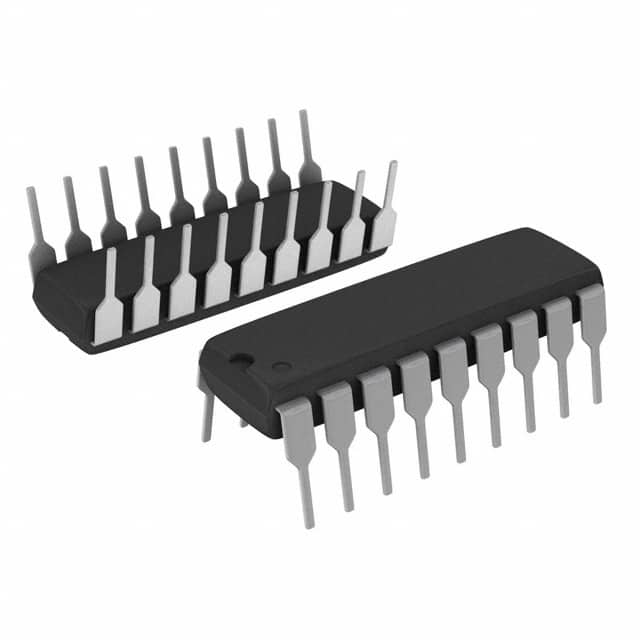
- Part No.:
- TDF5140AP/C1,112
- Manufacturer:
- NXP Semiconductors
- Category:
- Motor Drivers, Controllers
- Package:
- 18-DIP (0.300", 7.62mm)
- Datasheet:
-
 TDF5140AP/C1,112.pdf
- Description:
- IC MOTOR DRIVER 4V-18V 18DIP
- Quantity:
- Payment:

- Shipping:

Inventory:1,956
Please send an inquiry. Send us your inquiry, and we will respond immediately.
Product details
Overview
TDF5140AP/C1,112 from NXP Semiconductors (formerly Philips Semiconductors) is a bipolar 18-pin DIL brushless DC motor driver IC enabling sensorless full-wave commutation for 3-phase BLDC motors. It delivers 0.8 A typical output current per phase, integrates flyback diodes and thermal shutdown, and provides tacho (FG) and position generator (PG) outputs - used in VCR scanner drive systems requiring precise rotor position sensing without Hall sensors.
For engineers reviewing the TDF5140AP/C1,112 datasheet, TDF5140AP/C1,112 pinout, TDF5140AP/C1,112 application, or TDF5140AP/C1,112 equivalent, this page details its back-EMF-based commutation logic, adaptive delay timing architecture, transconductance amplifier interface, and motor control design constraints including VMOT voltage range, current limiting thresholds, and thermal protection activation at 140 °C.
Technical Context
The TDF5140AP/C1,112 implements sensorless commutation using motor back-EMF zero-crossing detection across three push-pull output stages (MOT1–MOT3), with adaptive commutation delay controlled by external capacitors CAP-CD and CAP-DC. Its internal timing relies on CAP-ST (start oscillator), CAP-TI (watchdog timer), and CAP-DC (delay copy), each with defined sink/source currents and switching thresholds.
It integrates an uncommitted operational transconductance amplifier (OTA) with ±650 nA input bias, 0.3 S transfer gain, and 40 mA open-collector sink capability (AMP OUT), alongside dual-function PG/FG output (open-collector, negative-going edge valid) that combines frequency generation and external position pulse multiplexing - critical for VCR and laser printer motor synchronization.
Key Specifications
| Parameter | Value and Actual Design Meaning |
|---|---|
| Supply Voltage (VP) | 4–18 V - supports unstabilized supplies; powers control circuitry independently of motor voltage rail. |
| Motor Supply Input (VVMOT) | 1.7–20 V - separate high-current path for output driver stages; decouples motor power from logic supply. |
| Output Current (ILIM) | 0.7–1.0 A - current limiting threshold set by external resistor (e.g., 3.9 Ω or 6.8 Ω); protects against overloads without external sense resistors. |
| Drop-Out Voltage (VDO) | 0.93–1.05 V @ 100 mA - low saturation voltage enables efficient operation at high load currents with minimal heat dissipation. |
| Thermal Shutdown (TSD) | 130–150 °C - local transistor-level thermal protection triggers shutdown; recovery requires ≥30 K temperature drop before restart. |
| FG Output Frequency Ratio | 1:2 vs. commutation frequency - provides accurate tacho signal at half the electrical commutation rate; negative-going edges serve as microprocessor interrupts. |
| OTA Transfer Gain | 0.3 S - transconductance amplifier gain enables analog motor speed/torque control via external power transistor driven directly by AMP OUT. |
Pinout & Package
Package: 18-pin plastic dual in-line (DIL), SOT102, 22.0 × 7.8 mm body, 2.54 mm pitch. Lead finish: tin-lead (SnPb). Mounting compatible with wave/dip soldering (260 °C max, 5 s contact).
| Pin/Terminal | Circuit Role | Design Meaning |
|---|---|---|
| MOT1, MOT2, MOT3 | Push-pull motor phase outputs | Drive star- or delta-connected BLDC windings; include integrated flyback diodes (DH/DL) and current limiting. |
| MOT0 | Star-point input | Connects to motor neutral point for back-EMF sensing; essential for sensorless commutation in star-wound motors. |
| PG/FG | Open-collector digital output | Combines tacho (FG) pulses and external position (PG) marker pulses on single pin; negative edge valid for interrupt triggering. |
| +AMP IN / −AMP IN | OTA differential inputs | Accept control voltage signals (−0.3 to VP−1.7 V); enable analog speed regulation using external feedback network. |
| AMP OUT | OTA open-collector output | Sinks up to 40 mA; drives base/gate of external control transistor without buffer stage. |
| CAP-ST, CAP-TI, CAP-CD, CAP-DC | Timing capacitor terminals | Set start oscillator frequency (CAP-ST), watchdog timeout (CAP-TI), and adaptive commutation delay (CAP-CD/CAP-DC) via precise sink/source currents. |
Key Features
| Feature | Design Value |
|---|---|
| Sensorless full-wave commutation | Eliminates need for 3 Hall-effect sensors by detecting motor back-EMF zero-crossings at MOT1–MOT3; supports both star and delta motor configurations. |
| Built-in start-up oscillator | Generates initial commutation pulses when EMF is absent (e.g., stalled motor); resets upon first detected zero-crossing to transition to closed-loop operation. |
| Adaptive commutation delay | Adjusts timing between zero-crossing detection and next commutation using CAP-CD/CAP-DC; maintains optimal torque across varying motor loads and speeds. |
| Integrated thermal protection | Monitors junction temperature of each of six output transistors individually; shuts down affected channel only, preserving partial functionality during overload. |
| Transconductance amplifier (OTA) | Provides 40 mA sink capability and 0.3 S gain for direct analog control of external power transistors - enabling linear speed regulation without additional op-amps. |
Applications
| VCR Scanner Drive | Laser Beam Printer Motor Control |
|---|---|
Use Scenario: Precise bidirectional scanning motion in video cassette recorder head drum assemblies. IC Role / Device Role / Timing Role: TDF5140AP/C1,112 acts as the primary sensorless BLDC driver, generating FG pulses for speed lock and PG pulses for phase alignment with tape transport. Use Value: Eliminates Hall sensors and associated PCB routing; uses MOT0 star-point sensing and PG/FG multiplexing to reduce component count while maintaining <±1° mechanical phase accuracy. | Use Scenario: High-reliability paper feed and imaging drum rotation in office laser printers. IC Role / Device Role / Timing Role: TDF5140AP/C1,112 controls 3-phase BLDC motors driving rollers and drums, leveraging adaptive commutation delay to maintain torque consistency across variable paper weight and humidity conditions. Use Value: Built-in current limiting (0.8 A typ.) and thermal shutdown prevent motor stall damage; CAP-TI watchdog detects reverse rotation before misfeed occurs. |
| Fax Machine Paper Transport | Automotive Blower Fan Control |
Use Scenario: Continuous paper advancement and registration in thermal or inkjet fax mechanisms. IC Role / Device Role / Timing Role: TDF5140AP/C1,112 serves as compact motor driver with integrated tacho output (FG) feeding speed feedback to system MCU for closed-loop velocity control. Use Value: Low quiescent current (3.7 mA typ.) extends standby battery life; VMOT input allows independent motor rail (e.g., 12 V) while logic runs from 5 V VP supply. | Use Scenario: Cabin air blower fan requiring quiet, efficient, and EMI-robust motor control in automotive HVAC systems. IC Role / Device Role / Timing Role: TDF5140AP/C1,112 drives brushed or BLDC blower motors using back-EMF sensing; PG/FG output provides RPM telemetry to vehicle CAN gateway via opto-isolated interface. Use Value: Flyback diodes and thermal protection ensure reliability under high ambient temperatures (up to +70 °C operating ambient); SOT102 package withstands automotive vibration profiles. |
Equivalent & Alternatives
The following parts are listed as comparable options for similar brushless DC motor drive applications.
| Alternative Part | Technical Difference | Application Difference | Selection Advice |
|---|---|---|---|
| BA6886FM | Higher 1.5 A output current; built-in PWM controller; no OTA; different pinout and timing capacitor scheme. | Designed for higher-power fans and pumps; lacks PG/FG multiplexing and star-point (MOT0) input. | Select BA6886FM when >1 A peak current or integrated PWM dimming is required; not drop-in compatible due to differing commutation logic and pin assignment. |
| LB11685AV | Includes Hall sensor interface; supports both sensor-based and sensorless modes; 0.6 A output; different thermal shutdown threshold (150 °C fixed). | Used in automotive radiator fans where Hall sensors are preferred for startup reliability; lacks adaptive delay and OTA. | Choose LB11685AV for designs requiring guaranteed startup under zero-EMF conditions (e.g., cold cranking); requires external Hall sensors and redesign of timing network. |
Compared with BA6886FM and LB11685AV, the TDF5140AP/C1,112 uniquely balances sensorless robustness, analog control flexibility via OTA, and integrated PG/FG multiplexing - making it optimal for cost-sensitive, space-constrained VCR and printer applications where star-point sensing suffices and external transistor control is needed.
Availability
TDF5140AP/C1,112 is available at Aetrix Electronics and suitable for VCR scanner drive, laser printer motor control, fax machine paper transport, and automotive blower fan applications requiring stable component supply and long-term industrial availability.
Supply support for TDF5140AP/C1,112 includes scheduled delivery planning, volume procurement assistance, BOM continuity management, traceable sourcing, and lifecycle availability coordination for OEM customers, industrial embedded developers, connected-device designers, and electronics production programs.
Manufacturer
NXP Semiconductors is a global semiconductor company formed from the spin-off of Philips Semiconductors in 2006, specializing in secure connectivity solutions for automotive, industrial, and consumer markets.
The TDF5140AP/C1,112 belongs to NXP's legacy motor driver portfolio developed for cost-sensitive, high-reliability electromechanical systems - specifically targeting sensorless BLDC control in office automation and consumer audio/video equipment where integration, thermal resilience, and analog interface flexibility are critical.
FAQ
What is the function of the MOT0 pin on the TDF5140AP/C1,112?
The MOT0 pin on the TDF5140AP/C1,112 connects to the star-point (neutral) of a 3-phase BLDC motor winding and serves as the reference node for back-EMF zero-crossing detection. This enables sensorless commutation by allowing internal comparators to monitor voltage differences between each phase output (MOT1–MOT3) and MOT0. Without MOT0 connection, the TDF5140AP/C1,112 cannot perform its core sensorless function - it is mandatory for star-connected motors and unused (left open) for delta configurations.
How does the TDF5140AP/C1,112 achieve sensorless commutation without Hall sensors?
The TDF5140AP/C1,112 achieves sensorless commutation by continuously monitoring back-EMF voltages across motor windings using internal EMF comparators referenced to the MOT0 star-point. During each commutation state, one output is high-impedance (Z), allowing its winding's back-EMF to be measured. Zero-crossing detection triggers the adaptive commutation delay block, which calculates the optimal timing for the next state change. This eliminates Hall sensors while maintaining full-wave drive and torque stability across load variations - confirmed in the functional description and block diagram of the TDF5140AP/C1,112 datasheet.
What are the key timing capacitors for the TDF5140AP/C1,112 and their roles?
The TDF5140AP/C1,112 uses four dedicated timing capacitors: CAP-ST sets the start-up oscillator frequency (2 µA charge/discharge between 0.05–2.2 V); CAP-TI governs the watchdog timer for reverse-rotation detection (57 µA/5 µA/28 µA current sources); CAP-CD and CAP-DC jointly configure the adaptive commutation delay (8.1 µA/16.2 µA and 15.5 µA currents). Each capacitor has defined sink/source current specs and voltage thresholds - e.g., CAP-ST requires ~220 nF for 3 Hz startup, while CAP-TI ≥10 nF ensures reliable reverse-rotation blocking in VCR applications.
Can the TDF5140AP/C1,112 drive delta-connected BLDC motors?
Yes, the TDF5140AP/C1,112 can drive delta-connected BLDC motors, but MOT0 must be left unconnected (open) since delta configurations lack a physical star-point. The device's back-EMF sensing then operates differentially between phase outputs (e.g., MOT1–MOT2), though performance may vary slightly versus star-wound motors due to reduced common-mode rejection. The datasheet explicitly states compatibility with both star and delta connections, and the functional description confirms adaptive commutation logic functions regardless of winding topology - provided VMOT and VP rails meet voltage specifications.
What is the purpose of the PG/FG pin on the TDF5140AP/C1,112?
The PG/FG pin on the TDF5140AP/C1,112 is a multiplexed open-collector output delivering two distinct signals: standard tacho (FG) pulses at half the commutation frequency (for speed feedback), and position generator (PG) marker pulses (short 18 µs LOW pulses) synchronized to external pick-up coil input (PG IN). This dual functionality allows a single microprocessor pin to receive both RPM data and phase alignment markers - essential for VCR drum synchronization. The negative-going edge of every FG pulse is valid for interrupt generation, and the PG pulse is derived from MOT3 zero-crossing detection as specified in the timing diagrams.
TDF5140AP/C1,112 Specifications
- Product attributes
- Attribute value
- Manufacturer:
- NXP Semiconductors
- Series:
- -
- Package/Case:
- 18-DIP (0.300", 7.62mm)
- Packaging:
- Tube
- Product Status:
- Obsolete
- Motor Type - Stepper:
- -
- Motor Type - AC, DC:
- Brushless DC (BLDC)
- Function:
- Driver - Fully Integrated, Control and Power Stage
- Output Configuration:
- Half Bridge (3)
- Interface:
- Parallel
- Technology:
- Bipolar
- Step Resolution:
- -
- Applications:
- General Purpose
- Current - Output:
- 800mA
- Voltage - Supply:
- 4V ~ 18V
- Voltage - Load:
- 1.7V ~ 20V
- Operating Temperature:
- -30°C ~ 70°C (TA)
- Grade:
- -
- Qualification:
- -
- Mounting Type:
- Through Hole
- Supplier Device Package:
- 18-DIP
TDF5140AP/C1,112 FAQ
1.How can I place an order for TDF5140AP/C1,112 through Aetrix?
Please submit a Request for Quotation (RFQ) for TDF5140AP/C1,112 on Aetrix. Our sales agent will provide a competitive quotation and guide you through the order confirmation once you accept the terms.
2.Are the price and stock information for TDF5140AP/C1,112 reliable?
The price and inventory of TDF5140AP/C1,112 are updated periodically and may fluctuate due to market conditions. Stock and pricing data are typically refreshed every 24 hours. Quotation validity for TDF5140AP/C1,112 is usually 5 days.
3.What payment methods are accepted for TDF5140AP/C1,112?
We accept Wire Transfer, PayPal, Credit Card, Western Union, MoneyGram, and Escrow for TDF5140AP/C1,112 transactions.
Note: Certain payment methods may incur a processing fee.
4.How is shipping managed for TDF5140AP/C1,112?
TDF5140AP/C1,112 orders can be shipped via leading logistics carriers, including DHL, UPS, FedEx, TNT, or Registered Mail.
Once your TDF5140AP/C1,112 order is processed, you will receive an email with the shipment details and tracking number.
Note: Tracking information may take up to 24 hours to appear. Express delivery typically takes 3–5 business days.
5.How can I obtain technical support or documentation for TDF5140AP/C1,112?
For technical support, including TDF5140AP/C1,112 datasheets, pinout diagrams, or application guidance, please contact our engineering support team. They can provide detailed documentation and assistance for your TDF5140AP/C1,112 requirements.
6.How does Aetrix verify that TDF5140AP/C1,112 is sourced from the original manufacturer or authorized distributors?
All TDF5140AP/C1,112 products on Aetrix are procured from qualified distributors and authorized channels. Our dedicated quality assurance team conducts strict verification, including traceability checks and, if necessary, third-party testing. This ensures that TDF5140AP/C1,112 meets industry standards.
7.What is the process for return or replacement of TDF5140AP/C1,112?
All TDF5140AP/C1,112 units undergo pre-shipment inspection (PSI). If there is an issue with TDF5140AP/C1,112, returns or replacements are accepted under the following conditions:
1.Quantity discrepancies, incorrect items, or visible external defects (such as breakage or corrosion), acknowledged by Aetrix.
2.The issue is reported within 90 days of delivery.
3.The TDF5140AP/C1,112 part is unused and in its original packaging.
Return procedure for TDF5140AP/C1,112:
1.Submit a request within 90 days.
2.Obtain a Return Material Authorization (RMA) from Aetrix.
TDF5140AP/C1,112 Tags

-
DRV2603RUNR
Texas Instruments

-
DRV8837CDSGR
Texas Instruments

-
DRV8837DSGR
Texas Instruments
-
DRV8838DSGR
Texas Instruments

-
DRV8839DSSR
Texas Instruments

-
EMC2301-1-ACZL-TR
Microchip Technology
-
DRV8231ADSGR
Texas Instruments

-
EMC2302-2-AIZL-TR
Microchip Technology

-
DRV8800PWPR
Texas Instruments
-
DRV8835DSSR
Texas Instruments

-
EMC2303-1-KP-TR
Microchip Technology

-
DRV8876PWPR
Texas Instruments
Tech Hub

A practical engineering guide to 3.3V and 5V logic compatibility, input thresholds, resistor dividers, translator ICs, MOSFET level shifting, I2C pull-ups, timing limits and power-sequencing risks.

The 74HC595 uses push-pull logic outputs, while the TPIC6B595 uses 50 V open-drain DMOS sinks for higher-power loads. This guide compares timing, current limits, 3.3 V interfacing, load wiring, thermal…

The 74HC595 converts serial data into eight stable parallel outputs. This guide covers pin functions, shift and storage timing, OE and MR behavior, drive-current limits, cascading, voltage compatibilit…

A technical comparison of level-sensitive latches and edge-triggered flip-flops, covering timing windows, setup and hold limits, master–slave operation, time borrowing, race-through, HDL inference and…

A D latch stores one bit while Enable controls when data can pass. This reference covers gate-level operation, truth tables, transparency, setup and hold timing, LE versus OE, common ICs and practical …

An SR latch stores one bit through cross-coupled feedback. This engineering reference covers NOR and NAND implementations, truth tables, forbidden-state recovery, gated operation, switch debouncing, fa…

Latch circuits retain one bit through feedback. This technical reference covers SR and D latches, truth tables, transparency, timing limits, latch-versus-flip-flop behavior, applications and common log…

An engineering guide to LED driver operation, constant-current and constant-voltage outputs, linear and switching topologies, dimming, IC selection, calculations, replacement compatibility, and fault c…

Operational amplifier guide covering op amp basics, feedback, ideal vs real op amps, common configurations, buffer circuits, offset, bias current, gain-bandwidth, slew rate, rail-to-rail limits and sel…

Jumper cables guide covering safe connection order, red and black clamp placement, final ground connection, cable gauge, length, clamp quality, copper vs CCA cables, jump starter comparison and battery…


