
 My Inquiry
 My Account


Texas Instruments TDP142RNQT
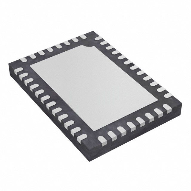
- Part No.:
- TDP142RNQT
- Manufacturer:
- Texas Instruments
- Category:
- Specialized
- Package:
- 40-WFQFN Exposed Pad
- Datasheet:
-
 TDP142RNQT.pdf
- Description:
- IC INTERFACE SPECIALIZED 40WQFN
- Quantity:
- Payment:

- Shipping:

Inventory:2,512
Please send an inquiry. Send us your inquiry, and we will respond immediately.
Product details
Overview
TDP142RNQT from Texas Instruments is a DisplayPort 1.4 linear redriver IC supporting 4-lane HBR3 operation at 8.1 Gbps per lane, featuring up to 14 dB receiver equalization, AUX/HPD signal snooping capability, and transparent link training compliance. It operates on a single 3.3 V supply and targets commercial temperature range (0°C to 70°C) in a 40-pin WQFN package.
For engineers reviewing the TDP142RNQT datasheet, TDP142RNQT pinout, TDP142RNQT application, or TDP142RNQT equivalent, this page delivers verified technical context, validated pin functions, real-world use cases in DP source/sink/cable positions, and confirmed alternative redrivers for DisplayPort 1.4 system design.
Technical Context
The TDP142RNQT implements a position-independent linear redriver architecture with per-lane differential input/output pairs (INDP0–3p/n, OUTDP0–3p/n), integrated AUX channel snooping (AUXp/n, HPDIN, SNOOPENZ), and dual-mode configuration via GPIO (DPEQ[1:0], I2C_EN, DPEN) or I²C (SCL/SDA). Its 4-level input logic enables 16 discrete equalization settings up to 14 dB at 4.05 GHz.
It supports native DisplayPort 1.4 HBR3 signaling while maintaining full transparency to link training, dynamically managing lane activation based on DPCD writes to LANE_COUNT_SET (0x00101) and SET_POWER_STATE (0x00600). Power delivery is optimized for ultra-low active consumption (660 mW at 4-lane 8.1 Gbps) and sub-1 mW shutdown mode.
Key Specifications
| Parameter | Value and Actual Design Meaning |
|---|---|
| Data Rate | 8.1 Gbps per lane (HBR3), compliant with VESA DisplayPort 1.4 standard. |
| Equalization Gain | Up to 14 dB at 4.05 GHz, selectable via GPIO or I²C for precise channel loss compensation. |
| Supply Voltage | 3.3 V ±10% (3.0–3.6 V), single-rail operation with 100 ms ramp requirement. |
| Power Consumption | 660 mW typical active (4-lane DP), 0.85 mW shutdown, enabling thermal-constrained designs. |
| Operating Temperature | 0°C to 70°C (commercial grade), validated across full range per JEDEC JESD22-A104. |
| Differential Impedance | 75–120 Ω transmitter output impedance, matched to DisplayPort 1.4 channel requirements. |
| Jitter Performance | 0.08 UIpp deterministic jitter and 0.135 UIpp total jitter at 8.1 Gbps (PRBS7). |
Pinout & Package
Package: 40-pin WQFN (RNQ), 4.0 mm × 6.0 mm body, 0.4 mm pitch, exposed thermal pad (GND).
| Pin/Terminal | Circuit Role | Design Meaning |
|---|---|---|
| VCC (pins 1,6,20,28) | Power Supply Input | 3.3 V main supply; four dedicated pins reduce IR drop and improve PSRR. |
| INDP0p/n – INDP3p/n (pins 9–10,12–13,15–16,18–19) | Differential Data Input | Four bidirectional DP lane inputs; support AC-coupled traces and internal 80–120 Ω termination. |
| OUTDP0p/n – OUTDP3p/n (pins 39–40,36–37,33–34,30–31) | Differential Data Output | Four lane outputs with 1500 mVPP swing, 75–120 Ω differential impedance, and <40 ps rise/fall time. |
| AUXp/n (pins 24–25) | AUX Channel Interface | CMOS I/O pair for snooping native AUX traffic between source and sink without protocol interruption. |
| HPDIN/RSVD9 (pin 32), DPEN/HPDIN (pin 23) | Hot-Plug Detect Input | Failsafe inputs detecting sink presence; trigger lane disable if low >2 ms (per VESA spec). |
| SNOOPENZ/RSVD8 (pin 29) | AUX Snooping Control | GPIO-controlled enable/disable of AUX snooping; high = snoop disabled, all lanes active. |
| I2C_EN (pin 17), TEST1/SCL (21), TEST2/SDA (22) | I²C Configuration Interface | Selects I²C mode (1, R, F) or GPIO mode (0); supports FM+ (1 MHz) and FM (400 kHz) bus speeds. |
| DPEQ0/A1 (14), DPEQ1 (2), A0 (11) | Equalization & Address Control | 4-level GPIOs setting EQ gain (16 options) and defining I²C slave address (7-bit, 16 possible values). |
Key Features
| Feature | Design Value |
|---|---|
| Position-Independent Redriving | Operates identically in source, cable, or sink location without firmware or configuration changes. |
| Native AUX Snooping | Monitors DPCD register writes (0x00101, 0x00600) to auto-manage lane count and power state-no host CPU intervention required. |
| Transparent Link Training | No modification to DP link training sequence; preserves native eye diagram, clock recovery, and error handling behavior. |
| Ultra-Low-Power Architecture | Sub-1 mW shutdown current and 660 mW active power enable fanless tablets, docks, and thin clients. |
| Dual-Mode Configuration | Hardware-selectable GPIO mode (I2C_EN = 0) or I²C mode (I2C_EN ≠ 0) with identical functional coverage. |
Applications
| DisplayPort Source Integration | Active Cable Assembly |
|---|---|
Use Scenario: Embedded GPU output extension in ultrabooks and 2-in-1 laptops where PCB trace loss exceeds 12 dB at 4.05 GHz. IC Role / Device Role / Timing Role: Linear redriver placed between GPU PHY and edge connector; recovers signal integrity without altering link training timing. Use Value: Enables 8.1 Gbps DP 1.4 compliance over 12-inch FR4 traces, eliminating need for costly backplane redesign. |
Use Scenario: High-bandwidth passive-to-active cable conversion for VR headsets requiring 4K@120Hz over 2-meter lengths. IC Role / Device Role / Timing Role: Redriver embedded in cable plug housing; compensates for connector and cable insertion loss while preserving AUX handshake latency. Use Value: Achieves >14 dB equalization margin at 8.1 Gbps, supporting HDMI 2.0b dual-mode operation via AC coupling. |
| Monitor Input Re-timer | Docking Station Signal Aggregation |
Use Scenario: Entry-level 4K monitor receiving DP 1.4 signals from diverse laptop models with varying PHY drive strength. IC Role / Device Role / Timing Role: Sink-side redriver restoring signal amplitude and jitter margin before display controller deserializer. Use Value: Eliminates display flicker and link training failures caused by marginal source output, improving out-of-box compatibility. |
Use Scenario: Multi-port docking station aggregating DP, USB-C, and HDMI outputs from a single laptop upstream port. IC Role / Device Role / Timing Role: Redriver isolating and conditioning DP lanes prior to multiplexer switching and ESD protection stages. Use Value: Maintains HBR3 eye opening across all downstream ports despite shared PCB routing and crosstalk. |
Equivalent & Alternatives
The following parts are listed as comparable options for similar DisplayPort redriver applications.
| Alternative Part | Technical Difference | Application Difference | Selection Advice |
|---|---|---|---|
| TI TDP140RNQT | Supports HBR2 only (5.4 Gbps), 12 dB max EQ, no AUX snooping, same WQFN-40 package. | Limited to DP 1.2 systems; cannot handle 4K@120Hz or DSC-enabled streams. | Select when cost sensitivity outweighs HBR3 requirement and AUX-aware lane management is unnecessary. |
| Diodes AP142BQF-13 | Same 8.1 Gbps HBR3 support and 14 dB EQ, but lacks AUX snooping and uses different I²C addressing scheme. | Requires external logic for lane count adaptation; no native DPCD register monitoring. | Choose for legacy designs already using Diodes' AP142 family; verify I²C register map compatibility before substitution. |
Compared with TDP142RNQT, TDP140RNQT trades bandwidth and intelligence for lower cost and power, while AP142BQF-13 matches speed but requires host-driven lane control-making TDP142RNQT the only option with autonomous AUX-based lane management at HBR3.
Availability
TDP142RNQT is available at Aetrix Electronics and suitable for active cable assemblies, docking stations, and DisplayPort source/sink designs requiring stable component supply, long-term lifecycle assurance, and guaranteed traceable sourcing.
Supply support for TDP142RNQT includes scheduled delivery planning, volume procurement assistance, BOM continuity management, traceable sourcing, and lifecycle availability coordination for OEM customers, industrial embedded developers, connected-device designers, and electronics production programs.
Manufacturer
Texas Instruments is a global semiconductor company headquartered in Dallas, Texas, delivering analog and embedded processing solutions for industrial, automotive, and personal electronics markets.
The TDP142RNQT belongs to TI's DisplayPort redriver product line, engineered specifically to extend reach and reliability of high-speed DP 1.4 links in thermally constrained, space-limited applications such as ultraportables and compact monitors.
FAQ
What is the maximum data rate supported by the TDP142RNQT?
The TDP142RNQT supports DisplayPort 1.4 High Bit Rate 3 (HBR3) operation at 8.1 Gbps per lane across all four lanes. This enables uncompressed 4K@120Hz or 8K@30Hz video transmission. The device maintains full compliance with VESA DP 1.4 specifications including link training transparency and AUX channel snooping at this rate. TDP142RNQT achieves this with up to 14 dB of linear equalization at 4.05 GHz.
Does the TDP142RNQT require firmware or host processor intervention to manage DisplayPort lanes?
No, the TDP142RNQT autonomously manages lane activation and power state without host firmware. It snoops native AUX writes to DPCD registers 0x00101 (LANE_COUNT_SET) and 0x00600 (SET_POWER_STATE), enabling or disabling lanes in real time. This behavior is intrinsic to the TDP142RNQT hardware and functions identically in GPIO or I²C configuration modes.
Can the TDP142RNQT be used in both source and sink positions within a DisplayPort chain?
Yes, the TDP142RNQT is explicitly designed as a position-independent linear redriver. Its transparent link training, symmetric input/output architecture, and AUX/HPD signal monitoring allow deployment between GPU and connector (source), inside active cables, or before display controller (sink) without reconfiguration. This flexibility is confirmed in the TDP142RNQT datasheet Section 3 and Functional Block Diagram.
What package type and thermal characteristics does the TDP142RNQT use?
The TDP142RNQT uses a 40-pin WQFN (RNQ) package measuring 4.0 mm × 6.0 mm with 0.4 mm pitch and an exposed thermal pad connected to GND. Its junction-to-board thermal resistance (RθJB) is 9.5°C/W, and junction-to-ambient (RθJA) is 37.6°C/W. These values are measured per JEDEC JESD51 standards and validate suitability for compact, fanless designs.
How does the TDP142RNQT handle power management during DisplayPort link idle states?
The TDP142RNQT supports electrical idle detection and enters low-power states automatically. When DPEN is deasserted or HPDIN drops low for >2 ms, all lanes disable with 0.85 mW shutdown current. During active idle (e.g., DP electrical idle mode), it maintains signal integrity with <10 mVpp differential output while consuming only 2.4 mW in no-connection state-both values specified in TDP142RNQT Section 6.5.
TDP142RNQT Specifications
- Product attributes
- Attribute value
- Manufacturer:
- Texas Instruments
- Series:
- DisplayPort™
- Package/Case:
- 40-WFQFN Exposed Pad
- Packaging:
- Tape & Reel (TR)
- Product Status:
- Active
- Applications:
- Personal Computers, CAD/CAM/CAE Workstation, Point-of-Sale Terminals, Audio/Visual Devices, Limited Space Areas
- Interface:
- HDMI
- Voltage - Supply:
- 3V ~ 3.6V
- Supplier Device Package:
- 40-WQFN (6x4)
- Grade:
- -
- Qualification:
- -
- Mounting Type:
- Surface Mount
TDP142RNQT FAQ
1.How can I place an order for TDP142RNQT through Aetrix?
Please submit a Request for Quotation (RFQ) for TDP142RNQT on Aetrix. Our sales agent will provide a competitive quotation and guide you through the order confirmation once you accept the terms.
2.Are the price and stock information for TDP142RNQT reliable?
The price and inventory of TDP142RNQT are updated periodically and may fluctuate due to market conditions. Stock and pricing data are typically refreshed every 24 hours. Quotation validity for TDP142RNQT is usually 5 days.
3.What payment methods are accepted for TDP142RNQT?
We accept Wire Transfer, PayPal, Credit Card, Western Union, MoneyGram, and Escrow for TDP142RNQT transactions.
Note: Certain payment methods may incur a processing fee.
4.How is shipping managed for TDP142RNQT?
TDP142RNQT orders can be shipped via leading logistics carriers, including DHL, UPS, FedEx, TNT, or Registered Mail.
Once your TDP142RNQT order is processed, you will receive an email with the shipment details and tracking number.
Note: Tracking information may take up to 24 hours to appear. Express delivery typically takes 3–5 business days.
5.How can I obtain technical support or documentation for TDP142RNQT?
For technical support, including TDP142RNQT datasheets, pinout diagrams, or application guidance, please contact our engineering support team. They can provide detailed documentation and assistance for your TDP142RNQT requirements.
6.How does Aetrix verify that TDP142RNQT is sourced from the original manufacturer or authorized distributors?
All TDP142RNQT products on Aetrix are procured from qualified distributors and authorized channels. Our dedicated quality assurance team conducts strict verification, including traceability checks and, if necessary, third-party testing. This ensures that TDP142RNQT meets industry standards.
7.What is the process for return or replacement of TDP142RNQT?
All TDP142RNQT units undergo pre-shipment inspection (PSI). If there is an issue with TDP142RNQT, returns or replacements are accepted under the following conditions:
1.Quantity discrepancies, incorrect items, or visible external defects (such as breakage or corrosion), acknowledged by Aetrix.
2.The issue is reported within 90 days of delivery.
3.The TDP142RNQT part is unused and in its original packaging.
Return procedure for TDP142RNQT:
1.Submit a request within 90 days.
2.Obtain a Return Material Authorization (RMA) from Aetrix.
TDP142RNQT Tags

-
NVT4857UKAZ
NXP Semiconductors

-
TCA8418RTWR
Texas Instruments

-
PCA9546APWR
Texas Instruments

-
MD0100N8-G
Microchip Technology

-
PCA9548APW,118
NXP Semiconductors

-
PCA9540BDP,118
NXP Semiconductors

-
PCA9548APWR
Texas Instruments

-
PCA9546APW,118
NXP Semiconductors

-
PTN3360DBS,518
NXP Semiconductors

-
PCA9546ABS,118
NXP Semiconductors

-
PCA9518PWR
Texas Instruments

-
PCA9545APW,118
NXP Semiconductors
Tech Hub

A practical engineering guide to 3.3V and 5V logic compatibility, input thresholds, resistor dividers, translator ICs, MOSFET level shifting, I2C pull-ups, timing limits and power-sequencing risks.

The 74HC595 uses push-pull logic outputs, while the TPIC6B595 uses 50 V open-drain DMOS sinks for higher-power loads. This guide compares timing, current limits, 3.3 V interfacing, load wiring, thermal…

The 74HC595 converts serial data into eight stable parallel outputs. This guide covers pin functions, shift and storage timing, OE and MR behavior, drive-current limits, cascading, voltage compatibilit…

A technical comparison of level-sensitive latches and edge-triggered flip-flops, covering timing windows, setup and hold limits, master–slave operation, time borrowing, race-through, HDL inference and…

A D latch stores one bit while Enable controls when data can pass. This reference covers gate-level operation, truth tables, transparency, setup and hold timing, LE versus OE, common ICs and practical …

An SR latch stores one bit through cross-coupled feedback. This engineering reference covers NOR and NAND implementations, truth tables, forbidden-state recovery, gated operation, switch debouncing, fa…

Latch circuits retain one bit through feedback. This technical reference covers SR and D latches, truth tables, transparency, timing limits, latch-versus-flip-flop behavior, applications and common log…

An engineering guide to LED driver operation, constant-current and constant-voltage outputs, linear and switching topologies, dimming, IC selection, calculations, replacement compatibility, and fault c…

Operational amplifier guide covering op amp basics, feedback, ideal vs real op amps, common configurations, buffer circuits, offset, bias current, gain-bandwidth, slew rate, rail-to-rail limits and sel…

Jumper cables guide covering safe connection order, red and black clamp placement, final ground connection, cable gauge, length, clamp quality, copper vs CCA cables, jump starter comparison and battery…


