
 My Inquiry
 My Account


NXP Semiconductors TEA1762T/N2,118
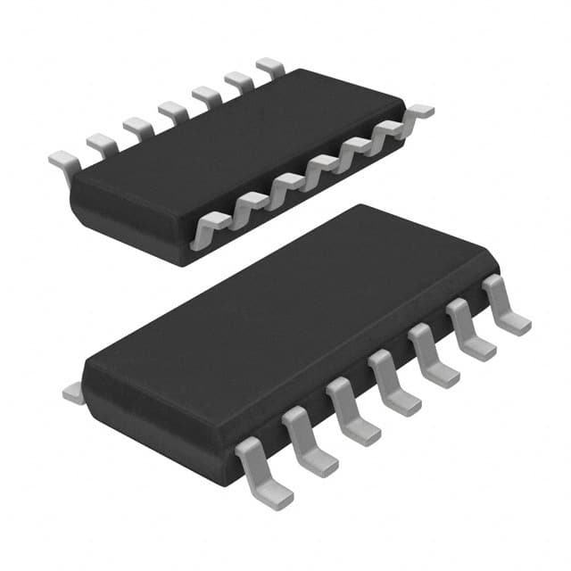
- Part No.:
- TEA1762T/N2,118
- Manufacturer:
- NXP Semiconductors
- Category:
- Power Supply Controllers, Monitors
- Package:
- 14-SOIC (0.154", 3.90mm Width)
- Datasheet:
-
 TEA1762T/N2,118.pdf
- Description:
- IC CTRLR GREENCHIP SYNC 14-SOIC
- Quantity:
- Payment:

- Shipping:

Inventory:3,272
Please send an inquiry. Send us your inquiry, and we will respond immediately.
Product details
Overview
TEA1762T/N2,118 from NXP Semiconductors is a synchronous rectifier (SR) controller IC for discontinuous conduction mode (DCM) and quasi-resonant flyback converters. It integrates SR timing, output voltage regulation (2.5 V reference), output current limiting (50 mV threshold), 10 V gate driver, and dual opto-coupler outputs (OPTOREG/OPTOPROT) in a single SO14 package-enabling high-efficiency, low-component-count AC/DC adapters.
For engineers reviewing the TEA1762T/N2,118 datasheet, TEA1762T/N2,118 pinout, TEA1762T/N2,118 application, or TEA1762T/N2,118 equivalent, this page delivers verified technical context, real-world design meaning of key specs, validated pin functions, and two confirmed alternative parts with precise functional and application-level differences.
Technical Context
The TEA1762T/N2,118 implements zero-current-switching (ZCS) synchronous rectification via three-stage SRSENSE sensing: activation at −310 mV, regulation at −55 mV, and deactivation at −12 mV-ensuring fast MOSFET turn-off at current zero crossing. Its dual feedback architecture uses VSENSE (2.5 V regulated) for voltage control and ISENSE (50 mV regulated) for current limiting, both referenced to separate ground pins (SENSEGND and POWERGND) to minimize sensing error.
It features integrated overtemperature protection (150 °C typical trip), undervoltage lockout (8.6 V start-up, 0.5 V hysteresis), and two open-drain opto outputs with 5 mA sink capability-each linearly controlled by VSENSE or ISENSE to drive primary-side controllers. The 10 V driver supports fast switching (250 mA source / 2.7 A sink) across all MOSFET brands.
Key Specifications
| Parameter | Value and Actual Design Meaning |
|---|---|
| VCC Range | 8.6 V to 38 V - enables direct operation from wide-range auxiliary windings without external LDO |
| SRSENSE Thresholds | −310 mV (activate), −55 mV (regulate), −12 mV (deactivate) - enables precise ZCS detection and eliminates need for standby mode |
| VSENSE Regulation | 2.5 V ±1 % - provides accurate secondary-side voltage feedback for <±1% output regulation |
| ISENSE Regulation | 50 mV ±4 mV - sets precise constant-current limit without external op-amp or shunt calibration |
| Driver Output | 10 V max, 250 mA source / 2.7 A sink - drives low-RDS(on) MOSFETs fully on with minimal conduction loss |
| Opto Output Sink | 5 mA typical - directly interfaces with standard opto-couplers (e.g., PC817, LTV-817) without external pull-up resistors |
| OTP Trip Temp | 150 °C typical - triggers OPTOPROT output to shut down primary controller before thermal runaway |
Pinout & Package
TEA1762T/N2,118 is housed in a plastic small outline package (SO14), SOT108-1, with 14 leads and 3.9 mm body width. Thermal resistance is 100 K/W in free air.
| Pin/Terminal | Circuit Role | Design Meaning |
|---|---|---|
| 1 SRSENSE | Synchronous rectification timing input | Detects secondary winding polarity reversal to trigger MOSFET turn-on; blanked for 2 µs after activation to suppress ringing-induced false turn-off |
| 2 POWERGND | Power ground reference | Return path for DRIVER, ISENSE, and OPTO outputs; separates high-current return from precision sensing |
| 3 SENSEGND | Sense ground reference | Reference for VSENSE and internal bandgap; enables cable-drop compensation and improves voltage regulation accuracy |
| 4 PROTECT | General-purpose protection input | Accepts NTC or Zener-based signals for external overtemperature or overvoltage protection; 1.25 V threshold with 30 mV hysteresis |
| 5, 12, 13 n.c. | No connection | Unbonded pins-must remain unconnected per layout guidelines |
| 6 DRIVER | SR MOSFET gate driver output | 10 V push-pull output capable of 2.7 A sink to rapidly discharge MOSFET gate and ensure hard turn-off at zero current |
| 7 OPTOPROT | Opto-coupler driver for current/fault protection | Open-drain output sinking up to 5 mA; activated during OTP or ISENSE over-limit to signal primary-side shutdown |
| 8 OPTOREG | Opto-coupler driver for voltage regulation | Open-drain output sinking up to 5 mA; linearly controlled by VSENSE to maintain stable output voltage under load transients |
| 9 VREF | 2.5 V reference voltage output | Stable, trimmed 2.5 V supply (±1%) for external circuitry; limited to 1 mA load to preserve accuracy |
| 10 VSENSE | Voltage sense input | Regulated to 2.5 V w.r.t. SENSEGND; connects to resistor divider from output to set precise voltage setpoint |
| 11 ISENSE | Current sense input | Regulated to 50 mV w.r.t. POWERGND; connects to current-sense resistor to implement CC/CV charging or OCP |
| 14 VCC | Supply voltage input | Accepts 8.6–38 V; powers internal circuitry and enables UVLO with 0.5 V hysteresis for reliable start-up |
Key Features
| Feature | Design Value |
|---|---|
| Integrated SR + Primary Feedback Control | Eliminates need for separate voltage/current sense ICs and opto interface logic-reducing BOM count by ≥4 components |
| Separate Sense Ground (SENSEGND) | Enables ±0.5% output voltage accuracy under load and supports remote sensing for USB-C PD or laptop adapter cable compensation |
| Zero-Current Switching (ZCS) Logic | Reduces reverse recovery losses in secondary-side MOSFETs and maintains >90% efficiency from 10% to full load without burst-mode complexity |
| 10 V Gate Driver | Ensures full enhancement of modern low-threshold GaN and SiC FETs, achieving RDS(on) utilization within 5% of datasheet minimum |
| Internal 1% Voltage Reference | Removes need for external precision reference IC or trimming resistors-simplifying layout and improving long-term stability |
Applications
| USB-C Power Adapter | Laptop AC/DC Adapter |
|---|---|
Use Scenario: 45 W–65 W USB-C PD adapter using QR flyback topology with GaN primary switch and Si MOSFET secondary rectifier. IC Role / Device Role / Timing Role: TEA1762T/N2,118 controls synchronous rectification timing, regulates 20 V output voltage via VSENSE, and limits output current to 3.25 A via ISENSE-communicating both parameters to primary controller through dual opto outputs. Use Value: Achieves >93% peak efficiency and meets DOE VI/CoC Tier 2 requirements without auxiliary winding or complex digital control. | Use Scenario: 90 W universal laptop adapter supporting 15–20 V output with adaptive voltage/current profiles. IC Role / Device Role / Timing Role: TEA1762T/N2,118 serves as the secondary-side regulator and protector-using SENSEGND for cable-drop compensation and PROTECT pin for NTC-based transformer overtemperature monitoring. Use Value: Enables single-board design across multiple output voltages while maintaining ±1% load regulation and thermal safety compliance. |
| Industrial AC/DC Power Supply | Medical Grade Wall Adapter |
Use Scenario: 36 W industrial power module for PLC I/O modules requiring high reliability and wide input range. IC Role / Device Role / Timing Role: TEA1762T/N2,118 manages synchronous rectification and provides redundant overcurrent protection via ISENSE and PROTECT pins-feeding fault signals to primary controller for graceful shutdown. Use Value: Reduces heat generation in enclosed enclosures and extends MTBF by eliminating diode conduction losses. | Use Scenario: 15 W Class II medical wall adapter (IEC 60601-1) powering patient-monitoring peripherals. IC Role / Device Role / Timing Role: TEA1762T/N2,118 implements isolated voltage/current regulation and OTP using OPTOREG/OPTOPROT outputs-ensuring no single-point failure compromises isolation barrier integrity. Use Value: Meets creepage/clearance requirements with minimal component count and avoids reliance on external analog comparators. |
Equivalent & Alternatives
The following parts are listed as comparable options for similar synchronous rectifier controller applications.
| Alternative Part | Technical Difference | Application Difference | Selection Advice |
|---|---|---|---|
| ON Semiconductor NCP4303DR2G | Single opto output (voltage only); no integrated current regulation; requires external current sense amplifier | Supports only voltage-regulated flyback designs; unsuitable for CC/CV battery chargers or multi-output supplies | Select when cost sensitivity outweighs need for dual-loop control and system-level current limiting is handled on primary side |
| Infineon IRS27952SPBF | Higher VCC range (12–40 V); no internal voltage reference; uses external 2.5 V reference; no PROTECT pin | Requires additional reference IC and external protection circuitry; better suited for high-voltage industrial SMPS than compact adapters | Select when operating above 38 V or when existing design already includes precision reference and discrete protection |
Compared with NCP4303DR2G and IRS27952SPBF, TEA1762T/N2,118 uniquely integrates dual-loop (V/I) regulation, dedicated sense ground, and a general-purpose protection input-making it the only option among the three that supports self-contained CC/CV adapter designs without external support components.
Availability
TEA1762T/N2,118 is available at Aetrix Electronics and suitable for USB-C PD adapters, laptop AC/DC adapters, and industrial AC/DC power supplies requiring stable component supply, long-lifecycle support, and consistent parametric performance across production batches.
Supply support for TEA1762T/N2,118 includes scheduled delivery planning, volume procurement assistance, BOM continuity management, traceable sourcing, and lifecycle availability coordination for OEM customers, industrial embedded developers, connected-device designers, and electronics production programs.
Manufacturer
NXP Semiconductors is a global semiconductor company headquartered in Eindhoven, Netherlands, specializing in secure connectivity solutions for automotive, industrial, and consumer applications.
The TEA1762T/N2,118 belongs to NXP's GreenChip family-designed specifically for high-efficiency, low-standby-power AC/DC conversion in compact, cost-sensitive power adapters and chargers.
FAQ
What is the function of the SENSEGND pin on the TEA1762T/N2,118?
The SENSEGND pin on the TEA1762T/N2,118 serves as the dedicated reference for the VSENSE input and internal voltage reference, enabling accurate output voltage regulation even under varying load conditions. It is internally isolated from POWERGND via anti-parallel diodes to prevent noise coupling. In practice, connecting SENSEGND to the low-side of the output voltage divider-rather than to POWERGND-compensates for PCB trace resistance and improves load regulation to within ±0.5%, which is critical for USB-C PD and laptop adapter designs.
How does the TEA1762T/N2,118 achieve zero-current switching (ZCS) for synchronous rectification?
The TEA1762T/N2,118 achieves ZCS by monitoring the SRSENSE pin for three precise voltage thresholds: it activates the DRIVER output at −310 mV (indicating secondary current flow start), regulates the output to hold −55 mV during conduction, then deactivates at −12 mV-corresponding to zero secondary current crossing. This sequence, combined with 2 µs blanking after activation, ensures the external MOSFET turns off exactly when current reaches zero, eliminating reverse-recovery losses and enabling high efficiency across light to full load without burst mode.
Can the TEA1762T/N2,118 be used in continuous conduction mode (CCM) flyback converters?
No, the TEA1762T/N2,118 is explicitly designed for discontinuous conduction mode (DCM) and quasi-resonant (QR) flyback topologies only. Its SRSENSE timing logic, blanking window, and driver activation/deactivation thresholds assume a clear zero-current interval between switching cycles. In CCM operation, the absence of a natural current-zero crossing prevents reliable ZCS detection, leading to shoot-through risk and potential MOSFET failure. NXP documentation confirms DCM/QR use only.
What is the maximum allowable voltage on the VSENSE pin of the TEA1762T/N2,118?
The maximum allowable voltage on the VSENSE pin of the TEA1762T/N2,118 is +5 V relative to SENSEGND, as specified in the Absolute Maximum Ratings table. Exceeding this voltage-even momentarily-may damage the internal transconductance amplifier or bandgap reference. In normal operation, VSENSE is regulated to 2.5 V; designers must ensure the feedback resistor divider never pulls VSENSE above 5 V during startup, transient overload, or open-loop conditions.
Does the TEA1762T/N2,118 support programmable overtemperature protection?
No, the TEA1762T/N2,118 features fixed internal overtemperature protection with a typical trip point of 150 °C and 12 °C hysteresis-no external programming or adjustment is possible. When triggered, it maximizes sink current on the OPTOPROT pin to signal the primary-side controller. For designs requiring custom temperature thresholds, the PROTECT pin can be used with an external NTC thermistor network to provide adjustable overtemperature response independent of the internal OTP circuit.
TEA1762T/N2,118 Specifications
- Product attributes
- Attribute value
- Manufacturer:
- NXP Semiconductors
- Series:
- GreenChip™
- Package/Case:
- 14-SOIC (0.154", 3.90mm Width)
- Packaging:
- Tape & Reel (TR)
- Product Status:
- Obsolete
- Programmable:
- Not Verified
- Applications:
- Secondary-Side Controller
- Voltage - Input:
- -
- Voltage - Supply:
- 8.6V ~ 38V
- Current - Supply:
- 1 mA
- Operating Temperature:
- -20°C ~ 150°C
- Grade:
- -
- Qualification:
- -
- Mounting Type:
- Surface Mount
- Supplier Device Package:
- 14-SO
TEA1762T/N2,118 FAQ
1.How can I place an order for TEA1762T/N2,118 through Aetrix?
Please submit a Request for Quotation (RFQ) for TEA1762T/N2,118 on Aetrix. Our sales agent will provide a competitive quotation and guide you through the order confirmation once you accept the terms.
2.Are the price and stock information for TEA1762T/N2,118 reliable?
The price and inventory of TEA1762T/N2,118 are updated periodically and may fluctuate due to market conditions. Stock and pricing data are typically refreshed every 24 hours. Quotation validity for TEA1762T/N2,118 is usually 5 days.
3.What payment methods are accepted for TEA1762T/N2,118?
We accept Wire Transfer, PayPal, Credit Card, Western Union, MoneyGram, and Escrow for TEA1762T/N2,118 transactions.
Note: Certain payment methods may incur a processing fee.
4.How is shipping managed for TEA1762T/N2,118?
TEA1762T/N2,118 orders can be shipped via leading logistics carriers, including DHL, UPS, FedEx, TNT, or Registered Mail.
Once your TEA1762T/N2,118 order is processed, you will receive an email with the shipment details and tracking number.
Note: Tracking information may take up to 24 hours to appear. Express delivery typically takes 3–5 business days.
5.How can I obtain technical support or documentation for TEA1762T/N2,118?
For technical support, including TEA1762T/N2,118 datasheets, pinout diagrams, or application guidance, please contact our engineering support team. They can provide detailed documentation and assistance for your TEA1762T/N2,118 requirements.
6.How does Aetrix verify that TEA1762T/N2,118 is sourced from the original manufacturer or authorized distributors?
All TEA1762T/N2,118 products on Aetrix are procured from qualified distributors and authorized channels. Our dedicated quality assurance team conducts strict verification, including traceability checks and, if necessary, third-party testing. This ensures that TEA1762T/N2,118 meets industry standards.
7.What is the process for return or replacement of TEA1762T/N2,118?
All TEA1762T/N2,118 units undergo pre-shipment inspection (PSI). If there is an issue with TEA1762T/N2,118, returns or replacements are accepted under the following conditions:
1.Quantity discrepancies, incorrect items, or visible external defects (such as breakage or corrosion), acknowledged by Aetrix.
2.The issue is reported within 90 days of delivery.
3.The TEA1762T/N2,118 part is unused and in its original packaging.
Return procedure for TEA1762T/N2,118:
1.Submit a request within 90 days.
2.Obtain a Return Material Authorization (RMA) from Aetrix.
TEA1762T/N2,118 Tags

-
UC3845AD8TR
Texas Instruments
-
UC2843AD8TR
Texas Instruments

-
LM3880MFX-1AE/NOPB
Texas Instruments
-
LM3880MFX-1AA/NOPB
Texas Instruments

-
INA234AIYBJR
Texas Instruments

-
INA700AYWFR
Texas Instruments
-
LM3880MF-1AE/NOPB
Texas Instruments
-
LM3880MF-1AA/NOPB
Texas Instruments

-
LM3881MM/NOPB
Texas Instruments
-
UCC2802DTR
Texas Instruments

-
NCP4305DMTTWG
onsemi

-
INA237AIDGSR
Texas Instruments
Tech Hub

A practical engineering guide to 3.3V and 5V logic compatibility, input thresholds, resistor dividers, translator ICs, MOSFET level shifting, I2C pull-ups, timing limits and power-sequencing risks.

The 74HC595 uses push-pull logic outputs, while the TPIC6B595 uses 50 V open-drain DMOS sinks for higher-power loads. This guide compares timing, current limits, 3.3 V interfacing, load wiring, thermal…

The 74HC595 converts serial data into eight stable parallel outputs. This guide covers pin functions, shift and storage timing, OE and MR behavior, drive-current limits, cascading, voltage compatibilit…

A technical comparison of level-sensitive latches and edge-triggered flip-flops, covering timing windows, setup and hold limits, master–slave operation, time borrowing, race-through, HDL inference and…

A D latch stores one bit while Enable controls when data can pass. This reference covers gate-level operation, truth tables, transparency, setup and hold timing, LE versus OE, common ICs and practical …

An SR latch stores one bit through cross-coupled feedback. This engineering reference covers NOR and NAND implementations, truth tables, forbidden-state recovery, gated operation, switch debouncing, fa…

Latch circuits retain one bit through feedback. This technical reference covers SR and D latches, truth tables, transparency, timing limits, latch-versus-flip-flop behavior, applications and common log…

An engineering guide to LED driver operation, constant-current and constant-voltage outputs, linear and switching topologies, dimming, IC selection, calculations, replacement compatibility, and fault c…

Operational amplifier guide covering op amp basics, feedback, ideal vs real op amps, common configurations, buffer circuits, offset, bias current, gain-bandwidth, slew rate, rail-to-rail limits and sel…

Jumper cables guide covering safe connection order, red and black clamp placement, final ground connection, cable gauge, length, clamp quality, copper vs CCA cables, jump starter comparison and battery…


