
 My Inquiry
 My Account


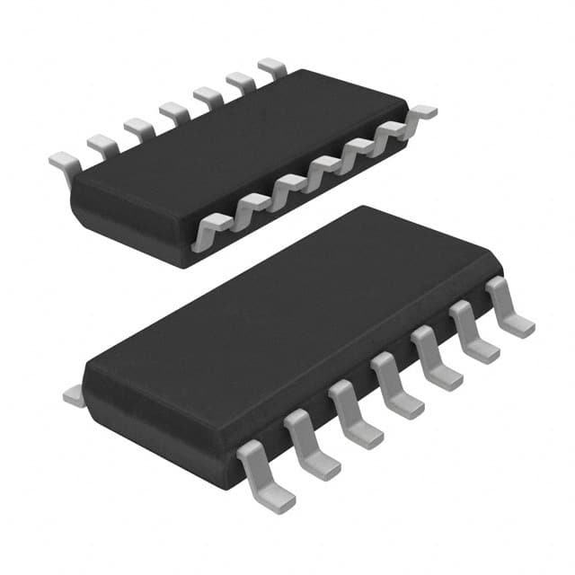
NXP Semiconductors TJA1041T/CM,118
- Part No.:
- TJA1041T/CM,118
- Manufacturer:
- NXP Semiconductors
- Category:
- Drivers, Receivers, Transceivers
- Package:
- 14-SOIC (0.154", 3.90mm Width)
- Datasheet:
-
 TJA1041T/CM,118.pdf
- Description:
- IC TRANSCEIVER HALF 1/1 14SO
- Quantity:
- Payment:

- Shipping:

Inventory:4,758
Please send an inquiry. Send us your inquiry, and we will respond immediately.
Product details
Overview
TJA1041T/CM,118 from NXP Semiconductors is a high-speed CAN transceiver designed for automotive network nodes, providing ISO 11898-compliant differential transmit/receive capability up to 1 Mbit/s, with VCC = 4.75–5.25 V, VI/O = 2.8–5.25 V, and VBAT = 5–27 V operation. It enables bidirectional communication between microcontroller protocol controllers and the physical CAN bus in body control modules, powertrain gateways, and ADAS domain controllers.
For engineers reviewing the TJA1041T/CM,118 datasheet, TJA1041T/CM,118 pinout, TJA1041T/CM,118 application, or TJA1041T/CM,118 equivalent, key selection criteria include its integrated wake-up source recognition, recessive bus DC stabilization via SPLIT pin, listen-only mode for failure containment, undervoltage detection on VCC/VI/O/VBAT, and passive behavior when supply is off.
Technical Context
The TJA1041T/CM,118 implements a five-mode operating architecture (Normal, pwon/listen-only, Standby, go-to-sleep command, Sleep) controlled by STB and EN pins, with internal flags (UVNOM, UVBAT, pwon, wake-up, bus failure, local failure, wake-up source) accessible via ERR pin. Its differential receiver features ±12 V common-mode range and 70 mV typical hysteresis, ensuring robust EMI immunity in noisy automotive environments.
It integrates TXD dominant clamping, RXD recessive clamping, TXD-to-RXD short-circuit, bus dominant clamping, and overtemperature protection - all triggering local failure flag assertion and transmitter disablement. The I/O-level adapter scales TXD/STB/EN thresholds and RXD/ERR output levels to match controller VI/O voltage (2.8–5.25 V), eliminating level-shifting components.
Key Specifications
| Parameter | Value and Actual Design Meaning |
|---|---|
| Bus Data Rate | Up to 1 Mbit/s - supports full-speed CAN FD pre-qualification and legacy CAN 2.0B networks. |
| VCC Operating Range | 4.75 V to 5.25 V - ensures stable operation across automotive battery fluctuations including cold-crank conditions. |
| VI/O Voltage Range | 2.8 V to 5.25 V - enables direct interface with 3.3 V and 5 V microcontrollers without external level shifters. |
| VBAT Operating Range | 5 V to 27 V - accommodates 12 V and 24 V vehicle architectures, including load dump transients up to 40 V. |
| Propagation Delay (TXD→RXD) | 40 ns to 255 ns - guarantees deterministic timing for real-time CAN arbitration and error handling. |
| Common-Mode Input Range | −12 V to +12 V - provides immunity against ground offset and noise in distributed vehicle networks. |
| ESD Robustness (CANH/L/SPLIT) | ±6 kV HBM - meets stringent automotive EMC requirements per ISO 10605. |
Pinout & Package
Package: SO14 (SOT108-1), plastic small outline, 14-lead, 3.9 mm body width, surface-mount compatible.
| Pin/Terminal | Circuit Role | Design Meaning |
|---|---|---|
| TXD (1) | Transmit data input | Digital input from controller; threshold adapts to VI/O voltage for 3.3 V/5 V compatibility. |
| GND (2) | Ground reference | Primary signal return path; decoupling capacitor placement critical for EMI suppression. |
| VCC (3) | Transceiver supply | 5 V nominal supply; undervoltage detection triggers Sleep mode if <3.3 V for >10 ms. |
| RXD (4) | Receive data output | Controller-facing digital output; voltage level tracks VI/O for seamless logic interfacing. |
| VI/O (5) | I/O-level adapter reference | Sets input thresholds and output drive levels; must be connected to controller's I/O supply rail. |
| EN (6) | Enable control input | Active-HIGH; used with STB to select Normal, Standby, or go-to-sleep command modes. |
| INH (7) | Inhibit output | Open-drain active-HIGH output; controls external voltage regulators to power-down node peripherals. |
| ERR (8) | Error/power-on indication | Active-LOW open-drain output; signals UVNOM, UVBAT, pwon, wake-up, bus/local failure flags. |
| WAKE (9) | Local wake-up input | Dual-edge sensitive; detects LOW→HIGH or HIGH→LOW transitions for flexible wake-up circuit design. |
| VBAT (10) | Battery voltage input | Direct connection to vehicle battery; powers internal bias circuits and enables wake-up during sleep. |
| SPLIT (11) | Common-mode stabilization | Provides 0.5×VCC in Normal/pwon modes; reduces EME by stabilizing recessive bus voltage. |
| CANL (12) | CAN bus low line | Differential bus terminal; rated for −27 V to +40 V; short-circuit proof to battery and ground. |
| CANH (13) | CAN bus high line | Differential bus terminal; complements CANL; supports >110-node networks with matched output voltage. |
| STB (14) | Standby control input | Active-LOW; primary control for entering Standby/Sleep modes and initiating wake-up sequences. |
Key Features
| Feature | Design Value |
|---|---|
| ISO 11898-2 compliance | Fully compliant physical layer implementation enabling drop-in replacement in certified automotive CAN designs. |
| Listen-only mode | Disables transmitter while retaining full receive capability - isolates faulty nodes without disrupting bus traffic. |
| Recessive bus stabilization | SPLIT pin delivers regulated 0.5×VCC to split termination, reducing EME spikes during recessive-to-dominant transitions. |
| Wake-up source recognition | Distinguishes local (WAKE pin) vs. remote (bus activity) wake events - enables differentiated power management responses. |
| Integrated undervoltage detection | Independent monitoring of VCC, VI/O, and VBAT with configurable thresholds and flag-based diagnostics via ERR pin. |
| Five-stage power management | Supports Normal → pwon/listen-only → Standby → go-to-sleep command → Sleep transitions with controlled INH sequencing. |
Applications
| Body Control Module (BCM) | Powertrain Gateway |
|---|---|
Use Scenario: Centralized control of lighting, door locks, windows, and HVAC in modern vehicles. IC Role / Device Role / Timing Role: CAN transceiver bridging MCU to high-speed chassis CAN bus at 500 kbit/s–1 Mbit/s. Use Value: Enables fail-safe operation via local failure detection and automatic transmitter disablement during TXD clamping or bus shorts. |
Use Scenario: Aggregating and routing messages between engine, transmission, and chassis ECUs. IC Role / Device Role / Timing Role: High-integrity physical layer interface supporting simultaneous multi-bus communication. Use Value: Provides recessive bus stabilization and wide common-mode range to maintain signal integrity across long harness runs. |
| ADAS Domain Controller | Electric Vehicle Battery Management System (BMS) |
Use Scenario: Real-time sensor fusion and actuator coordination for lane-keeping, AEB, and adaptive cruise control. IC Role / Device Role / Timing Role: Low-latency CAN interface with <255 ns TXD→RXD propagation delay for time-critical message handling. Use Value: Supports listen-only mode for diagnostic monitoring without bus interference during system updates or fault recovery. |
Use Scenario: Communication between cell monitoring units, pack controllers, and vehicle gateway in 400 V/800 V EV platforms. IC Role / Device Role / Timing Role: Robust CAN PHY with 27 V bus fault tolerance and ±6 kV HBM ESD protection on CANH/CANL. Use Value: Ensures reliable operation under high-voltage transients and thermal stress, with overtemperature shutdown protecting output drivers. |
Equivalent & Alternatives
The following parts are listed as comparable options for similar high-speed CAN transceiver applications.
| Alternative Part | Technical Difference | Application Difference | Selection Advice |
|---|---|---|---|
| TCAN1042DRBR | Higher VBAT max (42 V vs. 27 V); no SPLIT pin; fixed 3.3 V/5 V I/O support (no VI/O adaptation) | Preferred for 42 V load-dump systems; lacks recessive bus stabilization and dual-edge wake-up | Select TCAN1042DRBR only when extended VBAT rating is required and SPLIT functionality is unused. |
| SN65HVD255DR | No integrated wake-up source recognition; no undervoltage detection on VI/O; no listen-only mode | Suitable for cost-sensitive non-automotive industrial CAN; lacks automotive-grade diagnostics and fail-safe modes | Choose SN65HVD255DR only for non-automotive applications where full ISO 11898-2 diagnostics are not mandated. |
Compared with TCAN1042DRBR and SN65HVD255DR, the TJA1041T/CM,118 uniquely combines VI/O-adaptive I/O levels, SPLIT-based EME reduction, and wake-up source identification - making it the only option qualified for ASIL-B-relevant automotive subsystems requiring comprehensive fault containment.
Availability
TJA1041T/CM,118 is available at Aetrix Electronics and suitable for automotive body electronics, powertrain gateways, ADAS domain controllers, and EV battery management systems requiring stable component supply, long-term lifecycle assurance, and AEC-Q100 Grade 1 qualification.
Supply support for TJA1041T/CM,118 includes scheduled delivery planning, volume procurement assistance, BOM continuity management, traceable sourcing, and lifecycle availability coordination for OEM customers, industrial embedded developers, connected-device designers, and electronics production programs.
Manufacturer
NXP Semiconductors is a global semiconductor leader specializing in secure connectivity solutions for automotive, industrial, and IoT applications, with deep expertise in automotive networking and functional safety.
The TJA1041T/CM,118 belongs to NXP's automotive CAN transceiver product line, engineered specifically for ASIL-B-compliant vehicle networks requiring robust EMC performance, ultra-low standby current (<10 µA), and advanced diagnostic coverage.
FAQ
What is the maximum bus data rate supported by the TJA1041T/CM,118?
The TJA1041T/CM,118 supports a maximum bus data rate of 1 Mbit/s, fully compliant with ISO 11898-2 high-speed CAN specifications. This enables use in demanding automotive applications such as powertrain gateways and ADAS domain controllers where deterministic latency and bandwidth are critical. The TJA1041T/CM,118 maintains signal integrity at this rate through matched dominant output voltages (VO(dom)(m) ≤ ±0.15 V) and low propagation delay variation (40–255 ns).
How does the TJA1041T/CM,118 handle undervoltage conditions on VCC and VI/O?
The TJA1041T/CM,118 monitors VCC and VI/O independently, triggering the UVNOM flag if either drops below its threshold (VCC <3.3 V or VI/O <1.5 V) for longer than 10 ms. Upon flag assertion, it enters Sleep mode to prevent bus disturbance and disable external regulators via floating INH. Recovery requires clearing UVNOM via pwon or wake-up event. The TJA1041T/CM,118 thus enforces fail-safe behavior without external supervision.
What is the function of the SPLIT pin on the TJA1041T/CM,118?
The SPLIT pin on the TJA1041T/CM,118 delivers a stabilized 0.5×VCC voltage during Normal and pwon/listen-only modes to enable split-termination networks. This reduces common-mode voltage steps during recessive-to-dominant transitions, lowering electromagnetic emissions (EME) in partially powered vehicle networks. In Standby and Sleep modes, SPLIT is set floating to minimize leakage. The TJA1041T/CM,118 is the only transceiver in its class offering this EME-optimized feature with built-in regulation.
Can the TJA1041T/CM,118 operate with a 3.3 V microcontroller I/O supply?
Yes, the TJA1041T/CM,118 supports VI/O from 2.8 V to 5.25 V, allowing direct interface with 3.3 V microcontrollers. Its integrated I/O-level adapter adjusts TXD/STB/EN input thresholds and RXD/ERR output voltage levels ratio-metrically to VI/O, eliminating external level shifters. When VI/O = 3.3 V, RXD outputs HIGH at ~2.9 V and LOW at <0.4 V, ensuring reliable logic interpretation by the host controller. This capability is intrinsic to the TJA1041T/CM,118 design.
What diagnostic capabilities does the ERR pin provide on the TJA1041T/CM,118?
The ERR pin on the TJA1041T/CM,118 is an active-LOW open-drain output that conveys five internal flags: UVNOM, UVBAT, pwon, wake-up, and bus/local failure. Each flag corresponds to a specific fault or state condition - e.g., UVNOM indicates VCC/VI/O undervoltage, wake-up signals local or remote activation, and bus failure detects CANH/CANL short circuits. These flags are accessed by monitoring ERR state transitions after mode changes, enabling real-time system diagnostics without additional hardware. The TJA1041T/CM,118 makes these diagnostics directly actionable via a single pin.
TJA1041T/CM,118 Specifications
- Product attributes
- Attribute value
- Manufacturer:
- NXP Semiconductors
- Series:
- -
- Package/Case:
- 14-SOIC (0.154", 3.90mm Width)
- Packaging:
- Tape & Reel (TR)
- Product Status:
- Active
- Type:
- Transceiver
- Protocol:
- CANbus
- Number of Drivers/Receivers:
- 1/1
- Duplex:
- Half
- Receiver Hysteresis:
- 70 mV
- Data Rate:
- -
- Voltage - Supply:
- 4.75V ~ 5.25V
- Operating Temperature:
- -
- Grade:
- -
- Qualification:
- -
- Mounting Type:
- Surface Mount
- Supplier Device Package:
- 14-SO
TJA1041T/CM,118 FAQ
1.How can I place an order for TJA1041T/CM,118 through Aetrix?
Please submit a Request for Quotation (RFQ) for TJA1041T/CM,118 on Aetrix. Our sales agent will provide a competitive quotation and guide you through the order confirmation once you accept the terms.
2.Are the price and stock information for TJA1041T/CM,118 reliable?
The price and inventory of TJA1041T/CM,118 are updated periodically and may fluctuate due to market conditions. Stock and pricing data are typically refreshed every 24 hours. Quotation validity for TJA1041T/CM,118 is usually 5 days.
3.What payment methods are accepted for TJA1041T/CM,118?
We accept Wire Transfer, PayPal, Credit Card, Western Union, MoneyGram, and Escrow for TJA1041T/CM,118 transactions.
Note: Certain payment methods may incur a processing fee.
4.How is shipping managed for TJA1041T/CM,118?
TJA1041T/CM,118 orders can be shipped via leading logistics carriers, including DHL, UPS, FedEx, TNT, or Registered Mail.
Once your TJA1041T/CM,118 order is processed, you will receive an email with the shipment details and tracking number.
Note: Tracking information may take up to 24 hours to appear. Express delivery typically takes 3–5 business days.
5.How can I obtain technical support or documentation for TJA1041T/CM,118?
For technical support, including TJA1041T/CM,118 datasheets, pinout diagrams, or application guidance, please contact our engineering support team. They can provide detailed documentation and assistance for your TJA1041T/CM,118 requirements.
6.How does Aetrix verify that TJA1041T/CM,118 is sourced from the original manufacturer or authorized distributors?
All TJA1041T/CM,118 products on Aetrix are procured from qualified distributors and authorized channels. Our dedicated quality assurance team conducts strict verification, including traceability checks and, if necessary, third-party testing. This ensures that TJA1041T/CM,118 meets industry standards.
7.What is the process for return or replacement of TJA1041T/CM,118?
All TJA1041T/CM,118 units undergo pre-shipment inspection (PSI). If there is an issue with TJA1041T/CM,118, returns or replacements are accepted under the following conditions:
1.Quantity discrepancies, incorrect items, or visible external defects (such as breakage or corrosion), acknowledged by Aetrix.
2.The issue is reported within 90 days of delivery.
3.The TJA1041T/CM,118 part is unused and in its original packaging.
Return procedure for TJA1041T/CM,118:
1.Submit a request within 90 days.
2.Obtain a Return Material Authorization (RMA) from Aetrix.
TJA1041T/CM,118 Tags

-
ATA6561-GAQW-N
Microchip Technology

-
ATA6561-GBQW-N
Microchip Technology

-
AM26LS32ACDR
Texas Instruments

-
SP485CN-L/TR
MaxLinear, Inc.
-
SP485EN-L/TR
MaxLinear, Inc.
-
SP485EEN-L/TR
MaxLinear, Inc.
-
SP485ECN-L/TR
MaxLinear, Inc.
-
THVD1400DR
Texas Instruments
-
AM26C31IDR
Texas Instruments

-
TLIN1021ADRQ1
Texas Instruments
-
MAX232IDR
Texas Instruments
-
AM26C32IDR
Texas Instruments
Tech Hub

A practical engineering guide to 3.3V and 5V logic compatibility, input thresholds, resistor dividers, translator ICs, MOSFET level shifting, I2C pull-ups, timing limits and power-sequencing risks.

The 74HC595 uses push-pull logic outputs, while the TPIC6B595 uses 50 V open-drain DMOS sinks for higher-power loads. This guide compares timing, current limits, 3.3 V interfacing, load wiring, thermal…

The 74HC595 converts serial data into eight stable parallel outputs. This guide covers pin functions, shift and storage timing, OE and MR behavior, drive-current limits, cascading, voltage compatibilit…

A technical comparison of level-sensitive latches and edge-triggered flip-flops, covering timing windows, setup and hold limits, master–slave operation, time borrowing, race-through, HDL inference and…

A D latch stores one bit while Enable controls when data can pass. This reference covers gate-level operation, truth tables, transparency, setup and hold timing, LE versus OE, common ICs and practical …

An SR latch stores one bit through cross-coupled feedback. This engineering reference covers NOR and NAND implementations, truth tables, forbidden-state recovery, gated operation, switch debouncing, fa…

Latch circuits retain one bit through feedback. This technical reference covers SR and D latches, truth tables, transparency, timing limits, latch-versus-flip-flop behavior, applications and common log…

An engineering guide to LED driver operation, constant-current and constant-voltage outputs, linear and switching topologies, dimming, IC selection, calculations, replacement compatibility, and fault c…

Operational amplifier guide covering op amp basics, feedback, ideal vs real op amps, common configurations, buffer circuits, offset, bias current, gain-bandwidth, slew rate, rail-to-rail limits and sel…

Jumper cables guide covering safe connection order, red and black clamp placement, final ground connection, cable gauge, length, clamp quality, copper vs CCA cables, jump starter comparison and battery…


