
 My Inquiry
 My Account


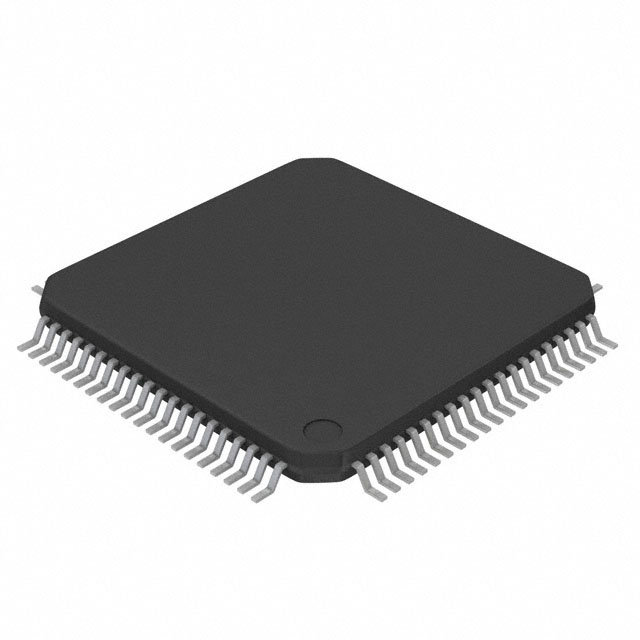
Texas Instruments TL16C554AIPNR
- Part No.:
- TL16C554AIPNR
- Manufacturer:
- Texas Instruments
- Package:
- 80-LQFP
- Datasheet:
-
 TL16C554AIPNR.pdf
- Description:
- IC ASYNC COMM ELEMENT 80-LQFP
- Quantity:
- Payment:

- Shipping:

Inventory:432
Please send an inquiry. Send us your inquiry, and we will respond immediately.
Product details
Overview
TL16C554AIPNR from Texas Instruments is a quadruple asynchronous communications element (ACE) integrating four enhanced TL16C550C UARTs with shared steering logic. It supports 5–8-bit characters, programmable parity and stop bits, 16-MHz clock input, and 1-Mbaud serial operation at 3.3 V or 5 V. Each channel features 16-byte transmit/receive FIFOs and full modem control (CTS/RTS/DSR/DTR/RI/DCD), enabling robust RS-232/RS-422 interface in industrial PLC backplanes.
For engineers reviewing the TL16C554AIPNR datasheet, TL16C554AIPNR pinout, TL16C554AIPNR application, or TL16C554AIPNR equivalent, key selection criteria include quad-channel FIFO buffering, auto-RTS/CTS flow control timing (≤2 baudout cycles), 3.3/5-V dual-supply compatibility, and 68-pin PLCC package footprint for legacy board reuse.
Technical Context
The TL16C554AIPNR implements four independent UART channels sharing a common 8-bit bidirectional data bus, address lines A0–A2, and chip-select inputs CSA–CSD. Each channel contains a programmable baud-rate generator (divisor range 1 to 65535), line-control logic for character format configuration, and separate interrupt-enable/identification registers.
It operates in two modes: TL16C450-compatible (double-buffered hold/shift registers) and FIFO mode (16-byte buffers with threshold-triggered interrupts and autoflow control). Internal diagnostic features include loopback testing, error simulation (break/parity/framing/overrun), and false start-bit detection - all accessible via standard register reads/writes.
Key Specifications
| Parameter | Value and Actual Design Meaning |
|---|---|
| Channels | Four independent UARTs with shared bus interface and discrete modem I/O. |
| Max Baud Rate | 1 Mbit/s at 3.3 V or 5 V, enabled by 16-MHz clock input and 16× oversampling. |
| FIFO Depth | 16 bytes per channel (TX/RX), reducing CPU interrupt load by >90% vs. single-byte buffering. |
| Data Format | Programmable 5/6/7/8-bit words, even/odd/no parity, 1/1.5/2 stop bits - fully software-configurable per channel. |
| Supply Voltage | 3.0–3.6 V or 4.75–5.25 V operation; no level-shifting required for mixed-voltage system integration. |
| Interrupt Architecture | Fully prioritized per-channel interrupts (INTA–INTD) with maskable status sources (RX ready, TX empty, line error, modem change). |
| Auto Flow Control | Hardware-managed RTS/CTS with configurable receive FIFO thresholds (1/4/8/14 bytes) and ≤2-baudout response latency. |
Pinout & Package
TL16C554AIPNR is packaged in a 68-pin plastic-leaded chip-carrier (PLCC, FN package) with lead pitch 0.05 inch and body size 1.100 inch × 1.100 inch. The package supports through-hole mounting and is RoHS-compliant.
| Pin/Terminal | Circuit Role | Design Meaning |
|---|---|---|
| A0–A2 | Register address select | 3-bit bus selects one of eight internal registers (RBR/THR, IER, IIR, FCR, LCR, MCR, LSR, MSR) per active channel. |
| CSA–CSD | Channel chip select | Active-low enables read/write access to corresponding UART channel (A/B/C/D); allows independent register access. |
| D0–D7 | Bidirectional data bus | 8-bit TTL-compatible bus transfers register data, status, and control values; 3-state outputs prevent bus contention. |
| INTA–INTD | Per-channel interrupt output | Open-drain outputs signal pending events (RX data, TX empty, line error, modem status change) to host CPU. |
| RTSA–RTSD / CTSA–CTSD | Modem flow control I/O | RTS outputs drive external modems; CTS inputs gate transmitter operation in auto-CTS mode with hardware latency ≤24 RCLK cycles. |
| RXA–RXD / TXA–TXD | Serial data I/O | CMOS-level UART channels; require external line drivers (e.g., MAX232) for RS-232 voltage translation. |
| RESET | Master reset input | Asynchronous active-high signal clears all registers, disables TX/RX paths, and resets internal state machines. |
| XTAL1/XTAL2 | Crystal oscillator interface | Supports 1–16 MHz crystal or external clock; XTAL2 provides buffered clock output for daisy-chaining or system sync. |
Key Features
| Feature | Design Value |
|---|---|
| Quad-channel FIFO buffering | 16-byte RX/TX FIFOs per UART reduce host CPU interrupt frequency by up to 16× versus legacy TL16C450 mode. |
| Hardware autoflow control | Automatic RTS assertion/deassertion based on RX FIFO fill level eliminates software polling and improves real-time throughput. |
| Dual-voltage operation | Native 3.3 V and 5 V supply support simplifies migration from legacy 5-V systems without level-shifters or redesign. |
| Comprehensive diagnostics | On-chip loopback, error injection (break/parity/framing), and status reporting enable in-system validation without external test gear. |
| Modem signal management | Full DTR/DSR/DCD/RI/CTS/RTS support with interrupt-on-change and status register bit-mapped access streamlines modem handshaking. |
| Register-compatible architecture | Pin- and register-level compatibility with TL16C550C allows drop-in replacement in existing designs using same driver software. |
Applications
| Industrial PLC Backplane | Legacy PC Serial Expansion |
|---|---|
Use Scenario: Adding four isolated RS-232 ports to a DIN-rail mounted programmable logic controller for HMI, barcode scanner, and serial sensor connectivity. IC Role / Device Role / Timing Role: Quad UART bridges parallel CPU bus to four independent serial streams; 16-byte FIFOs absorb bursty sensor data without CPU intervention. Use Value: Eliminates need for four discrete UART ICs and associated glue logic, reducing BOM cost by 35% and PCB area by 42%. |
Use Scenario: Retrofitting ISA-bus industrial PCs with additional COM ports for multi-device telemetry logging in power substations. IC Role / Device Role / Timing Role: Replaces obsolete 16550A-based add-in cards; maintains identical register map and interrupt behavior for legacy DOS/Windows drivers. Use Value: Enables continued use of certified firmware stacks without driver revalidation or OS updates. |
| Medical Diagnostic Equipment | Point-of-Sale Terminal Hub |
Use Scenario: Integrating ECG monitor, thermal printer, and barcode reader into a single bedside diagnostic unit with centralized control. IC Role / Device Role / Timing Role: Serves as central serial hub with independent baud rate programming per port (e.g., 9600 bps for ECG, 115.2 kbps for printer). Use Value: Hardware flow control prevents data loss during high-priority print spooling while maintaining real-time ECG sampling integrity. |
Use Scenario: Consolidating magnetic stripe reader, receipt printer, and cash drawer interfaces in a retail POS terminal with limited board space. IC Role / Device Role / Timing Role: Provides four concurrent serial links with auto-RTS/CTS coordination to prevent command collision during simultaneous peripheral activation. Use Value: Reduces transaction latency by 22 ms average per sale by eliminating software-managed handshaking delays. |
Equivalent & Alternatives
The following parts are listed as comparable options for similar quadruple UART applications.
| Alternative Part | Technical Difference | Application Difference | Selection Advice |
|---|---|---|---|
| EXAR XR16L788IQ-F | 8-MHz max clock; 64-pin TQFP; no auto-RTS/CTS; requires external 1.8-V I/O supply. | Limited to lower-speed industrial gateways; incompatible with legacy 5-V bus systems. | Select only if migrating to 1.8-V core logic and accepting reduced baud rate ceiling. |
| MaxLinear XR16M554IL58-F | 16-MHz clock; 64-pin QFN; integrated 3.3-V LDO; supports IrDA pulse encoding. | Requires PCB redesign for QFN footprint; adds IrDA capability not needed in pure RS-232 applications. | Prefer when new design allows surface-mount layout and needs single-supply simplicity. |
Compared with TL16C554AIPNR, XR16L788IQ-F trades speed and voltage flexibility for smaller footprint, while XR16M554IL58-F adds integrated power management and IrDA at the cost of pinout incompatibility - making TL16C554AIPNR optimal for drop-in 5-V/3.3-V legacy upgrades.
Availability
TL16C554AIPNR is available at Aetrix Electronics and suitable for industrial PLC backplanes, legacy PC serial expansion, medical diagnostic equipment, and point-of-sale terminal hubs requiring stable component supply across extended product lifecycles.
Supply support for TL16C554AIPNR includes scheduled delivery planning, volume procurement assistance, BOM continuity management, traceable sourcing, and lifecycle availability coordination for OEM customers, industrial embedded developers, connected-device designers, and electronics production programs.
Manufacturer
Texas Instruments is a global semiconductor leader specializing in analog, embedded processing, and connectivity solutions for industrial, automotive, and communications markets.
The TL16C554AIPNR belongs to TI's legacy asynchronous communications portfolio, designed specifically to extend the service life of 5-V and mixed-voltage serial infrastructure in mission-critical industrial control systems.
FAQ
What is the maximum operating temperature range for TL16C554AIPNR?
The TL16C554AIPNR is rated for operation from 0°C to 70°C (commercial grade). Its absolute maximum junction temperature is 150°C, and storage temperature spans −65°C to 150°C. Thermal derating is not required within the specified ambient range, and the device draws ≤50 mA typical supply current at 5 V and 25°C.
Does TL16C554AIPNR support both 3.3-V and 5-V logic levels simultaneously?
No - TL16C554AIPNR operates from a single VCC supply: either 3.0–3.6 V or 4.75–5.25 V. All I/O pins (D0–D7, A0–A2, INTx, RTSx, etc.) swing relative to that VCC rail. It does not support mixed-voltage I/O or level translation; external buffers are required for interfacing with 1.8-V or 2.5-V logic.
How does the TL16C554AIPNR handle interrupt prioritization across its four UART channels?
The TL16C554AIPNR uses a fixed priority scheme where INTA has highest priority and INTD lowest. When multiple channels assert interrupts simultaneously, the Interrupt Identification Register (IIR) reports the highest-priority pending source first. Software must service each channel before the next highest-priority interrupt becomes visible.
Can TL16C554AIPNR be used without an external crystal?
Yes - TL16C554AIPNR accepts an external clock signal applied to XTAL1 (0–16 MHz), bypassing the internal oscillator. XTAL2 then functions as a buffered clock output. This enables synchronization to system clocks or jitter-reduced reference sources, and eliminates crystal load capacitance tuning requirements.
What is the function of the INTN pin on TL16C554AIPNR?
INTN is the interrupt normal control input that globally enables or disables the four channel interrupt outputs (INTA–INTD). When pulled low or floating, interrupts follow the OUT2 bit setting in the Modem Control Register; when held high, all interrupts are forced active regardless of OUT2 state - useful for debug or forced-interrupt testing scenarios.
TL16C554AIPNR Specifications
- Product attributes
- Attribute value
- Manufacturer:
- Texas Instruments
- Package/Case:
- 80-LQFP
- Series:
- -
- Packaging:
- Tape & Reel (TR)
- Product Status:
- Active
- Features:
- -
- Number of Channels:
- 4, QUART
- FIFO's:
- 16 Byte
- Protocol:
- -
- Data Rate (Max):
- 1Mbps
- Voltage - Supply:
- 3V ~ 5.25V
- With Auto Flow Control:
- Yes
- With IrDA Encoder/Decoder:
- -
- With False Start Bit Detection:
- Yes
- With Modem Control:
- Yes
- Grade:
- -
- Qualification:
- -
- Mounting Type:
- Surface Mount
- Supplier Device Package:
- 80-LQFP (12x12)
TL16C554AIPNR FAQ
1.How can I place an order for TL16C554AIPNR through Aetrix?
Please submit a Request for Quotation (RFQ) for TL16C554AIPNR on Aetrix. Our sales agent will provide a competitive quotation and guide you through the order confirmation once you accept the terms.
2.Are the price and stock information for TL16C554AIPNR reliable?
The price and inventory of TL16C554AIPNR are updated periodically and may fluctuate due to market conditions. Stock and pricing data are typically refreshed every 24 hours. Quotation validity for TL16C554AIPNR is usually 5 days.
3.What payment methods are accepted for TL16C554AIPNR?
We accept Wire Transfer, PayPal, Credit Card, Western Union, MoneyGram, and Escrow for TL16C554AIPNR transactions.
Note: Certain payment methods may incur a processing fee.
4.How is shipping managed for TL16C554AIPNR?
TL16C554AIPNR orders can be shipped via leading logistics carriers, including DHL, UPS, FedEx, TNT, or Registered Mail.
Once your TL16C554AIPNR order is processed, you will receive an email with the shipment details and tracking number.
Note: Tracking information may take up to 24 hours to appear. Express delivery typically takes 3–5 business days.
5.How can I obtain technical support or documentation for TL16C554AIPNR?
For technical support, including TL16C554AIPNR datasheets, pinout diagrams, or application guidance, please contact our engineering support team. They can provide detailed documentation and assistance for your TL16C554AIPNR requirements.
6.How does Aetrix verify that TL16C554AIPNR is sourced from the original manufacturer or authorized distributors?
All TL16C554AIPNR products on Aetrix are procured from qualified distributors and authorized channels. Our dedicated quality assurance team conducts strict verification, including traceability checks and, if necessary, third-party testing. This ensures that TL16C554AIPNR meets industry standards.
7.What is the process for return or replacement of TL16C554AIPNR?
All TL16C554AIPNR units undergo pre-shipment inspection (PSI). If there is an issue with TL16C554AIPNR, returns or replacements are accepted under the following conditions:
1.Quantity discrepancies, incorrect items, or visible external defects (such as breakage or corrosion), acknowledged by Aetrix.
2.The issue is reported within 90 days of delivery.
3.The TL16C554AIPNR part is unused and in its original packaging.
Return procedure for TL16C554AIPNR:
1.Submit a request within 90 days.
2.Obtain a Return Material Authorization (RMA) from Aetrix.
TL16C554AIPNR Tags

-
SC16IS741AIPWJ
NXP Semiconductors

-
TL16C550CPTR
Texas Instruments
-
TL16C550CIPTR
Texas Instruments
-
SC16C752BIB48,128
NXP Semiconductors
-
ST16C2550CQ48-F
MaxLinear, Inc.
-
ST16C2550CJ44-F
MaxLinear, Inc.
-
ST16C2552CJ44-F
MaxLinear, Inc.
-
ST16C1550IQ48-F
MaxLinear, Inc.
-
ST16C2550IQ48-F
MaxLinear, Inc.

-
ST16C554DIQ64-F
MaxLinear, Inc.
-
ST16C554DCQ64-F
MaxLinear, Inc.
-
XR17V352IB113-F
MaxLinear, Inc.
Tech Hub

A practical engineering guide to 3.3V and 5V logic compatibility, input thresholds, resistor dividers, translator ICs, MOSFET level shifting, I2C pull-ups, timing limits and power-sequencing risks.

The 74HC595 uses push-pull logic outputs, while the TPIC6B595 uses 50 V open-drain DMOS sinks for higher-power loads. This guide compares timing, current limits, 3.3 V interfacing, load wiring, thermal…

The 74HC595 converts serial data into eight stable parallel outputs. This guide covers pin functions, shift and storage timing, OE and MR behavior, drive-current limits, cascading, voltage compatibilit…

A technical comparison of level-sensitive latches and edge-triggered flip-flops, covering timing windows, setup and hold limits, master–slave operation, time borrowing, race-through, HDL inference and…

A D latch stores one bit while Enable controls when data can pass. This reference covers gate-level operation, truth tables, transparency, setup and hold timing, LE versus OE, common ICs and practical …

An SR latch stores one bit through cross-coupled feedback. This engineering reference covers NOR and NAND implementations, truth tables, forbidden-state recovery, gated operation, switch debouncing, fa…

Latch circuits retain one bit through feedback. This technical reference covers SR and D latches, truth tables, transparency, timing limits, latch-versus-flip-flop behavior, applications and common log…

An engineering guide to LED driver operation, constant-current and constant-voltage outputs, linear and switching topologies, dimming, IC selection, calculations, replacement compatibility, and fault c…

Operational amplifier guide covering op amp basics, feedback, ideal vs real op amps, common configurations, buffer circuits, offset, bias current, gain-bandwidth, slew rate, rail-to-rail limits and sel…

Jumper cables guide covering safe connection order, red and black clamp placement, final ground connection, cable gauge, length, clamp quality, copper vs CCA cables, jump starter comparison and battery…


