
 My Inquiry
 My Account


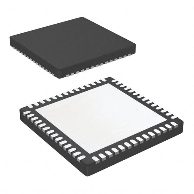
Texas Instruments TLC5958RTQT
- Part No.:
- TLC5958RTQT
- Manufacturer:
- Texas Instruments
- Category:
- LED Drivers
- Package:
- 56-VFQFN Exposed Pad
- Datasheet:
-
 TLC5958RTQT.pdf
- Description:
- IC LED DRIVER LINEAR 25MA 56QFN
- Quantity:
- Payment:

- Shipping:

Inventory:189
Please send an inquiry. Send us your inquiry, and we will respond immediately.
Product details
Overview
TLC5958RTQT from Texas Instruments is a 48-channel, 16-bit enhanced-spectrum PWM LED driver with integrated 48K-bit display memory, pre-charge FET, and LED open detection (LOD). It delivers constant-current sink outputs up to 25 mA per channel at 5 VCC, supports 32-multiplexing, and operates across –40°C to +85°C for high-density video displays and signage.
For engineers reviewing the TLC5958RTQT datasheet, TLC5958RTQT pinout, TLC5958RTQT application, or TLC5958RTQT equivalent, key selection criteria include its 16-bit grayscale resolution, 3-bit global + 9-bit per-color brightness control, thermal shutdown (170°C), IREF resistor short protection, and daisy-chainable serial interface with 25 MHz SCLK and 33 MHz GCLK.
Technical Context
The TLC5958RTQT implements an ES-PWM architecture with dual 48K-bit SRAM banks (A/B) enabling seamless frame buffering for flicker-free 32-line multiplexed LED scanning. Its 48 output channels are grouped into three 16-channel color banks (R/G/B), each independently adjustable via 9-bit color brightness control (CC) and collectively scaled by 3-bit global brightness control (BC).
It features a dedicated grayscale clock (GCLK) input that drives internal 16-bit counters for precise PWM timing, LAT-controlled data latching, and SIN/SCLK/SOUT serial interface supporting daisy-chaining. Built-in LOD flag reporting, thermal shutdown (TSD), and power-save mode (0.8 mA typ) support robust operation in high-reliability LED systems.
Key Specifications
| Parameter | Value and Actual Design Meaning |
|---|---|
| Channels | 48 constant-current sink outputs (16 red, 16 green, 16 blue) |
| Grayscale resolution | 16-bit (65,536 steps) per channel, implemented via ES-PWM for improved low-gray uniformity |
| Max sink current | 25 mA per channel at VCC = 4–5.5 V; 20 mA at 3.0–3.6 V |
| Current accuracy | ±3% max channel-to-channel; ±2% max device-to-device at 25 mA |
| Memory & multiplexing | 48K-bit display memory supporting up to 32-line multiplexing with dual-bank frame buffering |
| Serial interface | 25 MHz max SCLK; 33 MHz max GCLK; daisy-chainable via SIN/SOUT |
| Protection features | LED open detection (LOD), thermal shutdown (170°C), IREF short protection, power-save mode (0.8 mA) |
Pinout & Package
VQFN-56 package (8.0 mm × 8.0 mm) with exposed thermal pad soldered to PCB ground for thermal management.
| Pin/Terminal | Circuit Role | Design Meaning |
|---|---|---|
| GCLK (Pin 29) | Grayscale clock input | Rising edge increments internal 16-bit GS counter; defines PWM period and visual refresh timing |
| LAT (Pin 27) | Data latch control | Falling edge transfers shift register contents to GS memory or FC registers; synchronizes frame updates |
| SCLK (Pin 28) | Serial clock input | Rising edge shifts data into 48-bit common shift register; enables daisy-chain configuration |
| SIN (Pin 26) | Serial data input | LSB-first data stream for GS, BC, CC, or FC register writes; supports command encoding |
| SOUT (Pin 42) | Serial data output | MSB of shift register; enables cascading multiple TLC5958RTQT devices without external logic |
| IREF (Pin 1) | Current reference input | Connects external resistor to set max channel current; VIREF = 1.209 V (typ); gain varies with BC code |
| IREFGND (Pin 56) | Analog ground reference | Dedicated AGND for IREF resistor; must be routed separately to minimize noise coupling |
| OUTR0–OUTR15 (Pins 2,5,8,11,14,17,20,23,30,33,36,39,44,47,50,53) | Red LED constant-current sinks | Individually PWM-controlled; support voltage up to 10 V; can be paralleled for higher current |
| OUTG0–OUTG15 (Pins 3,6,9,12,15,18,21,24,31,34,37,40,45,48,51,54) | Green LED constant-current sinks | Same electrical specs as red group; independent CC register allows white-point tuning |
| OUTB0–OUTB15 (Pins 4,7,10,13,16,19,22,25,32,35,38,41,46,49,52,55) | Blue LED constant-current sinks | Same electrical specs; full 16-bit GS control per channel enables fine color gradation |
| VCC (Pin 43) | Power supply | 3.0–5.5 V digital/analog supply; powers logic, memory, and analog current sources |
| GND / Thermal Pad | Ground reference & thermal path | Thermal pad (bottom center) must be soldered to PCB ground plane for thermal dissipation (RθJB = 5.5°C/W) |
Key Features
| Feature | Design Value |
|---|---|
| 48K-bit dual-bank display memory | Enables real-time frame buffering for flicker-free 32-line multiplexing without host CPU intervention |
| Pre-charge FET with delay switching | Eliminates ghosting in high-speed multiplexed panels by synchronizing LED turn-on with line enable |
| LED open detection (LOD) | Single error flag reports open-circuit condition per channel; readable via serial interface for diagnostics |
| Enhanced Spectrum (ES) PWM | 16-bit grayscale with optimized bit weighting improves visual uniformity at low brightness levels |
| Programmable group delay | Adjusts timing offset between R/G/B groups to compensate for LED forward-voltage mismatches |
| Power-save mode | Reduces total supply current to 0.8 mA (typ) when all outputs are off-critical for standby efficiency |
Applications
| LED Video Wall Controller | High-Density Outdoor Signage |
|---|---|
|
Use Scenario: Driving 16×16 RGB pixel modules in large-format indoor video walls with >3,000 Hz refresh rate. IC Role / Device Role / Timing Role: Primary grayscale PWM controller managing 48 parallel LED strings per tile; handles frame buffering and multiplex timing via dual SRAM banks. Use Value: 16-bit ES-PWM ensures smooth dimming down to 0.001% brightness; LOD flag enables automated dead-pixel detection during calibration. |
Use Scenario: Controlling 32-line multiplexed RGB LED signs in sunlight-visible outdoor applications requiring wide temperature range operation. IC Role / Device Role / Timing Role: Constant-current sink driver with thermal shutdown (170°C) and 10 V LED supply tolerance for high-Vf blue/white LEDs. Use Value: Pre-charge FET eliminates ghosting under rapid scan; BC/CC registers allow dynamic daylight/nighttime brightness scaling without firmware update. |
| Stage Lighting Fixture | Medical Imaging Display Backlight |
|
Use Scenario: Precision dimming of RGBW LED arrays in programmable stage lighting fixtures requiring flicker-free output at 100+ Hz. IC Role / Device Role / Timing Role: High-accuracy current sink (±2% device-to-device) with independent color group control for calibrated white-point stability. Use Value: 9-bit per-color CC + 3-bit BC enables 512 × 8-step fine-tuning; 25 mA max drive supports high-lumen LEDs without external boosters. |
Use Scenario: Backlight driving for diagnostic-grade medical LCDs where grayscale fidelity and zero flicker are mandatory. IC Role / Device Role / Timing Role: Grayscale engine with 48K-bit memory ensuring consistent 16-bit luminance mapping across 32 vertical zones. Use Value: ES-PWM reduces low-gray banding; power-save mode enables instant on/off response; LOD prevents undetected backlight failure in safety-critical systems. |
Equivalent & Alternatives
The following parts are listed as comparable options for similar LED driver applications.
| Alternative Part | Technical Difference | Application Difference | Selection Advice |
|---|---|---|---|
| TLC5947RTQT | 16-channel, 12-bit PWM, no display memory, no LOD, lower max current (120 mA total) | Targeted at smaller panels (< 8×8) with simpler control; lacks multiplex support and frame buffering | Select when cost-sensitive, low-channel-count designs prioritize simplicity over advanced diagnostics and memory |
| IS31FL3733-QFLS4 | 48-channel, 16-bit PWM, integrated 32-line memory, but no pre-charge FET or LOD reporting | Supports multiplexing but requires external circuitry for ghosting suppression; no built-in open-detection flag | Choose when thermal performance and compact layout are critical, and LOD diagnostics are handled externally |
Compared with TLC5958RTQT, TLC5947RTQT offers lower integration and no multiplex capability, while IS31FL3733-QFLS4 provides comparable channel count and memory but omits key reliability features like LOD and pre-charge FET-making TLC5958RTQT optimal for mission-critical, high-refresh LED systems.
Availability
TLC5958RTQT is available at Aetrix Electronics and suitable for LED video walls, outdoor signage, stage lighting, and medical imaging displays requiring stable component supply, long-term lifecycle assurance, and traceable sourcing.
Supply support for TLC5958RTQT includes scheduled delivery planning, volume procurement assistance, BOM continuity management, traceable sourcing, and lifecycle availability coordination for OEM customers, industrial embedded developers, connected-device designers, and electronics production programs.
Manufacturer
Texas Instruments is a global semiconductor leader specializing in analog, embedded processing, and high-reliability ICs for industrial, automotive, and consumer applications.
The TLC5958RTQT belongs to TI's high-performance LED driver product line, engineered specifically for high-refresh, high-density multiplexed LED displays demanding precision grayscale, thermal resilience, and system-level diagnostics.
FAQ
What is the maximum LED supply voltage supported by the TLC5958RTQT?
The TLC5958RTQT supports LED anode voltages up to 10 V, enabling direct drive of high-forward-voltage blue and white LEDs without external boost circuitry. This rating is specified in the Absolute Maximum Ratings table (VOUT = –0.3 V to 11 V), and the device maintains constant-current regulation across this range when configured with appropriate IREF resistance and BC/CC settings. The TLC5958RTQT achieves this using robust output transistor design and thermal management via its exposed thermal pad.
How does the TLC5958RTQT implement LED open detection (LOD)?
The TLC5958RTQT integrates a per-channel LOD circuit that monitors output voltage during active sinking. When an open LED causes the output voltage to exceed a programmable threshold (VLOD0–VLOD3, selectable via FC2 register), the device sets a single LOD flag bit accessible through the serial interface. This flag reflects the logical OR of all 48 channels' open conditions-enabling fast system-level fault detection without polling each channel individually. The TLC5958RTQT does not report which specific channel is open, only that at least one is open.
Can the TLC5958RTQT be used in daisy-chain configurations, and what are the timing constraints?
Yes, the TLC5958RTQT supports seamless daisy-chaining via its SIN and SOUT pins. Data written to the first device's SIN propagates through SOUT to the next device's SIN on each SCLK rising edge. The maximum SCLK frequency remains 25 MHz regardless of chain length, but cumulative propagation delay requires careful PCB layout-especially for chains exceeding 5 devices. Latency between LAT pulse and effective GS update increases linearly with chain length, so frame synchronization must account for worst-case delay across all devices in the chain. The TLC5958RTQT's internal architecture ensures deterministic behavior under these conditions.
What is the role of the pre-charge FET in the TLC5958RTQT, and how does it prevent ghosting?
The pre-charge FET in the TLC5958RTQT briefly activates before the main current sink turns on during multiplexed scanning. This pre-charges the LED capacitance and parasitic wiring capacitance to near the LED forward voltage, eliminating the transient delay that causes faint "ghost" images on adjacent lines. The FET is synchronized to the line-enable timing and controlled internally-no external signals or configuration are required. This feature is especially critical in high-speed, high-density LED panels where ghosting would otherwise degrade image clarity. The TLC5958RTQT implements this function transparently as part of its multiplex timing engine.
How does the dual-bank 48K-bit memory improve display performance in the TLC5958RTQT?
The TLC5958RTQT's dual 48K-bit SRAM banks (A and B) enable concurrent display and update operations: while Bank A drives the current frame, Bank B accepts new grayscale data for the next frame via the serial interface. This eliminates visible tearing or stutter during rapid content changes and supports true 32-line multiplexing without host CPU bottlenecks. Each bank stores 16-bit data for all 48 channels across 32 lines (48 × 16 × 32 = 48K bits). The VSYNC command swaps active banks atomically-ensuring glitch-free transitions. This architecture is fundamental to the TLC5958RTQT's ability to sustain high visual refresh rates in professional LED displays.
TLC5958RTQT Specifications
- Product attributes
- Attribute value
- Manufacturer:
- Texas Instruments
- Series:
- -
- Package/Case:
- 56-VFQFN Exposed Pad
- Packaging:
- Tape & Reel (TR)
- Product Status:
- Active
- Type:
- Linear
- Topology:
- Shift Register
- Internal Switch(s):
- Yes
- Number of Outputs:
- 48
- Voltage - Supply (Min):
- 3V
- Voltage - Supply (Max):
- 5.5V
- Voltage - Output:
- 10V
- Current - Output / Channel:
- 25mA
- Frequency:
- -
- Dimming:
- -
- Applications:
- Signage
- Operating Temperature:
- -40°C ~ 85°C (TA)
- Grade:
- -
- Qualification:
- -
- Mounting Type:
- Surface Mount
- Supplier Device Package:
- 56-QFN (8x8)
TLC5958RTQT FAQ
1.How can I place an order for TLC5958RTQT through Aetrix?
Please submit a Request for Quotation (RFQ) for TLC5958RTQT on Aetrix. Our sales agent will provide a competitive quotation and guide you through the order confirmation once you accept the terms.
2.Are the price and stock information for TLC5958RTQT reliable?
The price and inventory of TLC5958RTQT are updated periodically and may fluctuate due to market conditions. Stock and pricing data are typically refreshed every 24 hours. Quotation validity for TLC5958RTQT is usually 5 days.
3.What payment methods are accepted for TLC5958RTQT?
We accept Wire Transfer, PayPal, Credit Card, Western Union, MoneyGram, and Escrow for TLC5958RTQT transactions.
Note: Certain payment methods may incur a processing fee.
4.How is shipping managed for TLC5958RTQT?
TLC5958RTQT orders can be shipped via leading logistics carriers, including DHL, UPS, FedEx, TNT, or Registered Mail.
Once your TLC5958RTQT order is processed, you will receive an email with the shipment details and tracking number.
Note: Tracking information may take up to 24 hours to appear. Express delivery typically takes 3–5 business days.
5.How can I obtain technical support or documentation for TLC5958RTQT?
For technical support, including TLC5958RTQT datasheets, pinout diagrams, or application guidance, please contact our engineering support team. They can provide detailed documentation and assistance for your TLC5958RTQT requirements.
6.How does Aetrix verify that TLC5958RTQT is sourced from the original manufacturer or authorized distributors?
All TLC5958RTQT products on Aetrix are procured from qualified distributors and authorized channels. Our dedicated quality assurance team conducts strict verification, including traceability checks and, if necessary, third-party testing. This ensures that TLC5958RTQT meets industry standards.
7.What is the process for return or replacement of TLC5958RTQT?
All TLC5958RTQT units undergo pre-shipment inspection (PSI). If there is an issue with TLC5958RTQT, returns or replacements are accepted under the following conditions:
1.Quantity discrepancies, incorrect items, or visible external defects (such as breakage or corrosion), acknowledged by Aetrix.
2.The issue is reported within 90 days of delivery.
3.The TLC5958RTQT part is unused and in its original packaging.
Return procedure for TLC5958RTQT:
1.Submit a request within 90 days.
2.Obtain a Return Material Authorization (RMA) from Aetrix.
TLC5958RTQT Tags

-
BCR402RE6327HTSA1
Infineon Technologies

-
BCR430UXTSA2
Infineon Technologies

-
BCR420UE6433HTMA1
Infineon Technologies
-
BCR420UE6327HTSA1
Infineon Technologies
-
BCR421UE6327HTSA1
Infineon Technologies

-
LYT1604D-TL
Power Integrations

-
HV9910CLG-G
Microchip Technology

-
CL2N8-G
Microchip Technology

-
BCR420UW6-7
Diodes Incorporated
-
BCR421UW6-7
Diodes Incorporated

-
BCR420UFD-7
Diodes Incorporated
-
BCR421UFD-7
Diodes Incorporated
Tech Hub

A practical engineering guide to 3.3V and 5V logic compatibility, input thresholds, resistor dividers, translator ICs, MOSFET level shifting, I2C pull-ups, timing limits and power-sequencing risks.

The 74HC595 uses push-pull logic outputs, while the TPIC6B595 uses 50 V open-drain DMOS sinks for higher-power loads. This guide compares timing, current limits, 3.3 V interfacing, load wiring, thermal…

The 74HC595 converts serial data into eight stable parallel outputs. This guide covers pin functions, shift and storage timing, OE and MR behavior, drive-current limits, cascading, voltage compatibilit…

A technical comparison of level-sensitive latches and edge-triggered flip-flops, covering timing windows, setup and hold limits, master–slave operation, time borrowing, race-through, HDL inference and…

A D latch stores one bit while Enable controls when data can pass. This reference covers gate-level operation, truth tables, transparency, setup and hold timing, LE versus OE, common ICs and practical …

An SR latch stores one bit through cross-coupled feedback. This engineering reference covers NOR and NAND implementations, truth tables, forbidden-state recovery, gated operation, switch debouncing, fa…

Latch circuits retain one bit through feedback. This technical reference covers SR and D latches, truth tables, transparency, timing limits, latch-versus-flip-flop behavior, applications and common log…

An engineering guide to LED driver operation, constant-current and constant-voltage outputs, linear and switching topologies, dimming, IC selection, calculations, replacement compatibility, and fault c…

Operational amplifier guide covering op amp basics, feedback, ideal vs real op amps, common configurations, buffer circuits, offset, bias current, gain-bandwidth, slew rate, rail-to-rail limits and sel…

Jumper cables guide covering safe connection order, red and black clamp placement, final ground connection, cable gauge, length, clamp quality, copper vs CCA cables, jump starter comparison and battery…


