
 My Inquiry
 My Account


Texas Instruments TLC5971PWP
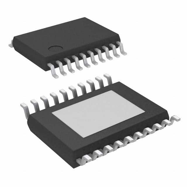
- Part No.:
- TLC5971PWP
- Manufacturer:
- Texas Instruments
- Category:
- LED Drivers
- Package:
- 20-PowerTSSOP (0.173", 4.40mm Width)
- Datasheet:
-
 TLC5971PWP.pdf
- Description:
- IC LED DRVR LINEAR 60MA 20HTSSOP
- Quantity:
- Payment:

- Shipping:

Inventory:1,280
Please send an inquiry. Send us your inquiry, and we will respond immediately.
Product details
Overview
TLC5971PWP from Texas Instruments is a 12-channel, 16-bit PWM RGB LED driver with integrated 3.3-V linear regulator, constant-current sink outputs (60 mA per channel), enhanced spectrum grayscale control (65536 steps), and global brightness control (128 steps per color group). It operates from 6 V to 17 V via internal regulator or 3 V to 5.5 V directly, supporting high-fidelity color-mixed LED cluster displays in signage and architectural lighting.
For engineers reviewing the TLC5971PWP datasheet, TLC5971PWP pinout, TLC5971PWP application, or TLC5971PWP equivalent, key selection considerations include its 20-pin HTSSOP package with PowerPAD, cascading capability for unlimited device chaining, thermal shutdown with auto-restart, and dual power supply modes enabling flexible system-level integration in space-constrained RGB LED systems.
Technical Context
The TLC5971PWP implements a 224-bit shift register with serial two-wire interface (SDTI/SCKI) and daisy-chain output (SDTO/SCKO), supporting up to 20 MHz clock rate. Its PWM engine delivers 16-bit grayscale resolution per channel with independent per-group global brightness scaling using 7-bit BC registers.
Each of the 12 outputs (OUTR0–OUTR3, OUTG0–OUTG3, OUTB0–OUTB3) is a constant-current sink with ±1% channel-to-channel and device-to-device accuracy, programmable via external IREF resistor. Internal thermal shutdown activates at 150°C junction temperature with 10°C hysteresis, and the integrated 3.3-V linear regulator supplies up to –25 mA while accepting 6–17 V input.
Key Specifications
| Parameter | Value and Actual Design Meaning |
|---|---|
| Output channels | 12 constant-current sinks (4 red, 4 green, 4 blue) - enables full RGB pixel control per channel group |
| Grayscale resolution | 16-bit (65536 steps) per channel - supports smooth, flicker-free dimming without visible banding |
| Global brightness control | 7-bit (128 steps) per color group - allows fine-tuned white-point adjustment and ambient light compensation |
| Max output current | 60 mA per channel (typical) - sufficient to drive standard 20-mA RGB LEDs at overdrive for high-brightness applications |
| Supply voltage range | 6 V to 17 V (internal regulator mode) or 3 V to 5.5 V (direct mode) - accommodates wide-input industrial and automotive LED power rails |
| Constant-current accuracy | ±1% channel-to-channel (typical) - ensures uniform luminance across multi-LED arrays without per-channel calibration |
| Data clock frequency | Up to 20 MHz - enables fast frame updates for dynamic video content on LED walls |
Pinout & Package
The TLC5971PWP uses a 20-pin HTSSOP package (6.50 mm × 4.40 mm) with exposed PowerPAD thermal pad on the bottom side for enhanced heat dissipation in high-current operation.
| Pin/Terminal | Circuit Role | Design Meaning |
|---|---|---|
| GND (Pin 2) | Power ground reference | Primary return path for all internal circuits and output current sinks; must be low-impedance connection to PCB ground plane |
| VREG (Pin 20) | 3.3-V linear regulator output | Provides regulated 3.3-V supply for external logic or other TLC5971 devices; requires 1-µF decoupling capacitor |
| IREF (Pin 1) | Current reference programming node | External resistor to GND sets maximum sink current for all 12 channels; open or short disables outputs |
| SDTI (Pin 9) | Serial data input | Accepts 224-bit command/data stream synchronized to SCKI rising edge; LSB-first protocol |
| SCKI (Pin 10) | Serial clock input | Drives internal shift register and latches; rising edge clocks data into SDTI and advances SDTO output |
| VCC (Pin 19) | Main power supply input | Accepts 6–17 V for internal regulator operation or 3–5.5 V for direct supply; powers all internal circuitry and outputs |
| OUTR0–OUTR3 (Pins 3,6,13,16) | Red LED constant-current sinks | Four dedicated red-channel outputs; each independently controlled via grayscale and BC registers |
| OUTG0–OUTG3 (Pins 4,7,14,17) | Green LED constant-current sinks | Four dedicated green-channel outputs; grouped for simultaneous global brightness scaling |
| OUTB0–OUTB3 (Pins 5,8,15,18) | Blue LED constant-current sinks | Four dedicated blue-channel outputs; supports RGB color mixing with matched current accuracy |
| SDTO (Pin 12) | Serial data output | MSB of internal shift register; enables daisy-chaining multiple TLC5971 devices without external logic |
| SCKO (Pin 11) | Serial clock output | Re-timed SCKI signal synchronized to SDTO propagation delay; ensures reliable inter-device timing |
Key Features
| Feature | Design Value |
|---|---|
| Enhanced spectrum PWM | 16-bit grayscale with optimized bit weighting reduces visual artifacts and improves color fidelity in static and animated content |
| Auto display repeat function | Enables continuous playback of stored GS/BC data without host MCU intervention - reduces firmware overhead in embedded controllers |
| Display timing reset function | Hardware-synchronized latch pulse generation ensures precise frame alignment across cascaded devices in large LED arrays |
| Unlimited device cascading | SDTO/SCKO interface supports arbitrary-length chains - simplifies expansion of RGB pixel count without address management complexity |
| Thermal shutdown with auto restart | Protects against overtemperature failure during sustained high-current operation; resumes normal function after cooling below hysteresis threshold |
Applications
| Architectural LED Facades | Stage Lighting Systems |
|---|---|
Use Scenario: Large-scale building exteriors with thousands of individually addressable RGB pixels driven by centralized controllers. IC Role / Device Role / Timing Role: Constant-current sink driver providing precise per-pixel color and brightness control via cascaded daisy-chain topology. Use Value: ±1% channel-to-channel current matching ensures uniform luminance across façade panels; 20-MHz data clock supports real-time video rendering at 60 fps. | Use Scenario: Programmable moving-head and wash fixtures requiring smooth color transitions and high dynamic range. IC Role / Device Role / Timing Role: RGB channel controller implementing 16-bit PWM dimming and per-group global brightness scaling for white-point tuning. Use Value: Enhanced spectrum PWM eliminates contouring in gradients; auto-display repeat reduces host processor load during static scenes. |
| RGB Video Wall Controllers | Automotive Interior Mood Lighting |
Use Scenario: Modular LED video walls where tiles contain local drivers and communicate via high-speed serial interface. IC Role / Device Role / Timing Role: Local pixel driver receiving serialized GS/BC data over SDTI/SCKI and driving 12 discrete LED strings per tile. Use Value: SDTO/SCKO daisy-chain capability enables seamless tile-to-tile synchronization; thermal shutdown protects against enclosure overheating. | Use Scenario: Ambient cabin lighting with tunable white and RGB zones controlled via vehicle infotainment system. IC Role / Device Role / Timing Role: Low-voltage LED driver operating from 12-V automotive supply via internal 3.3-V regulator for microcontroller interfacing. Use Value: 6–17 V input range tolerates battery transients; ±1% device-to-device accuracy maintains consistent color across multiple modules. |
Equivalent & Alternatives
The following parts are listed as comparable options for similar RGB LED driver applications.
| Alternative Part | Technical Difference | Application Difference | Selection Advice |
|---|---|---|---|
| TLC5971RGE | 24-pin VQFN package (4.00 mm × 4.00 mm); identical electrical specs and feature set | Better thermal performance (θJA = 38°C/W vs 68.6°C/W) and smaller footprint - preferred for high-density PCB layouts | Select TLC5971RGE when board space or thermal management is critical; same register map and software compatibility |
| IS31FL3731 | 18-channel, 8-bit PWM driver with I²C interface; no integrated linear regulator; max 40 mA/channel | Supports matrix scanning and built-in breathing effects; requires external 3.3-V supply and level-shifting for 5-V systems | Choose IS31FL3731 for cost-sensitive, lower-resolution applications needing I²C simplicity and animation features |
Compared with TLC5971RGE, the TLC5971PWP offers identical functionality in a larger HTSSOP package better suited for manual assembly and thermal testing; versus IS31FL3731, it provides higher resolution, higher current, and integrated power regulation at the cost of SPI-only interface and larger die size.
Availability
TLC5971PWP is available at Aetrix Electronics and suitable for RGB LED cluster lamp displays, architectural façade lighting, and stage lighting systems requiring stable component supply, long-term production continuity, and guaranteed TI original sourcing.
Supply support for TLC5971PWP includes scheduled delivery planning, volume procurement assistance, BOM continuity management, traceable sourcing, and lifecycle availability coordination for OEM customers, industrial embedded developers, connected-device designers, and electronics production programs.
Manufacturer
Texas Instruments is a global semiconductor company specializing in analog and embedded processing technologies, with leadership in power management, signal chain, and high-reliability ICs.
The TLC5971 product line was designed specifically for high-fidelity, multi-color LED illumination systems requiring precise current matching, high PWM resolution, and robust thermal protection in commercial and industrial environments.
FAQ
What is the maximum number of TLC5971PWP devices that can be cascaded?
The TLC5971PWP supports unlimited device cascading via its SDTO and SCKO pins, enabling arbitrarily long daisy chains without external logic. Each device forwards the shifted data and re-timed clock to the next, preserving timing integrity across hundreds of units in large-scale LED installations. This architecture eliminates address configuration overhead and simplifies firmware for systems like video walls or façade controllers.
Does the TLC5971PWP require an external crystal or oscillator?
No, the TLC5971PWP contains an internal oscillator (6–12 MHz typical) that generates the grayscale clock; no external crystal or oscillator is needed. The device supports both internal and selectable external GS clock sources via the EXTGCK bit in the data latch, allowing synchronization to a master system clock when precise inter-device timing alignment is required.
How does the IREF pin set output current on the TLC5971PWP?
The IREF pin on the TLC5971PWP accepts an external resistor to GND; the resulting current sets the full-scale sink current for all 12 output channels. With a 0.82-kΩ resistor, the typical output is 60 mA per channel. The relationship is inverse-linear: lower resistance increases current, and direct short to GND forces all outputs off. Placement near the pin minimizes noise coupling.
Can the TLC5971PWP drive LEDs with forward voltages exceeding 17 V?
No, the TLC5971PWP specifies a maximum output voltage (VO) of 17 V across all OUTXn pins. Attempting to drive LED strings with combined forward voltage above this limit risks violating absolute maximum ratings and may cause premature device failure. For higher-voltage strings, external high-side switching or alternative drivers with higher compliance voltage must be used.
What thermal management is required for continuous 60-mA operation on all 12 channels of the TLC5971PWP?
At full 60-mA load per channel (720 mA total sink current), the TLC5971PWP dissipates ~1.5 W in typical conditions. The 20-pin HTSSOP package has θJA = 68.6°C/W; with 2-oz copper PowerPAD soldering, junction temperature rise is ~103°C above ambient. To maintain TJ ≤ 125°C, ambient must stay below +22°C - thus forced air or heatsinking is required for sustained full-load operation in enclosed environments.
TLC5971PWP Specifications
- Product attributes
- Attribute value
- Manufacturer:
- Texas Instruments
- Series:
- -
- Package/Case:
- 20-PowerTSSOP (0.173", 4.40mm Width)
- Packaging:
- Tube
- Product Status:
- Active
- Type:
- Linear
- Topology:
- Shift Register
- Internal Switch(s):
- Yes
- Number of Outputs:
- 12
- Voltage - Supply (Min):
- 3V
- Voltage - Supply (Max):
- 5.5V
- Voltage - Output:
- 17V
- Current - Output / Channel:
- 60mA
- Frequency:
- -
- Dimming:
- -
- Applications:
- -
- Operating Temperature:
- -40°C ~ 85°C (TA)
- Grade:
- -
- Qualification:
- -
- Mounting Type:
- Surface Mount
- Supplier Device Package:
- 20-HTSSOP
TLC5971PWP FAQ
1.How can I place an order for TLC5971PWP through Aetrix?
Please submit a Request for Quotation (RFQ) for TLC5971PWP on Aetrix. Our sales agent will provide a competitive quotation and guide you through the order confirmation once you accept the terms.
2.Are the price and stock information for TLC5971PWP reliable?
The price and inventory of TLC5971PWP are updated periodically and may fluctuate due to market conditions. Stock and pricing data are typically refreshed every 24 hours. Quotation validity for TLC5971PWP is usually 5 days.
3.What payment methods are accepted for TLC5971PWP?
We accept Wire Transfer, PayPal, Credit Card, Western Union, MoneyGram, and Escrow for TLC5971PWP transactions.
Note: Certain payment methods may incur a processing fee.
4.How is shipping managed for TLC5971PWP?
TLC5971PWP orders can be shipped via leading logistics carriers, including DHL, UPS, FedEx, TNT, or Registered Mail.
Once your TLC5971PWP order is processed, you will receive an email with the shipment details and tracking number.
Note: Tracking information may take up to 24 hours to appear. Express delivery typically takes 3–5 business days.
5.How can I obtain technical support or documentation for TLC5971PWP?
For technical support, including TLC5971PWP datasheets, pinout diagrams, or application guidance, please contact our engineering support team. They can provide detailed documentation and assistance for your TLC5971PWP requirements.
6.How does Aetrix verify that TLC5971PWP is sourced from the original manufacturer or authorized distributors?
All TLC5971PWP products on Aetrix are procured from qualified distributors and authorized channels. Our dedicated quality assurance team conducts strict verification, including traceability checks and, if necessary, third-party testing. This ensures that TLC5971PWP meets industry standards.
7.What is the process for return or replacement of TLC5971PWP?
All TLC5971PWP units undergo pre-shipment inspection (PSI). If there is an issue with TLC5971PWP, returns or replacements are accepted under the following conditions:
1.Quantity discrepancies, incorrect items, or visible external defects (such as breakage or corrosion), acknowledged by Aetrix.
2.The issue is reported within 90 days of delivery.
3.The TLC5971PWP part is unused and in its original packaging.
Return procedure for TLC5971PWP:
1.Submit a request within 90 days.
2.Obtain a Return Material Authorization (RMA) from Aetrix.
TLC5971PWP Tags

-
BCR402RE6327HTSA1
Infineon Technologies

-
BCR430UXTSA2
Infineon Technologies

-
BCR420UE6433HTMA1
Infineon Technologies
-
BCR420UE6327HTSA1
Infineon Technologies
-
BCR421UE6327HTSA1
Infineon Technologies

-
LYT1604D-TL
Power Integrations

-
HV9910CLG-G
Microchip Technology

-
CL2N8-G
Microchip Technology

-
BCR420UW6-7
Diodes Incorporated
-
BCR421UW6-7
Diodes Incorporated

-
BCR420UFD-7
Diodes Incorporated
-
BCR421UFD-7
Diodes Incorporated
Tech Hub

A practical engineering guide to 3.3V and 5V logic compatibility, input thresholds, resistor dividers, translator ICs, MOSFET level shifting, I2C pull-ups, timing limits and power-sequencing risks.

The 74HC595 uses push-pull logic outputs, while the TPIC6B595 uses 50 V open-drain DMOS sinks for higher-power loads. This guide compares timing, current limits, 3.3 V interfacing, load wiring, thermal…

The 74HC595 converts serial data into eight stable parallel outputs. This guide covers pin functions, shift and storage timing, OE and MR behavior, drive-current limits, cascading, voltage compatibilit…

A technical comparison of level-sensitive latches and edge-triggered flip-flops, covering timing windows, setup and hold limits, master–slave operation, time borrowing, race-through, HDL inference and…

A D latch stores one bit while Enable controls when data can pass. This reference covers gate-level operation, truth tables, transparency, setup and hold timing, LE versus OE, common ICs and practical …

An SR latch stores one bit through cross-coupled feedback. This engineering reference covers NOR and NAND implementations, truth tables, forbidden-state recovery, gated operation, switch debouncing, fa…

Latch circuits retain one bit through feedback. This technical reference covers SR and D latches, truth tables, transparency, timing limits, latch-versus-flip-flop behavior, applications and common log…

An engineering guide to LED driver operation, constant-current and constant-voltage outputs, linear and switching topologies, dimming, IC selection, calculations, replacement compatibility, and fault c…

Operational amplifier guide covering op amp basics, feedback, ideal vs real op amps, common configurations, buffer circuits, offset, bias current, gain-bandwidth, slew rate, rail-to-rail limits and sel…

Jumper cables guide covering safe connection order, red and black clamp placement, final ground connection, cable gauge, length, clamp quality, copper vs CCA cables, jump starter comparison and battery…


